2001 DODGE TOWN AND COUNTRY horn
[x] Cancel search: hornPage 1 of 2321

GROUP TAB LOCATOR
INIntroduction
INaIntroduction
0Lubrication & Maintenance
0aLubrication & Maintenance
2Suspension
2aSuspension
3Differential & Driveline
5Brakes
5aBrakes
6aClutch
7Cooling
7aCooling
8AAudio
8AaAudio
8BChime/Buzzer
8BaChime/Buzzer
8EElectronic Control Modules
8FEngine Systems
8FaEngine Systems
8GHeated Systems
8HHorn
8IIgnition Control
8JInstrument Cluster
8JaInstrument Cluster
8LLamps
8LaLamps
8MMessage Systems
8NPower Systems
8NaPower Systems
8ORestraints
8PSpeed Control
8QVehicle Theft Security
8RWipers/Washers
8WaWiring
9Engine
9aEngine
11Exhaust System
11aExhaust System
13Frame & Bumpers
14Fuel System
14aFuel System
19Steering
19aSteering
21Transmission/Transaxle
21aTransmission/Transaxle
22Tires/Wheels
23Body
24Heating & Air Conditioning
24aHeating & Air Conditioning
25Emissions Control
25aEmissions Control
Service Manual Comment Forms
ProCarManuals.com
Page 6 of 2321
FASTENER IDENTIFICATION
DESCRIPTION
The SAE bolt strength grades range from grade 2
to grade 8. The higher the grade number, the greater
the bolt strength. Identification is determined by the
line marks on the top of each bolt head. The actual
bolt strength grade corresponds to the number of line
marks plus 2. The most commonly used metric bolt
strength classes are 9.8 and 10.9. The metric
strength class identification number is imprinted on
the head of the bolt. The higher the class number,
the greater the bolt strength. Some metric nuts are
imprinted with a single-digit strength class on the
nut face. Refer to the Fastener Identification and
Fastener Strength Charts.
FASTENER USAGE
DESCRIPTION - FASTENER USAGE
WARNING: USE OF AN INCORRECT FASTENER
MAY RESULT IN COMPONENT DAMAGE OR PER-
SONAL INJURY.
Figure art, specifications and torque references in
this Service Manual are identified in metric and SAE
format.
During any maintenance or repair procedures, it is
important to salvage all fasteners (nuts, bolts, etc.)
for reassembly. If the fastener is not salvageable, a
fastener of equivalent specification must be used.
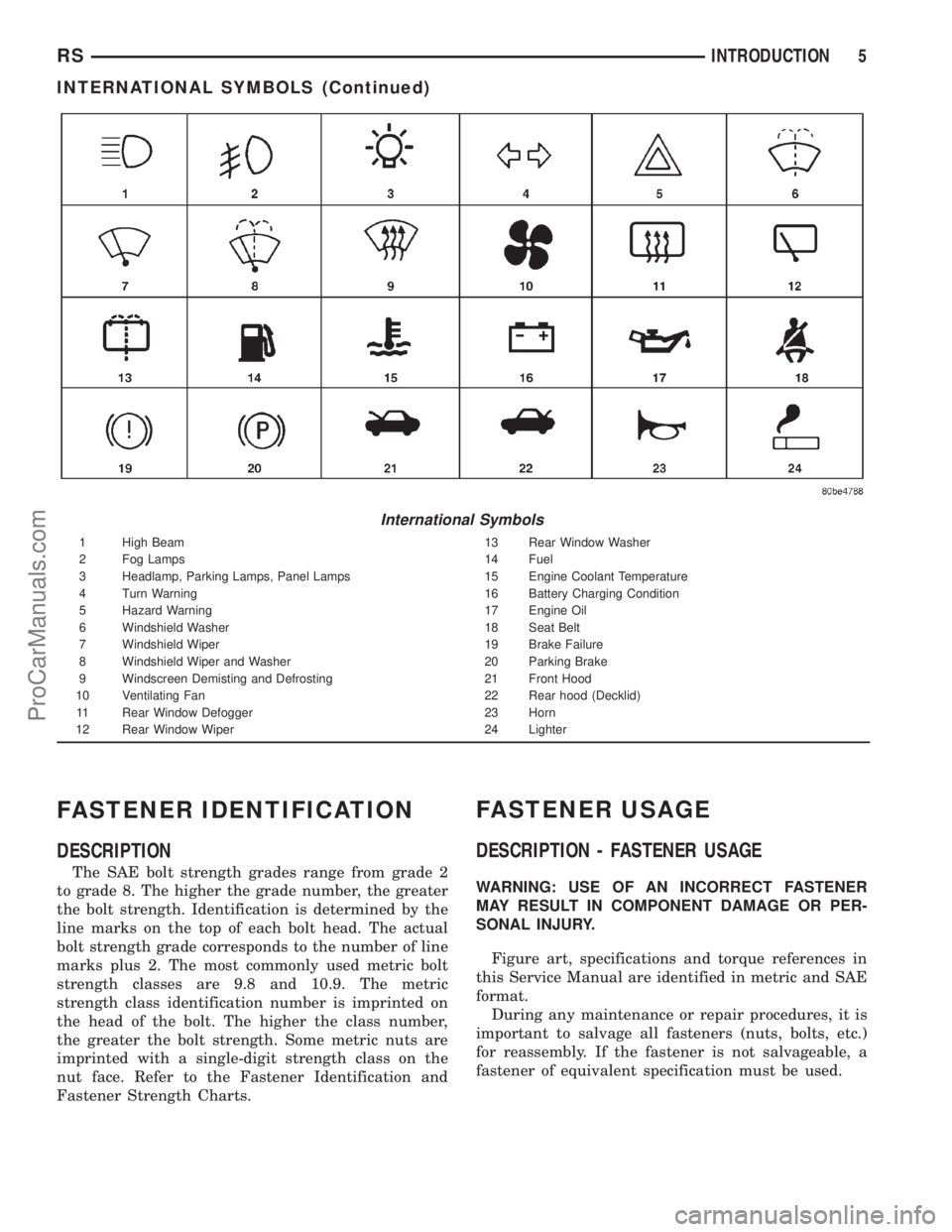
International Symbols
1 High Beam 13 Rear Window Washer
2 Fog Lamps 14 Fuel
3 Headlamp, Parking Lamps, Panel Lamps 15 Engine Coolant Temperature
4 Turn Warning 16 Battery Charging Condition
5 Hazard Warning 17 Engine Oil
6 Windshield Washer 18 Seat Belt
7 Windshield Wiper 19 Brake Failure
8 Windshield Wiper and Washer 20 Parking Brake
9 Windscreen Demisting and Defrosting 21 Front Hood
10 Ventilating Fan 22 Rear hood (Decklid)
11 Rear Window Defogger 23 Horn
12 Rear Window Wiper 24 Lighter
RSINTRODUCTION5
INTERNATIONAL SYMBOLS (Continued)
ProCarManuals.com
Page 16 of 2321
FASTENER USAGE
DESCRIPTION
WARNING: USE OF AN INCORRECT FASTENER
MAY RESULT IN COMPONENT DAMAGE OR PER-
SONAL INJURY.
Figure art, specifications and torque references in
this Service Manual are identified in metric and SAE
format.
During any maintenance or repair procedures, it is
important to salvage all fasteners (nuts, bolts, etc.)
for reassembly. If the fastener is not salvageable, a
fastener of equivalent specification must be used.
THREADED HOLE REPAIR
DESCRIPTION
Most stripped threaded holes can be repaired using
a Helicoilt. Follow the vehicle or Helicoiltrecommen-
dations for application and repair procedures.
INTERNATIONAL VEHICLE
CONTROL & DISPLAY
SYMBOLS
DESCRIPTION
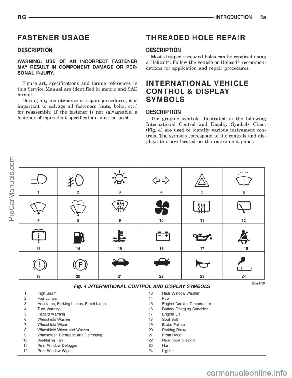
The graphic symbols illustrated in the following
International Control and Display Symbols Chart
(Fig. 4) are used to identify various instrument con-
trols. The symbols correspond to the controls and dis-
plays that are located on the instrument panel.
Fig. 4 INTERNATIONAL CONTROL AND DISPLAY SYMBOLS
1 High Beam 13 Rear Window Washer
2 Fog Lamps 14 Fuel
3 Headlamp, Parking Lamps, Panel Lamps 15 Engine Coolant Temperature
4 Turn Warning 16 Battery Charging Condition
5 Hazard Warning 17 Engine Oil
6 Windshield Washer 18 Seat Belt
7 Windshield Wiper 19 Brake Failure
8 Windshield Wiper and Washer 20 Parking Brake
9 Windscreen Demisting and Defrosting 21 Front Hood
10 Ventilating Fan 22 Rear hood (Decklid)
11 Rear Window Defogger 23 Horn
12 Rear Window Wiper 24 Lighter
RGINTRODUCTION5a
ProCarManuals.com
Page 363 of 2321
²Front Fog Lamp Relay Actuation
²Front and Rear Blower Motor Relay Actuation
²Accessory Relay Actuation
²Electronic Back Light (EBL) Rear Defogger
²Horn Relay Actuation
²Park Lamp Relay Actuation
²Name Brand Speaker (NBS) Relay Actuation
²Headlamp Washer Relay Actuation
²Diesel Cabin Heater (Diesel Engine Vehicles)
The following inputs areReceived/Monitoredby
the Front Control Module:
²B+ Connection Detection
²Ambient Temperature Sensing
²Right/Left Park Lamp Outage
²Ignition Switch Start Only
²Ignition Switch Run and Start Only
²Washer Fluid Level
²Windshield Wiper Park
²Brake Fluid Level
²Back-Up switch
²Stop Lamp Sense
²Engine Crank Signal (Diesel Engine Vehicles)
²Horn Input
DIAGNOSIS AND TESTING - FRONT CONTROL
MODULE
The front control module is a printed circuit board
based module with a on-board micro-processor. The
front control module interfaces with other electronic
modules in the vehicle via the Programmable Com-
munications Interface (PCI) data bus (J1850). In
order to obtain conclusive testing the Programmable
Communications Interface (PCI) data bus network
and all of the electronic modules that provide inputs
to, or receive outputs from the front control module
must be checked. All PCI (J1850) communication
faults must be resolved prior to further diagnosing
any front control module related issues.
The front control module was designed to be diag-
nosed with an appropriate diagnostic scan tool, such
as the DRB IIIt. The most reliable, efficient, and
accurate means to diagnose the front control module
requires the use of a DRB IIItscan tool and the
proper Body Diagnostic Procedures manual.
Before any testing of the front control module is
attempted, the battery should be fully charged and
all wire harness and ground connections inspected
around the affected areas on the vehicle.
REMOVAL
(1) Disconnect the positive and negative battery
cables from the battery.
(2) Remove the battery from the vehicle. Refer to
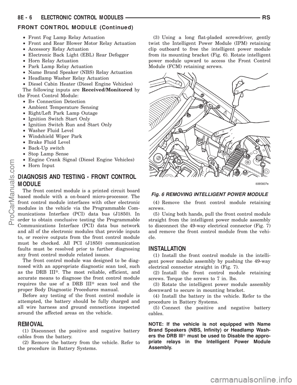
the procedure in Battery Systems.(3) Using a long flat-pladed screwdriver, gently
twist the Intelligent Power Module (IPM) retaining
clip outboard to free the intelligent power module
from its mounting bracket (Fig. 6). Rotate intelligent
power module upward to access the Front Control
Module (FCM) retaining screws.
(4) Remove the front control module retaining
screws.
(5) Using both hands, pull the front control module
straight from the intelligent power module assembly
to disconnect the 49-way electrical connector (Fig. 7)
and remove the front control module from the vehi-
cle.
INSTALLATION
(1) Install the front control module in the intelli-
gent power module assembly by pushing the 49-way
electrical connector straight in (Fig. 7).
(2) Install the front control module retaining
screws. Torque the screws to 7 in. lbs.
(3) Rotate the intelligent power module assembly
downward to secure in mounting bracket.
(4) Install the battery in the vehicle. Refer to the
procedure in Battery Systems.
(5) Connect the positive and negative battery
cables.
NOTE: If the vehicle is not equipped with Name
Brand Speakers (NBS, Infinity) or Headlamp Wash-
ers the DRB IIITmust be used to Disable the appro-
priate relays in the Intelligent Power Module
Assembly.
Fig. 6 REMOVING INTELLIGENT POWER MODULE
8E - 6 ELECTRONIC CONTROL MODULESRS
FRONT CONTROL MODULE (Continued)
ProCarManuals.com
Page 444 of 2321
HORN
TABLE OF CONTENTS
page page
HORN
DESCRIPTION............................1
OPERATION.............................1
DIAGNOSIS AND TESTING..................1
HORN
DIAGNOSIS AND TESTING..................3
REMOVAL...............................4INSTALLATION............................5
HORN RELAY
DIAGNOSIS AND TESTING..................5
REMOVAL...............................5
INSTALLATION............................5
HORN SWITCH
DESCRIPTION............................5
HORN
DESCRIPTION
HORN SYSTEM
WARNING:
ON VEHICLES EQUIPPED WITH AIRBAG, REFER TO
ELECTRICAL, RESTRAINTS FOR SAFETY PRECAU-
TIONS. DISCONNECT THE NEGATIVE CABLE FROM
THE BATTERY BEFORE SERVICING COMPONENTS
INVOLVING THE AIRBAG SYSTEM. ACCIDENTAL
DEPLOYMENT OF AIRBAG AND PERSONAL INJURY
CAN RESULT.
The horn circuit consists of a horn switch, clock-
spring, horn relay, horns and intelligent power mod-
ule. The horn switch is a membrane switch located in
the airbag trim cover. The horns are located forward
of the left front wheel behind the bumper fascia.
OPERATION
The horn relay plugs into the intelligent power
module which is located in the engine compartment.
For circuit information and component locations,
refer to the appropriate wiring information. The wir-
ing information includes wiring diagrams, proper
wire and connector repair procedures, details of wire
harness routing and retention, connector pin-out
information and location views for the various wire
harness connectors, splices and grounds.
The horns will not function if the switch is
ªCLOSEDº for more than 30 seconds. Once the
switch is ªOPENº, a 20±30 second delay will occur
before the horns are functional again.
DIAGNOSIS AND TESTING
Refer to Horn System Test below. If the horn does
not sound, check horn fuse located in the intelligent
power module. If the fuse is blown, replace with the
correct fuse. If the horns fail to sound and the new
fuse blows when depressing the horn switch, a short
circuit in the horn or the horn wiring between the
fuse terminal and the horn is responsible, or a defec-
tive horn switch allowed the horn to burn out is
responsible.
If the fuse is OK, test horn relay (Refer to 8 -
ELECTRICAL/HORN/HORN RELAY - DIAGNOSIS
AND TESTING).
If the relay is OK, test horn. Refer to Horn System
Test.
CAUTION:
Continuous sounding of horn may cause horn relay
to fail.
Should the horn sound continuously:
²Unplug the horn relay from intelligent power
module.
²Refer to (Refer to 8 - ELECTRICAL/HORN/
HORN RELAY - DIAGNOSIS AND TESTING).
Refer to the appropriate wiring information. The
wiring information includes wiring diagrams, proper
wire and connector repair procedures, details of wire
harness routing and retention, connector pin-out
information and location views for the various wire
harness connectors, splices and grounds.
RSHORN8H-1
ProCarManuals.com
Page 445 of 2321
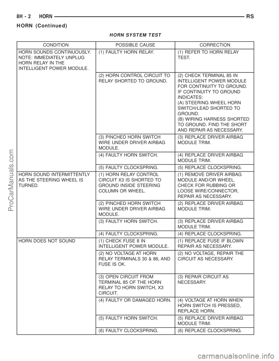
HORN SYSTEM TEST
CONDITION POSSIBLE CAUSE CORRECTION
HORN SOUNDS CONTINUOUSLY.
NOTE: IMMEDIATELY UNPLUG
HORN RELAY IN THE
INTELLIGENT POWER MODULE.(1) FAULTY HORN RELAY. (1) REFER TO HORN RELAY
TEST.
(2) HORN CONTROL CIRCUIT TO
RELAY SHORTED TO GROUND.(2) CHECK TERMINAL 85 IN
INTELLIGENT POWER MODULE
FOR CONTINUITY TO GROUND.
IF CONTINUITY TO GROUND
INDICATES:
(A) STEERING WHEEL HORN
SWITCH/LEAD SHORTED TO
GROUND.
(B) WIRING HARNESS SHORTED
TO GROUND. FIND THE SHORT
AND REPAIR AS NECESSARY.
(3) PINCHED HORN SWITCH
WIRE UNDER DRIVER AIRBAG
MODULE.(3) REPLACE DRIVER AIRBAG
MODULE TRIM.
(4) FAULTY HORN SWITCH. (4) REPLACE DRIVER AIRBAG
MODULE TRIM.
(5) FAULTY CLOCKSPRING. (5) REPLACE CLOCKSPRING.
HORN SOUND INTERMITTENTLY
AS THE STEERING WHEEL IS
TURNED.(1) HORN RELAY CONTROL
CIRCUIT X3 IS SHORTED TO
GROUND INSIDE STEERING
COLUMN OR WHEEL.(1) REMOVE DRIVER AIRBAG
MODULE AND/OR WHEEL.
CHECK FOR RUBBING OR
LOOSE WIRE/CONNECTOR,
REPAIR AS NECESSARY.
(2) PINCHED HORN SWITCH
WIRE UNDER DRIVER AIRBAG
MODULE.(2) REPLACE DRIVER AIRBAG
MODULE TRIM.
(3) FAULTY HORN SWITCH. (3) REPLACE DRIVER AIRBAG
MODULE TRIM.
(4) FAULTY CLOCKSPRING. (4) REPLACE CLOCKSPRING.
HORN DOES NOT SOUND (1) CHECK FUSE 8 IN
INTELLIGENT POWER MODULE.(1) REPLACE FUSE IF BLOWN
REPAIR AS NECESSARY.
(2) NO VOLTAGE AT HORN
RELAY TERMINALS 30 & 86, AND
FUSE IS OK.(2) NO VOLTAGE, REPAIR THE
CIRCUIT AS NECESSARY.
(3) OPEN CIRCUIT FROM
TERMINAL 85 OF THE HORN
RELAY TO HORN SWITCH, X3
CIRCUIT.(3) REPAIR CIRCUIT AS
NECESSARY.
(4) FAULTY OR DAMAGED HORN. (4) VOLTAGE AT HORN WHEN
HORN SWITCH IS PRESSED,
REPLACE HORN.
(5) FAULTY HORN SWITCH. (5) REPLACE DRIVER AIRBAG
MODULE TRIM.
(6) FAULTY CLOCKSPRING. (6) REPLACE CLOCKSPRING.
8H - 2 HORNRS
HORN (Continued)
ProCarManuals.com
Page 446 of 2321
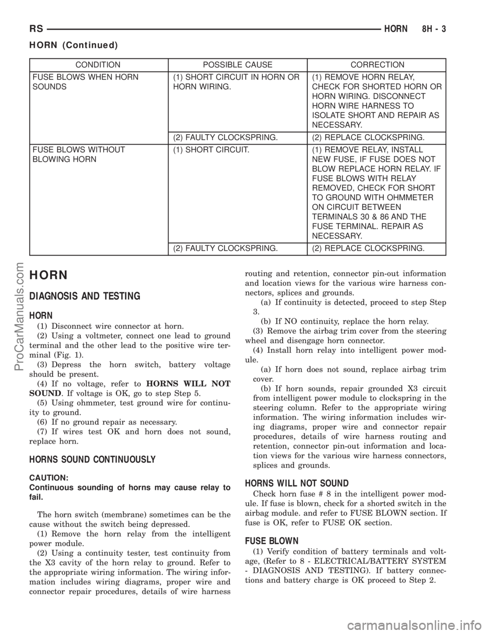
CONDITION POSSIBLE CAUSE CORRECTION
FUSE BLOWS WHEN HORN
SOUNDS(1) SHORT CIRCUIT IN HORN OR
HORN WIRING.(1) REMOVE HORN RELAY,
CHECK FOR SHORTED HORN OR
HORN WIRING. DISCONNECT
HORN WIRE HARNESS TO
ISOLATE SHORT AND REPAIR AS
NECESSARY.
(2) FAULTY CLOCKSPRING. (2) REPLACE CLOCKSPRING.
FUSE BLOWS WITHOUT
BLOWING HORN(1) SHORT CIRCUIT. (1) REMOVE RELAY, INSTALL
NEW FUSE, IF FUSE DOES NOT
BLOW REPLACE HORN RELAY. IF
FUSE BLOWS WITH RELAY
REMOVED, CHECK FOR SHORT
TO GROUND WITH OHMMETER
ON CIRCUIT BETWEEN
TERMINALS 30 & 86 AND THE
FUSE TERMINAL. REPAIR AS
NECESSARY.
(2) FAULTY CLOCKSPRING. (2) REPLACE CLOCKSPRING.
HORN
DIAGNOSIS AND TESTING
HORN
(1) Disconnect wire connector at horn.
(2) Using a voltmeter, connect one lead to ground
terminal and the other lead to the positive wire ter-
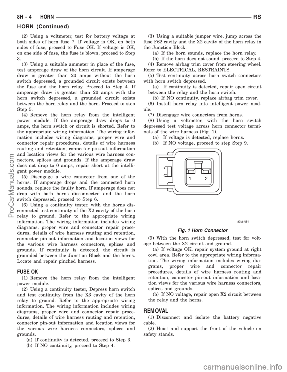
minal (Fig. 1).
(3) Depress the horn switch, battery voltage
should be present.
(4) If no voltage, refer toHORNS WILL NOT
SOUND. If voltage is OK, go to step Step 5.
(5) Using ohmmeter, test ground wire for continu-
ity to ground.
(6) If no ground repair as necessary.
(7) If wires test OK and horn does not sound,
replace horn.
HORNS SOUND CONTINUOUSLY
CAUTION:
Continuous sounding of horns may cause relay to
fail.
The horn switch (membrane) sometimes can be the
cause without the switch being depressed.
(1) Remove the horn relay from the intelligent
power module.
(2) Using a continuity tester, test continuity from
the X3 cavity of the horn relay to ground. Refer to
the appropriate wiring information. The wiring infor-
mation includes wiring diagrams, proper wire and
connector repair procedures, details of wire harnessrouting and retention, connector pin-out information
and location views for the various wire harness con-
nectors, splices and grounds.
(a) If continuity is detected, proceed to step Step
3.
(b) If NO continuity, replace the horn relay.
(3) Remove the airbag trim cover from the steering
wheel and disengage horn connector.
(4) Install horn relay into intelligent power mod-
ule.
(a) If horn does not sound, replace airbag trim
cover.
(b) If horn sounds, repair grounded X3 circuit
from intelligent power module to clockspring in the
steering column. Refer to the appropriate wiring
information. The wiring information includes wir-
ing diagrams, proper wire and connector repair
procedures, details of wire harness routing and
retention, connector pin-out information and loca-
tion views for the various wire harness connectors,
splices and grounds.HORNS WILL NOT SOUND
Check horn fuse#8intheintelligent power mod-
ule. If fuse is blown, check for a shorted switch in the
airbag module. and refer to FUSE BLOWN section. If
fuse is OK, refer to FUSE OK section.
FUSE BLOWN
(1) Verify condition of battery terminals and volt-
age, (Refer to 8 - ELECTRICAL/BATTERY SYSTEM
- DIAGNOSIS AND TESTING). If battery connec-
tions and battery charge is OK proceed to Step 2.
RSHORN8H-3
HORN (Continued)
ProCarManuals.com
Page 447 of 2321
(2) Using a voltmeter, test for battery voltage at
both sides of horn fuse 7. If voltage is OK, on both
sides of fuse, proceed to Fuse OK. If voltage is OK,
on one side of fuse, the fuse is blown, proceed to Step
3.
(3) Using a suitable ammeter in place of the fuse,
test amperage draw of the horn circuit. If amperage
draw is greater than 20 amps without the horn
switch depressed, a grounded circuit exists between
the fuse and the horn relay. Proceed to Step 4. If
amperage draw is greater than 20 amps with the
horn switch depressed, a grounded circuit exists
between the horn relay and the horn. Proceed to step
Step 5.
(4) Remove the horn relay from the intelligent
power module. If the amperage draw drops to 0
amps, the horn switch or circuit is shorted. Refer to
the appropriate wiring information. The wiring infor-
mation includes wiring diagrams, proper wire and
connector repair procedures, details of wire harness
routing and retention, connector pin-out information
and location views for the various wire harness con-
nectors, splices and grounds. If the amperage draw
does not drop to 0 amps, repair short at the intelli-
gent power module.
(5) Disengage a wire connector from one of the
horns. If amperage drops and the connected horn
sounds, replace the faulty horn. If amperage does not
drop with both horns disconnected and the horn
switch depressed, proceed to Step 6.
(6) Using a continuity tester, with the horns dis-
connected test continuity of the X2 cavity of the horn
relay to ground. Refer to the appropriate wiring
information. The wiring information includes wiring
diagrams, proper wire and connector repair proce-
dures, details of wire harness routing and retention,
connector pin-out information and location views for
the various wire harness connectors, splices and
grounds. If continuity is detected, the circuit is
grounded between the Junction Block and the horns.
Locate and repair pinched harness.
FUSE OK
(1) Remove the horn relay from the intelligent
power module.
(2) Using a continuity tester, Depress horn switch
and test continuity from the X3 cavity of the horn
relay to ground. Refer to the appropriate wiring
information. The wiring information includes wiring
diagrams, proper wire and connector repair proce-
dures, details of wire harness routing and retention,
connector pin-out information and location views for
the various wire harness connectors, splices and
grounds.
(a) If continuity is detected, proceed to Step 3.
(b) If NO continuity, proceed to Step 4.(3) Using a suitable jumper wire, jump across the
fuse F62 cavity and the X2 cavity of the horn relay in
the Junction Block.
(a) If the horn sounds, replace the horn relay.
(b) If the horn does not sound, proceed to Step 4.
(4) Remove airbag trim cover from steering wheel.
Refer to ELECTRICAL, RESTRAINTS.
(5) Test continuity across horn switch connectors
with horn switch depressed.
(a) If continuity is detected, repair open circuit
between the relay and the horn switch.
(b) If NO continuity, replace airbag trim cover.
(6) Install horn relay into intelligent power mod-
ule.
(7) Disengage wire connectors from horns.
(8) Using a voltmeter, with the horn switch
depressed test voltage across horn connector termi-
nals of the wire harness (Fig. 1).
(a) If voltage is detected, replace horns.
(b) If NO voltage, proceed to step Step 9.
(9) With the horn switch depressed, test for volt-
age between the X2 circuit and ground.
(a) If voltage OK, repair system ground at right
cowl area. Refer to the appropriate wiring informa-
tion. The wiring information includes wiring dia-
grams, proper wire and connector repair
procedures, details of wire harness routing and
retention, connector pin-out information and loca-
tion views for the various wire harness connectors,
splices and grounds.
(b) If NO voltage, repair open X2 circuit between
the relay and the horns.
REMOVAL
(1) Disconnect and isolate the battery negative
cable.
(2) Hoist and support the front of the vehicle on
safety stands.
Fig. 1 Horn Connector
8H - 4 HORNRS
HORN (Continued)
ProCarManuals.com