2001 DODGE TOWN AND COUNTRY horn
[x] Cancel search: hornPage 448 of 2321
(3) From behind the front fascia and forward of
the left front wheel, disconnect the wire connectors
from horn.
(4) Remove the mounting bracket attaching nut
from the bottom of radiator closure panel. Do not
remove the horn from mounting bracket.
(5) Separate the horn(s) from vehicle.
INSTALLATION
(1) Install the horns to the vehicle.
(2) Install the mounting bracket nut.
(3) Reconnect the wire connectors to the horns.
(4) Lower the vehicle.
(5) Reconnect the battery negative cable.
HORN RELAY
DIAGNOSIS AND TESTING
(1) Remove horn relay.
(2) Using ohmmeter, test between relay connector
terminals 85 to 86 for 70 to 75 ohms resistance. If
resistance not OK, replace relay.
(3) Test for continuity between ground and termi-
nal 85 of horn relay.
(a) When the horn switch is not depressed, no
continuity should be present.
(b) Continuity to ground when horn switch is
depressed.
(c) If continuity is not correct repair horn
switch or wiring as necessary, refer to the appro-
priate wiring information. The wiring information
includes wiring diagrams, proper wire and connec-
tor repair procedures, details of wire harness rout-
ing and retention, connector pin-out information
and location views for the various wire harness
connectors, splices and grounds.
(4) Using voltmeter, test voltage at:
(a) Terminals 30 and 86 of the horn relay to
body ground.(b) If NO voltage check fuse 8 of the intelligent
power module.
(c) If incorrect voltage, repair as necessary. Refer
to the appropriate wiring information. The wiring
information includes wiring diagrams, proper wire
and connector repair procedures, details of wire
harness routing and retention, connector pin-out
information and location views for the various wire
harness connectors, splices and grounds.
(5) Insert a jumper wire between terminal 30 and
87 of the intelligent power module.
(a) If horn sounds replace relay.
(b) If the horn does not sound, install horn relay
and refer to Horn Test.
REMOVAL
(1) Disconnect and isolate the battery negative
cable.
(2) Remove cover from the intelligent power mod-
ule.
(3) Remove relay from intelligent power module.
INSTALLATION
(1) Push relay into intelligent power module.
(2) Install cover.
(3) Reconnect battery negative cable.
HORN SWITCH
DESCRIPTION
The horn switch is molded into the airbag trim
cover. The horn switch can not be serviced separately.
For service procedures, refer to ELECTRICAL /
RESTRAINTS.
RSHORN8H-5
HORN (Continued)
ProCarManuals.com
Page 476 of 2321
DAYTIME RUNNING LAMPS
Power is reduced using pulse-width modulation to
the high beams, where by the power is switched on
and off rapidly instead of remaining on continuously.
The duration and interval of the power pulses is pro-
grammed into the Front Control Module (FCM).
HEADLAMP SYSTEM
The headlamp system will default to headlamps
ON position when ignition switch is ON and when an
open or short circuit failure occurs on the headlamp
switch input. The system will return to normal oper-
ation when the open or short is repaired. A fault will
be reported by the BCM when a failure occurs on the
dimmer or headlamp switch input.
If the exterior lamps are ON and the headlamp
switch is in any position other than OFF or AUTO
and with the ignition switch OFF (LOCK) after 3
minutes the BCM sends a message via J1850 to the
FCM informing the FCM to turn off the headlamps,
park lamps and fog lamps. This feature prevents the
vehicle battery from being discharged when the vehi-
cle lights have been left ON.
HEADLAMP TIME DELAY SYSTEM
The headlamp time delay system is activated by
turning the headlamps ON (high or low beam) while
the engine is running, turning the ignition switch
OFF, and then turning the headlamp switch OFF
within 45 seconds. The system will not activate if
more than 45 seconds elapse between ignition switch
OFF and headlamp switch OFF. The BCM will allow
the headlamps to remain ON for 90 seconds (config-
urable) before they automatically turn off (If the key
is in the ignition during the headlamp time delay
mode, then both the headlamps and park lamps
(including panel dimming) will be ON). Refer to the
Owner's Manual for more information.
If the headlamp switch is in the Auto Headlamp
Position, the headlamps are ON due to the night sig-
nal from the CMTC and the ignition switch is in any
position other than run/start, the BCM shall enter a
90 second (configurable) Auto Headlamps time delay
mode. If the key is in the ignition during the head-
lamp time delay mode, then both the headlamps and
park lamps (including panel dimming) will be ON. If
the key is not in the ignition, then only the head-
lamps will be ON. The BCM will allow the head-
lamps to remain ON for 90 seconds before they
automatically turn OFF. Refer to the Owner's Man-
ual for more information.
LAMP OUTAGE
If one or more of the following lamps (Low and/or
High beams) are out, then a ªlamps outº indicator
located in the cluster will illuminate.
OPTICAL HORN/HIGH BEAMS
When the multifunction switch is pulled to the first
detent (optical horn) signal, the headlamps are ON,
key-in the ignition the BCM shall send a message via
J1850 to the FCM to turn on the headlamps drivers
to illuminate all four filaments (Low and High
beams). When the multifunction switch is pulled to
the second detent (high beam) signal and the head-
lamps are ON, the BCM shall send a message via
J1850 to the FCM to turn on the headlamps drivers.
The High Beams are illuminated and the Low Beams
and Fog Lamps (if ON) are extinguished. If the head-
lamps were in the high beam configuration when
power was removed from the headlamps, the head-
lamps will be configured as low beam the next time
they are activated.
DIAGNOSIS AND TESTING
WARNING: EYE PROTECTION SHOULD BE USED
WHEN SERVICING GLASS COMPONENTS. PER-
SONAL INJURY CAN RESULT.
CAUTION: Do not touch the glass of halogen bulbs
with fingers or other possibly oily surface, reduced
bulb life will result. Do not use bulbs other than
those indicated in the Bulb Application table. Dam-
age to lamp and/or Daytime Running Lamp Module
can result. Do not use fuses, circuit breakers or
relays having greater amperage value than indi-
cated on the fuse panel or in the Owners Manual.
When a vehicle experiences problems with the
headlamp system, verify the condition of the battery
connections, fuses, charging system, headlamp bulbs,
wire connectors, relay, high beam switch, dimmer
switch, and headlamp switch. Refer to the appropri-
ate wiring information. The wiring information
includes wiring diagrams, proper wire and connector
repair procedures, details of wire harness routing
and retention, connector pin-out information and
location views for the various wire harness connec-
tors, splices and grounds.
Each vehicle is equipped with various lamp assem-
blies. A good ground is necessary for proper lighting
operation. Grounding is provided by the lamp socket
when it comes in contact with the metal body, or
through a separate ground wire.
When changing lamp bulbs check the socket for
corrosion. If corrosion is present, clean it with a wire
brush.
When it is necessary to remove components to ser-
vice another, it should not be necessary to apply
excessive force or bend a component to remove it.
Before damaging a trim component, verify hidden
fasteners or captured edges are not holding the com-
ponent in place.
RSLAMPS/LIGHTING - EXTERIOR8L-3
LAMPS/LIGHTING - EXTERIOR (Continued)
ProCarManuals.com
Page 488 of 2321
OPERATION - TURN SIGNAL SYSTEM
Lane change signaling is actuated by applying par-
tial turn signal stalk movement toward the direction
desired until the indicator lamps flashes in the
instrument cluster. When the switch stalk is released
the stalk will spring back into the neutral position
turning OFF the turn signal.
With the ignition switch ON and the turn signal
switch stalk actuated left or right, current flows
through the:
²Multi-function switch
²Body Control Module
²Integrated Power Module (IPM)
²Turn indicator lamp
²Front and rear turn signal bulbs.
A chime will sound after the vehicle has traveled a
distance of approximately 0.5 mile and a speed of 15
mph, with the turn signal ON.
DIAGNOSIS AND TESTING - MULTI-FUNCTION
SWITCH
To test turn signal, headlamp beam select and opti-
cal horn portion of the multi-function switch:
(1) Remove the multi-function switch, refer to
Electrical, Lamps/Lighting - Exterior, Multi-Function
Switch, Removal, and Installation.
(2) Using an ohmmeter check the continuity read-
ings between multi-function switch pins. Refer to
Wiring Diagrams for proper pin numbers and the
table.
MULTI-FUNCTION SWITCH CONTINUITY
SWITCH POSITION CONTINUITY BETWEEN
LEFT 2 AND 3
RIGHT 2 AND 3
OPTICAL HORN 2 AND 4
HI BEAM 2 AND 4
REMOVAL
(1) Disconnect and isolate battery negative cable.
(2) Remove upper and lower steering column
shrouds. Refer to Steering, Column, Shroud,
Removal.
(3) Disconnect wire connector from back of multi-
function switch.
(4) Remove screws holding multi-function switch to
steering column adapter collar.
(5) Remove the multi-function switch.
INSTALLATION
(1) Position the switch on to the steering column.
(2) Install the two retaining screws.
(3) Connect the wire harness connector.
(4) Install the upper and lower steering column
shrouds. Refer to Steering, Column, Shroud, Installa-
tion.
(5) Connect the battery negative cable.
PARK/TURN SIGNAL LAMP
REMOVAL
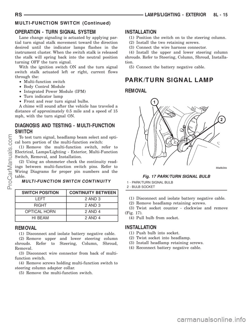
(1) Disconnect and isolate battery negative cable.
(2) Remove headlamp retaining screws.
(3) Twist socket counter - clockwise and remove
(Fig. 17).
(4) Pull bulb from socket.
INSTALLATION
(1) Push bulb into socket.
(2) Twist socket into headlamp.
(3) Install headlamp retaining screws.
(4) Reconnect battery negative cable.
Fig. 17 PARK/TURN SIGNAL BULB
1 - PARK/TURN SIGNAL BULB
2 - BULB SOCKET
RSLAMPS/LIGHTING - EXTERIOR8L-15
MULTI-FUNCTION SWITCH (Continued)
ProCarManuals.com
Page 510 of 2321
recall memory settings when the Driver 1 or Driver 2
push buttons of the memory switch on the driver side
front door trim panel are depressed.
²SOUND HORN ON LOCK?- The options
include Yes and No. The default is No. When Yes is
selected, a short horn chirp will provide an audible
confirmation when the RKE receiver recognizes a
valid Lock signal from an RKE transmitter. When No
is selected, no horn chirp will occur with the RKE
Lock event. This feature may be selected indepen-
dent of theFLASH LIGHTS WITH LOCKS?pro-
grammable feature.
²FLASH LIGHTS WITH LOCKS?- The options
include Yes and No. The default is Yes. When Yes is
selected, a single flash of the hazard warning lamps
will provide an optical confirmation when the RKE
receiver recognizes a valid Lock signal from an RKE
transmitter, and two flashes of the same lamps will
occur when the RKE receiver recognizes a valid
Unlock signal from an RKE transmitter. When No is
selected, no lamp flash will occur with the RKE Lock
or Unlock event. This feature may be selected inde-
pendent of theSOUND HORN ON LOCK?pro-
grammable feature.
²HEADLAMP DELAY =- The options include
Off, 30 Sec, 60 Sec, and 90 Sec. The default is 90 Sec.
When a time interval is selected, the headlamps will
remain on for that length of time when the head-
lamps are turned off after the ignition is turned off,
or if the Auto mode is selected on vehicles with the
Auto Headlamps option. When Off is selected, the
headlamp delay feature is disabled.
²HEADLAMPS ON WITH WIPERS?- This pro-
grammable feature only applies to vehicles equipped
with the optional Auto Headlamps. The options
include Yes and No. The default is No. When Yes is
selected, the headlamps will turn on automatically
when the windshield wipers are turned on. The head-
lamps will turn off when the wipers are turned off,
as long as the headlamp switch is in the Auto or Off
positions. When No is selected, the headlamps will
only turn on if manually selected or if the Auto mode
is selected and the outside ambient light levels dic-
tate that they should be on.
²POWER ACCESSORY DELAY?- The options
include Yes and No. The default is Yes. When No is
selected, the accessory powered components will turn
off automatically when the ignition key is turned off.
When Yes is selected, the accessory powered compo-
nents will remain on for 45 seconds when the igni-
tion key is turned off.
REMOVAL
(1) Disconnect and isolate the battery negative
cable.(2) Remove overhead console. Refer to Overhead
Console Removal and Installation in this section(Re-
fer to 8 - ELECTRICAL/OVERHEAD CONSOLE -
REMOVAL) .
(3) Remove the ten screws holding the EVIC mod-
ule in the overhead console.
(4) Remove EVIC module from console assembly.
INSTALLATION
(1) Position the EVIC module in the overhead con-
sole.
(2) Install the ten screws holding the EVIC module
in the overhead console.
(3) Install the overhead console. Refer to Overhead
Console Removal and Installation in this section.
(4) Connect the battery negative cable.
NOTE: If a new EVIC module has been installed, the
compass will have to be calibrated and the variance
set. Refer to Compass Variation Adjustment and
Compass Calibration in the Service Procedures sec-
tion of this group for the procedures.
COMPASS/MINI-TRIP
COMPUTER
DESCRIPTION
The Compass Mini-Trip Computer (CMTC) and
Compass Temperature (CT) computer are modules
located in the overhead console. Vehicles are
equipped with either the CMTC or the CT computers
not both. The CMTC is different in the fact that it is
equipped with the mini-trip feature. The CMTC, CT
consists of a electronic control module with a vacuum
fluorescent display (VFD) and function switches. The
CMTC, CT consists of a electronic module that dis-
plays compass, trip computer (CMTC only), and tem-
perature features. Actuating the STEP push button
(CMTC only) will cause the CMTC to change mode of
operation when ignition is ON. Actuating the STEP
push button (CMTC only) will cause the CMTC to
change mode of operation when ignition is ON.
Example:
²Average miles per gallon (ECO)
²Distance to empty (DTE)
²Instant miles per gallon (ECO)
²Trip odometer (ODO)
²Elapsed time (ET)
²Off
Actuating the C/T push button will cause the
CMTC, CT to change to Compass/Temperature dis-
play.
RSOVERHEAD CONSOLE8M-9
ELECTRONIC VEHICLE INFO CENTER (Continued)
ProCarManuals.com
Page 552 of 2321
POWER LOCKS
TABLE OF CONTENTS
page page
POWER LOCKS
DESCRIPTION...........................39
OPERATION.............................40
DOOR LOCK MOTOR
DIAGNOSIS AND TESTING.................41
DOOR LOCK MOTOR....................41
DOOR LOCK SWITCH
DESCRIPTION...........................41
DIAGNOSIS AND TESTING.................41
DOOR LOCK SWITCH...................41
REMOVAL..............................42
INSTALLATION...........................42
KEYLESS ENTRY TRANSMITTER
STANDARD PROCEDURE..................42
HORN CHIRP PREFERENCE..............42BATTERY REPLACEMENT................42
SPECIFICATIONS........................42
REMOTE KEYLESS ENTRY MODULE
DESCRIPTION...........................43
OPERATION.............................43
DIAGNOSIS AND TESTING.................43
REMOTE KEYLESS ENTRY...............43
STANDARD PROCEDURE..................43
PROGRAMMING RKE MODULE............43
REMOVAL..............................43
INSTALLATION...........................44
SLIDING DOOR LOCK MOTOR
REMOVAL..............................44
INSTALLATION...........................44
POWER LOCKS
DESCRIPTION
POWER DOOR LOCK SYSTEM
The front doors, sliding door(s) and liftgate are
equipped with actuator motors to lock or unlock the
latch mechanisms. The door lock actuator motor is
not serviced separately from the door latch, except
for the sliding door(s).
AUTOMATIC DOOR LOCKS
The vehicle comes with two options for power door
locks:
²Rolling automatic lock (ENABLE), doors auto-
matically lock at approximately at 25.7 Km/h (16
mph).
²No rolling automatic lock (DISABLE), doors do
not automatically lock when the vehicle is moving.
DOOR LOCK INHIBIT
The BCM cancels out the door lock switch actua-
tion, when the key is in the Ignition Switch and
either front door is open.
Pressing the key fob RKE lock/unlock under these
conditions results in normal lock/unlock activation.
CENTRAL LOCKING
If equipped with Vehicle Theft Security System
(VTSS), all the doors can be locked with the key by
using any of the door lock cylinders. Turning the key
to the lock position will lock all the doors. If a sliding
door is open when this is done, the sliding door will
lock when it is closed.
DOOR LOCK CIRCUIT PROTECTION
The door lock system is protected by a 40 amp fuse
located in the IPM. The BCM receives lock/unlock
input and will turn on the appropriate drivers and
provide a voltage level to the door lock motor for a
specific time. The IPM is located along the side of the
vehicle battery in the engine compartment.
RSPOWER LOCKS8N-39
ProCarManuals.com
Page 553 of 2321
REMOTE KEYLESS ENTRY SYSTEM
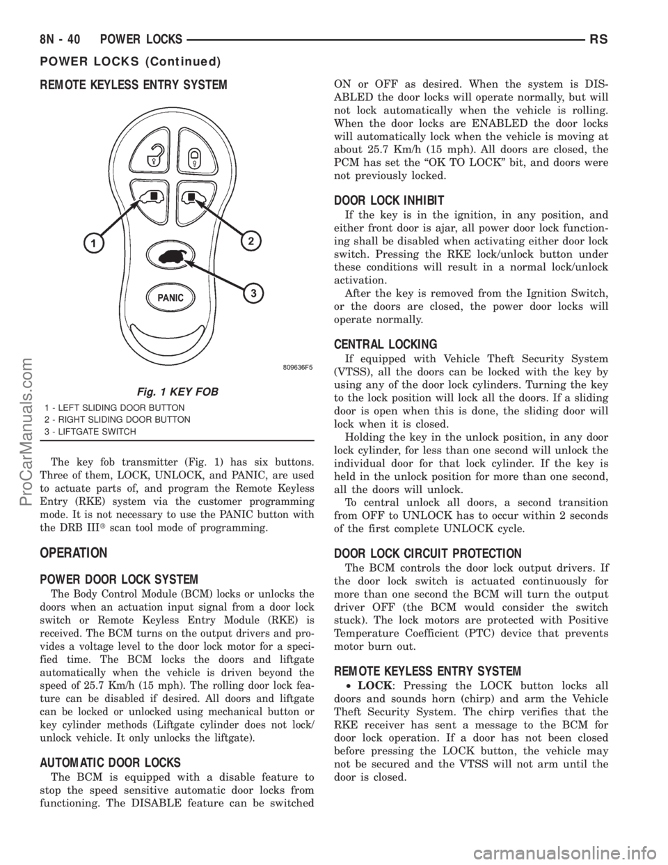
The key fob transmitter (Fig. 1) has six buttons.
Three of them, LOCK, UNLOCK, and PANIC, are used
to actuate parts of, and program the Remote Keyless
Entry (RKE) system via the customer programming
mode. It is not necessary to use the PANIC button with
the DRB IIItscan tool mode of programming.
OPERATION
POWER DOOR LOCK SYSTEM
The Body Control Module (BCM) locks or unlocks the
doors when an actuation input signal from a door lock
switch or Remote Keyless Entry Module (RKE) is
received. The BCM turns on the output drivers and pro-
vides a voltage level to the door lock motor for a speci-
fied time. The BCM locks the doors and liftgate
automatically when the vehicle is driven beyond the
speed of 25.7 Km/h (15 mph). The rolling door lock fea-
ture can be disabled if desired. All doors and liftgate
can be locked or unlocked using mechanical button or
key cylinder methods (Liftgate cylinder does not lock/
unlock vehicle. It only unlocks the liftgate).
AUTOMATIC DOOR LOCKS
The BCM is equipped with a disable feature to
stop the speed sensitive automatic door locks from
functioning. The DISABLE feature can be switchedON or OFF as desired. When the system is DIS-
ABLED the door locks will operate normally, but will
not lock automatically when the vehicle is rolling.
When the door locks are ENABLED the door locks
will automatically lock when the vehicle is moving at
about 25.7 Km/h (15 mph). All doors are closed, the
PCM has set the ªOK TO LOCKº bit, and doors were
not previously locked.
DOOR LOCK INHIBIT
If the key is in the ignition, in any position, and
either front door is ajar, all power door lock function-
ing shall be disabled when activating either door lock
switch. Pressing the RKE lock/unlock button under
these conditions will result in a normal lock/unlock
activation.
After the key is removed from the Ignition Switch,
or the doors are closed, the power door locks will
operate normally.
CENTRAL LOCKING
If equipped with Vehicle Theft Security System
(VTSS), all the doors can be locked with the key by
using any of the door lock cylinders. Turning the key
to the lock position will lock all the doors. If a sliding
door is open when this is done, the sliding door will
lock when it is closed.
Holding the key in the unlock position, in any door
lock cylinder, for less than one second will unlock the
individual door for that lock cylinder. If the key is
held in the unlock position for more than one second,
all the doors will unlock.
To central unlock all doors, a second transition
from OFF to UNLOCK has to occur within 2 seconds
of the first complete UNLOCK cycle.
DOOR LOCK CIRCUIT PROTECTION
The BCM controls the door lock output drivers. If
the door lock switch is actuated continuously for
more than one second the BCM will turn the output
driver OFF (the BCM would consider the switch
stuck). The lock motors are protected with Positive
Temperature Coefficient (PTC) device that prevents
motor burn out.
REMOTE KEYLESS ENTRY SYSTEM
²LOCK: Pressing the LOCK button locks all
doors and sounds horn (chirp) and arm the Vehicle
Theft Security System. The chirp verifies that the
RKE receiver has sent a message to the BCM for
door lock operation. If a door has not been closed
before pressing the LOCK button, the vehicle may
not be secured and the VTSS will not arm until the
door is closed.
Fig. 1 KEY FOB
1 - LEFT SLIDING DOOR BUTTON
2 - RIGHT SLIDING DOOR BUTTON
3 - LIFTGATE SWITCH
8N - 40 POWER LOCKSRS
POWER LOCKS (Continued)
ProCarManuals.com
Page 554 of 2321
²UNLOCK: Pressing the UNLOCK button once
will unlock the driver's side doors and activate the
illuminated entry system and disarm Vehicle Theft
Security System, if equipped. Pressing the UNLOCK
button twice within five seconds will unlock all doors
and activate the illuminated entry system.
²LEFT SLIDING DOOR: Pressing the LEFT
SLIDING DOOR BUTTON opens/closes the left
power sliding door remotely.
²RIGHT SLIDING DOOR: Pressing the RIGHT
SLIDING DOOR BUTTON opens/closes the right
power sliding door remotely.
²LIFTGATE: Pressing the LIFTGATE BUTTON
opens/closes the liftgate remotely.
²PANIC: Pressing the PANIC button sounds the
horns at half second intervals, flashes the exterior
lamps, and turns ON the interior lamps. The panic
alarm will remain on for three minutes, or until the
PANIC button is actuated again or the ignition
switch is turned to the RUN position.
The Remote Keyless Entry Module is capable of
retaining the transmitter Vehicle Access Code(s)
(VAC) in its memory even after vehicle power has
been interrupted.
NOTE: Additional features available to the customer
are described in the Vehicle Owners Manual.
The RKE system activates the optional memory
seat and mirror system, if equipped. Two primary
key fob transmitters can be programmed to actuate
memory seat and mirror setting 1 or 2. Two addi-
tional key fob transmitters can be added, but they
will not be able to operate the memory seat and mir-
ror system (Refer to 8 - ELECTRICAL/POWER
SEATS - OPERATION) and (Refer to 8 - ELECTRI-
CAL/POWER MIRRORS - OPERATION).
DOOR LOCK MOTOR
DIAGNOSIS AND TESTING - DOOR LOCK
MOTOR
Verify battery condition before testing door lock
motor(s) (Refer to 8 - ELECTRICAL/BATTERY SYS-
TEM/BATTERY - DIAGNOSIS AND TESTING).
To determine which motor is faulty, check each
individual door for electrical lock and unlock or dis-
connect the motor connectors one at a time, while
operating the door lock switch. In the event that
none of the motors work, the problem may be caused
by a shorted motor or a bad switch. Disconnecting
the defective motor will allow the others to work.
To test an individual door lock motor, disconnect
the electrical connector from the motor. To lock the
door, connect a 12 volt power source to the positivepin of the lock motor and a ground wire to the other
pin. Refer to the appropriate wiring information. The
wiring information includes wiring diagrams, proper
wire and connector repair procedures, further details
on wire harness routing and retention, as well as
pin-out and location views for the various wire har-
ness connectors, splices and grounds. To unlock the
door reverse the wire connections at the motor pin
terminals. If these results are NOT obtained, replace
the motor.
DOOR LOCK SWITCH
DESCRIPTION
The Power Door Lock Switch is attached to the
door trim panel with two screws.
DIAGNOSIS AND TESTING - DOOR LOCK
SWITCH
(1) Remove door trim panel. Refer to Body, Door -
Front, Trim Panel, Removal and Installation.
(2) Disconnect wire connector from back of door
lock switch.
(3) Depress switch to LOCK position.
(4) Using an ohmmeter, test switch resistance
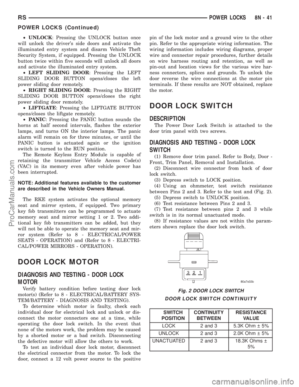
between Pins 2 and 3. Refer to the test and (Fig. 2).
(5) Depress switch to UNLOCK position.
(6) Test resistance between Pins 2 and 3.
(7) Test resistance between pins 2 and 3 while
switch is in its normal unactuated mode.
(8) If resistance values are not within the param-
eters shown replace the door lock switch.
DOOR LOCK SWITCH CONTINUITY
SWITCH
POSITIONCONTINUITY
BETWEENRESISTANCE
VALUE
LOCK 2 and 3 5.3K Ohm 5%
UNLOCK 2 and 3 2.0K Ohm 5%
UNACTUATED 2 and 3 18.3K Ohms
5%
Fig. 2 DOOR LOCK SWITCH
RSPOWER LOCKS8N-41
POWER LOCKS (Continued)
ProCarManuals.com
Page 555 of 2321
REMOVAL
(1) Disconnect and isolate the battery negative
cable.
(2) Remove door trim panel. Refer to Body, Door -
Front, Trim Panel, Removal.
(3) Disconnect wire connector from back of door
lock switch.
(4) Remove two screws to door lock switch.
(5) Remove switch from vehicle.
INSTALLATION
(1) Install the switch into the vehicle.
(2) Install the two screws to door lock switch.
(3) Connect wire connector to back of door lock
switch.
(4) Install door trim panel. Refer to Body, Door -
Front, Trim Panel, Installation.
(5) Connect the battery negative cable.
KEYLESS ENTRY
TRANSMITTER
STANDARD PROCEDURE - HORN CHIRP
PREFERENCE
DISABLING
The horn chirp can be toggled using a DRB IIItor
by using the Remote Keyless Entry (RKE) transmit-
ter.
To DISABLE (cancelling) the horn chirp feature,
press and hold the transmitter LOCK button for a
minimum of four seconds. While pressing the LOCK
button in, press the UNLOCK button. The horn chirp
feature will not function until the above procedure is
repeated.
ENABLING
The horn chirp can be toggled using a DRB IIItor
by using the Remote Keyless Entry (RKE) transmit-
ter.
To ENABLE (reinstate) the horn chirp feature, use
any one of the four key fob transmitters and reverse
the above procedures. It will ENABLE the horn chirp
feature for all transmitters.
STANDARD PROCEDURE - BATTERY
REPLACEMENT
(1) With the transmitter buttons facing down, use
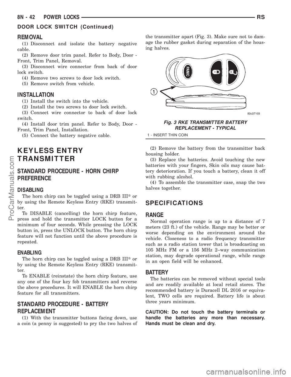
a coin (a penny is suggested) to pry the two halves ofthe transmitter apart (Fig. 3). Make sure not to dam-
age the rubber gasket during separation of the hous-
ing halves.
(2) Remove the battery from the transmitter back
housing holder.
(3) Replace the batteries. Avoid touching the new
batteries with your fingers, Skin oils may cause bat-
tery deterioration. If you touch a battery, clean it off
with rubbing alcohol.
(4) To assemble the transmitter case, snap the two
halves together.
SPECIFICATIONS
RANGE
Normal operation range is up to a distance of 7
meters (23 ft.) of the vehicle. Range may be better or
worse depending on the environment around the
vehicle. Closeness to a radio frequency transmitter
such as a radio station tower that is broadcasting on
105 MHz FM or a 156 MHz 2±way communication
station, may degrade operational range, while range
in an open field will be enhanced.
BATTERY
The batteries can be removed without special tools
and are readily available at local retail stores. The
recommended battery is Duracell DL 2016 or equiva-
lent, TWO cells are required. Battery life is about
three years minimum.
CAUTION: Do not touch the battery terminals or
handle the batteries any more than necessary.
Hands must be clean and dry.
Fig. 3 RKE TRANSMITTER BATTERY
REPLACEMENT - TYPICAL
1 - INSERT THIN COIN
8N - 42 POWER LOCKSRS
DOOR LOCK SWITCH (Continued)
ProCarManuals.com