2001 DODGE TOWN AND COUNTRY airbag
[x] Cancel search: airbagPage 338 of 2321
AUDIO
TABLE OF CONTENTS
page page
AUDIO
DESCRIPTION............................1
OPERATION.............................1
DIAGNOSIS AND TESTING..................1
ANTENNA BODY & CABLE
DESCRIPTION............................3
OPERATION.............................3
DIAGNOSIS AND TESTING..................3
REMOVAL...............................4
INSTALLATION............................4
CD CHANGER
DESCRIPTION............................6
OPERATION.............................6
REMOVAL...............................6
INSTALLATION............................6
CHOKE
DIAGNOSIS AND TESTING..................6
D-PILLAR SPEAKER
REMOVAL...............................6
INSTALLATION............................7
DASH PANEL SPEAKER
REMOVAL...............................7INSTALLATION............................7
DOOR MOUNTED SPEAKER
REMOVAL...............................7
INSTALLATION............................7
QUARTER PANEL SPEAKER
REMOVAL...............................8
INSTALLATION............................8
RADIO
DIAGNOSIS AND TESTING..................8
REMOVAL...............................9
INSTALLATION............................9
RADIO NOISE SUPPRESSION COMPONENTS
DESCRIPTION............................9
OPERATION.............................9
REMOTE SWITCHES
DESCRIPTION...........................10
OPERATION.............................10
DIAGNOSIS AND TESTING.................11
REMOVAL..............................11
INSTALLATION...........................12
AUDIO
DESCRIPTION
There are four different system combinations avail-
able on the RS models. The available radio options
are:
²AM/FM Cassette
²AM/FM Compact Disc with Compact Disc
Changer
²AM/FM Cassette with single Compact Disc
Player
²AM/FM Cassette with Compact Disc Changer
All factory installed radio receivers are stereo Elec-
tronically Tuned Radios (ETR) and include and elec-
tronic digital clock function.
OPERATION
Operating instructions for the factory installed
audio systems can be found in the Owner's Manual
provided with this vehicle.
DIAGNOSIS AND TESTING
WARNING:
ON VEHICLES EQUIPPED WITH AIRBAGS, REFER
TO ELECTRICAL, RESTRAINTS BEFORE ATTEMPT-
ING ANY STEERING WHEEL, STEERING COLUMN,
OR INSTRUMENT PANEL COMPONENT DIAGNOSIS
OR SERVICE. FAILURE TO TAKE THE PROPER
PRECAUTIONS COULD RESULT IN ACCIDENTAL
AIRBAG DEPLOYMENT AND POSSIBLE PERSONAL
INJURY.
RSAUDIO8A-1
ProCarManuals.com
Page 340 of 2321
CONDITION POSSIBLE CAUSE CORRECTION
4. POOR ANTENNA
CONNECTION AT
RADIO OR IN LINE.4. SEAT CONNECTOR.
NO/POOR TAPE
OPERATION.1. FAULTY TAPE. 1. INSERT KNOWN GOOD TAPE AND TEST OPERATION.
2. FOREIGN OBJECTS
BEHIND TAPE DOOR.2. REMOVE FOREIGN OBJECTS AND TEST OPERATION.
3. DIRTY CASSETTE
TAPE HEAD.3. CLEAN HEAD WITH MOPAR CASSETTE HEAD CLEANER.
4. FAULTY TAPE DECK. 4. EXCHANGE OR REPLACE RADIO, IF REQUIRED.
NO COMPACT
DISC
OPERATION1. FAULTY CD. 1. INSERT KNOWN GOOD CD AND TEST OPERATION.
2. FOREIGN MATERIAL
ON CD.2. CLEAN CD AND TEST OPERATION.
3. CONDENSATION ON
CD OR OPTICS.3. ALLOW TEMPERATURE OF VEHICLE INTERIOR TO
STABILIZE AND TEST OPERATION.
4. FAULTY CD PLAYER. 4. EXCHANGE OR REPLACE RADIO, IF REQUIRED.
ANTENNA BODY & CABLE
DESCRIPTION
All models use a fixed-length stainless steel rod-
type antenna mast, installed at the right front fender
of the vehicle. The antenna mast is connected to the
center wire of the coaxial antenna cable, and is not
grounded to any part of the vehicle.
OPERATION
To minimize static, the antenna base must have a
good ground. The coaxial antenna cable shield (the
outer wire mesh of the cable) is grounded to the
antenna base and the radio chassis.
The antenna coaxial cable has an additional dis-
connect, located near the right end of the instrument
panel. This additional disconnect allows the instru-
ment panel assembly to be removed and installed
without removing the radio.
The factory-installed Electronically Tuned Radios
(ETRs) automatically compensate for radio antenna
trim. Therefore, no antenna trimmer adjustment is
required or possible when replacing the receiver or
the antenna.
DIAGNOSIS AND TESTING
WARNING:
ON VEHICLES EQUIPPED WITH AIRBAGS, REFER
TO ELECTRICAL, RESTRAINTS BEFORE ATTEMPT-ING ANY STEERING WHEEL, STEERING COLUMN,
OR INSTRUMENT PANEL COMPONENT DIAGNOSIS
OR SERVICE. FAILURE TO TAKE THE PROPER
PRECAUTIONS COULD RESULT IN ACCIDENTAL
AIRBAG DEPLOYMENT AND POSSIBLE PERSONAL
INJURY.
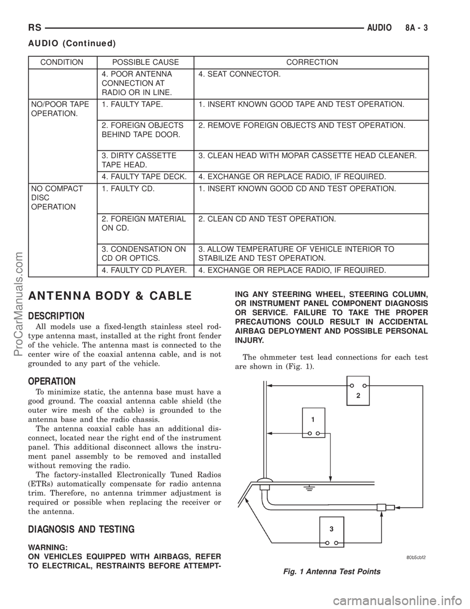
The ohmmeter test lead connections for each test
are shown in (Fig. 1).
Fig. 1 Antenna Test Points
RSAUDIO8A-3
AUDIO (Continued)
ProCarManuals.com
Page 345 of 2321
(4) Connect battery negative cable.
QUARTER PANEL SPEAKER
REMOVAL
(1) Disconnect and isolate the battery negative
cable.
(2) Remove speaker grill by prying away from trim
panel.
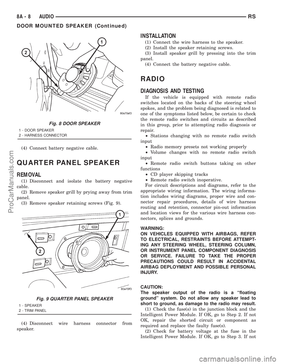
(3) Remove speaker retaining screws (Fig. 9).
(4) Disconnect wire harness connector from
speaker.
INSTALLATION
(1) Connect the wire harness to the speaker.
(2) Install the speaker retaining screws.
(3) Install speaker grill by pressing into the trim
panel.
(4) Connect the battery negative cable.
RADIO
DIAGNOSIS AND TESTING
If the vehicle is equipped with remote radio
switches located on the backs of the steering wheel
spokes, and the problem being diagnosed is related to
one of the symptoms listed below, be certain to check
the remote radio switches and circuits as described
in this group, prior to attempting radio diagnosis or
repair.
²Stations changing with no remote radio switch
input
²Radio memory presets not working properly
²Volume changes with no remote radio switch
input
²Remote radio switch buttons taking on other
functions
²CD player skipping tracks
²Remote radio switch inoperative.
For circuit descriptions and diagrams, refer to the
appropriate wiring information. The wiring informa-
tion includes wiring diagrams, proper wire and con-
nector repair procedures, details of wire harness
routing and retention, connector pin-out information
and location views for the various wire harness con-
nectors, splices and grounds.
WARNING:
ON VEHICLES EQUIPPED WITH AIRBAGS, REFER
TO ELECTRICAL, RESTRAINTS BEFORE ATTEMPT-
ING ANY STEERING WHEEL, STEERING COLUMN,
OR INSTRUMENT PANEL COMPONENT DIAGNOSIS
OR SERVICE. FAILURE TO TAKE THE PROPER
PRECAUTIONS COULD RESULT IN ACCIDENTAL
AIRBAG DEPLOYMENT AND POSSIBLE PERSONAL
INJURY.
CAUTION:
The speaker output of the radio is a ªfloating
groundº system. Do not allow any speaker lead to
short to ground, as damage to the radio may result.
(1) Check the fuse(s) in the junction block and the
Intelligent Power Module. If OK, go to Step 2. If not
OK, repair the shorted circuit or component as
required and replace the faulty fuse(s).
(2) Check for battery voltage at the fuse in the
Intelligent Power Module. If OK, go to Step 3. If not
Fig. 8 DOOR SPEAKER
1 - DOOR SPEAKER
2 - HARNESS CONNECTOR
Fig. 9 QUARTER PANEL SPEAKER
1 - SPEAKER
2 - TRIM PANEL
8A - 8 AUDIORS
DOOR MOUNTED SPEAKER (Continued)
ProCarManuals.com
Page 348 of 2321
DIAGNOSIS AND TESTING
WARNING:
ON VEHICLES EQUIPPED WITH AIRBAGS, REFER
TO ELECTRICAL, RESTRAINTS BEFORE ATTEMPT-
ING ANY STEERING WHEEL, STEERING COLUMN,
OR INSTRUMENT PANEL COMPONENT DIAGNOSIS
OR SERVICE. FAILURE TO TAKE THE PROPER
PRECAUTIONS COULD RESULT IN ACCIDENTAL
AIRBAG DEPLOYMENT AND POSSIBLE PERSONAL
INJURY.
(1) Disconnect and isolate the battery negative
cable. Wait two minutes for the airbag system capac-
itor to discharge before further service.
(2) Remove the remote radio switch(es) from the
steering wheel. (Refer to 8 - ELECTRICAL/AUDIO/
REMOTE SWITCHES - REMOVAL).
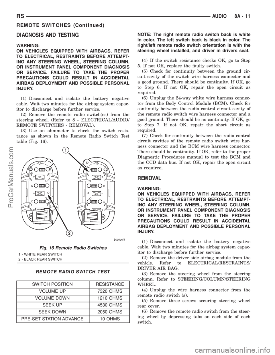
(3) Use an ohmmeter to check the switch resis-
tance as shown in the Remote Radio Switch Test
table (Fig. 16).
REMOTE RADIO SWITCH TEST
SWITCH POSITION RESISTANCE
VOLUME UP 7320 OHMS
VOLUME DOWN 1210 OHMS
SEEK UP 4530 OHMS
SEEK DOWN 2050 OHMS
PRE-SET STATION ADVANCE 10 OHMSNOTE: The right remote radio switch back is white
in color. The left switch back is black in color. The
right/left remote radio switch orientation is with the
steering wheel installed, and driver in drivers seat.
(4) If the switch resistance checks OK, go to Step
5. If not OK, replace the faulty switch.
(5) Check for continuity between the ground cir-
cuit cavity of the switch wire harness connector and
a good ground. There should be continuity. If OK, go
to Step 6. If not OK, repair the open circuit as
required.
(6) Unplug the 24-way white wire harness connec-
tor from the Body Control Module (BCM). Check for
continuity between the radio control circuit cavity of
the remote radio switch wire harness connector and a
good ground. There should be no continuity. If OK, go
to Step 7. If not OK, repair the short circuit as
required.
(7) Check for continuity between the radio control
circuit cavities of the remote radio switch wire har-
ness connector and the BCM wire harness connector.
There should be continuity. If OK, refer to the proper
Diagnostic Procedures manual to test the BCM and
the CCD data bus. If not OK, repair the open circuit
as required.
REMOVAL
WARNING:
ON VEHICLES EQUIPPED WITH AIRBAGS, REFER
TO ELECTRICAL, RESTRAINTS BEFORE ATTEMPT-
ING ANY STEERING WHEEL, STEERING COLUMN,
OR INSTRUMENT PANEL COMPONENT DIAGNOSIS
OR SERVICE. FAILURE TO TAKE THE PROPER
PRECAUTIONS COULD RESULT IN ACCIDENTAL
AIRBAG DEPLOYMENT AND POSSIBLE PERSONAL
INJURY.
(1) Disconnect and isolate the battery negative
cable. Wait two minutes for the airbag system capac-
itor to discharge before further service.
(2) Remove the driver side airbag module from the
vehicle. Refer to ELECTRICAL/RESTRAINTS/
DRIVER AIR BAG.
(3) Remove the steering wheel from the steering
column. Refer to STEERING/COLUMN/STEERING
WHEEL.
(4) Unplug the wire harness connector from the
remote radio switch (s).
(5) Remove three screws securing steering wheel
rear cover.
(6) Remove the remote radio switch from the steer-
ing wheel by depressing tabs on each side of each
switch.
Fig. 16 Remote Radio Switches
1 - WHITE REAR SWITCH
2 - BLACK REAR SWITCH
RSAUDIO8A-11
REMOTE SWITCHES (Continued)
ProCarManuals.com
Page 349 of 2321
NOTE: The right remote radio switch back is white
in color. The left switch back is black in color. The
right/left remote radio switch orientation is with the
steering wheel installed, and driver in drivers seat.
INSTALLATION
WARNING:
ON VEHICLES EQUIPPED WITH AIRBAGS, REFER
TO ELECTRICAL, RESTRAINTS BEFORE ATTEMPT-
ING ANY STEERING WHEEL, STEERING COLUMN,
OR INSTRUMENT PANEL COMPONENT DIAGNOSIS
OR SERVICE. FAILURE TO TAKE THE PROPER
PRECAUTIONS COULD RESULT IN ACCIDENTAL
AIRBAG DEPLOYMENT AND POSSIBLE PERSONAL
INJURY.(1) Install remote radio switch to the steering
wheel.
(2) Install three screws securing steering wheel
rear cover.
(3) Connect the wire harness to the remote radio
switch.
(4) Install the steering wheel. Refer to STEERING/
COLUMN/STEERING WHEEL.
(5) Install the driver side airbag module. Refer to
ELECTRICAL/RESTRAINTS/DRIVER AIRBAG.
(6) Connect the battery negative cable.
8A - 12 AUDIORS
REMOTE SWITCHES (Continued)
ProCarManuals.com
Page 352 of 2321
CHIME/BUZZER
TABLE OF CONTENTS
page page
CHIME/BUZZER
DESCRIPTION............................1
OPERATION.............................1
DIAGNOSIS AND TESTING..................1
CHIME SYSTEM.........................1
DOME LAMP ON CHIME..................2
ENGINE TEMPERATURE CRITICAL CHIME....2EXTERIOR LAMPS ON CHIME..............2
KEY-IN IGNITION CHIME..................2
LOW OIL PRESSURE CHIME...............2
SEAT BELT CHIME.......................3
SEAT BELT LAMP.......................3
TURN SIGNAL ON CHIME.................3
WARNING LAMP ANNOUNCEMENT CHIME....3
CHIME/BUZZER
DESCRIPTION
WARNING: ON VEHICLES EQUIPPED WITH AIR-
BAGS, DISABLE THE AIRBAG SYSTEM BEFORE
ATTEMPTING ANY STEERING WHEEL, STEERING
COLUMN, OR INSTRUMENT PANEL COMPONENT
DIAGNOSIS OR SERVICE. DISCONNECT AND ISO-
LATE THE BATTERY NEGATIVE (GROUND) CABLE,
THEN WAIT TWO MINUTES FOR THE AIRBAG SYS-
TEM CAPACITOR TO DISCHARGE BEFORE PER-
FORMING FURTHER DIAGNOSIS OR SERVICE. THIS
IS THE ONLY SURE WAY TO DISABLE THE AIRBAG
SYSTEM. FAILURE TO TAKE THE PROPER PRE-
CAUTIONS COULD RESULT IN ACCIDENTAL AIR-
BAG DEPLOYMENT AND POSSIBLE PERSONAL
INJURY.
The chime/buzzer system provides the driver with
warning chimes for:
²Seat Belt
²Exterior Lamps ON
²Key-In Ignition
²Engine Temperature Critical
²Turn Signals ON
²Dome Lamp ON
²Low Oil Pressure
²High Speed Warning
²Warning Lamp Announcement
²Key-In Accessory
OPERATION
The Chime/Buzzer Warning System is diagnosed
using a DRBIIItscan tool. Refer to the proper Body
Diagnostic Procedures Manual.
DIAGNOSIS AND TESTING - CHIME SYSTEM
NO TONE WHEN IGNITION SWITCH IS TURNED ON
AND DRIVER'S SEAT BELT IS NOT BUCKLED.
(1) Using a DRBIIItscan tool, actuate chime
(BCM actuates).
(2) Using a voltmeter, check for voltage:
(a) BCM has two battery feeds at pin 1 and pin
5 of the 6±way connector.
(b) Pin 5 of the (BX2) 32 way connector of the
BCM for ignition feed.
(c) Check voltage (PX2) connector, pin 34 for 12v.
(d) If voltage OK, go to step Step 3
(e) If NO voltage repair as necessary. Refer to
the appropriate wiring information. The wiring
information includes wiring diagrams, proper wire
and connector repair procedures, further details on
wire harness routing and retention, as well as pin-
out and location views for the various wire harness
connectors, splices and grounds.
(3) Check driver's seat belt buckle switch input
(form ORC) for a closed circuit when not buckled. If
input not seen, look for open in wiring or switch. The
switch is grounded when belt is not buckled.
(4) Verify PCI data bus communication between
ORC and BCM.
NO FASTEN SEAT BELT LAMP WHEN IGNITION
SWITCH IS TURNED ON.
(1) Check for burned out lamp.
(2) Using a voltmeter check for voltage at the clus-
ter conncctor:
(a) Pin 2 of the mechanical instrument cluster
for battery feed.
(b) Pin 11 of the mechanical instrument cluster
for ignition voltage.
(3) Repair as necessary.
RSCHIME/BUZZER8B-1
ProCarManuals.com
Page 354 of 2321

²Engine running at 420 to 480 rpm for 10 sec-
onds
²Oil pressure switch closed to ground for (1 sec-
ond minimum, 2 seconds maximum)
Chime rate: 168 to 192 chimes per minute.
DIAGNOSIS AND TESTING - SEAT BELT CHIME
The seat belt chime will sound for 4 to 8 seconds,
when the ignition is turned on and the driver's seat
belt is not buckled (seat belt switch is closed to
ground). This is a reminder to the driver to buckle
the seat belt. The seat belt lamp is controlled by the
ORC. The cluster will also bulb check the seat belt
warning lamp for 6 seconds. Buckling the driver's
seat belt before the time out has expired will cause
the chime to stop immediately. Chime rate: 38 to 62
chimes per minute but the lamp will remain on until
6 seconds have expired.
To test the seat belt warning system, the ignition
switch must be in the OFF position for 1 minute
before starting the test. Turn the ignition switch to
the on position with the driver's seat belt not buck-
led. The seat belt warning lamp should light and the
chime should sound 4 to 8 seconds.
DIAGNOSIS AND TESTING - SEAT BELT LAMP
The seat belt lamp in the instrument cluster sig-
nals the vehicle passengers to fasten their seat belts.
The seat belt lamp is illuminated directly by the
instrument cluster for 6 seconds after the instrument
cluster receives the message from the ORC. The seat
belt lamp is therefore illuminated for 6 seconds
whenever the ignition switch is moved to run/start
position.
(1) While ignition is off, the seat belt lamp will not
be illuminated.
(2) The ignition power feed status will be updated
every 250 milliseconds or on change.
(3) This lamp will be checked by the instrument
cluster for 6 seconds with every run/start cycle of the
ignition switch.
DIAGNOSIS AND TESTING - TURN SIGNAL ON
CHIME
The turn signal on chime will warn the driver that
the turn signals have been left on. When the body
control module receives a turn signal input for 1/4.0
mile, vehicle speed is greater than 24 km/h (15 mph),
the chime will sound continuously until the turn sig-nal is turned OFF. If vehicle speed drops below 24
km/h (15 mph) prior to the warning being activated,
the accumulated distance traveled will be reset. The
turn signal chime is not activated when the emer-
gency flashers are turned on. Chime rate: 50612
chimes per minute.
For the turn signal warning system to operate:
²Must have input from either the right or left
turn signal lamps. Creates a voltage change between
0 and battery voltage.
²The vehicle speed sensor sends a message to the
Powertrain Control Module that vehicle has exceeded
24 km/h (15 mph) for 1/4.0 mile).
²When the above two conditions are met, the
chime will sound. The chime will stop when no fur-
ther voltage change is detected.
²If hazard warning signals are pulsing, no chime
will sound.
²If speed drops below 24 km/h (15 mph) before
the warning is issued, the warning will not be issued
and the distance counter will be reset.
²If turn signal lamps are not working properly,
the chime will not sound.
²When using the scan tool, refer to the proper
Body Diagnostic Manual for the procedure.
DIAGNOSIS AND TESTING - WARNING LAMP
ANNOUNCEMENT CHIME
The warning lamp announcement chime will warn
the driver to scan the instrument cluster to observe
which warning lamp is illuminated. Whenever the
volts, low fuel, airbag, door ajar or gate ajar lamps
are first illuminated, the chime will sound one tone.
The door/liftgate ajar warning lamp announcement
chime sounds only if the vehicle speed is above 4
m.p.h.
Two seconds after ignition switch is turned ON or
until the seat belt warning chime ends, all warning
announcement chimes will be consolidated into one
warning announcement. This will occur 2 seconds
after the seat belt warning chime ends. If a warning
announcement should occur while another warning
chime in progress (turn signal, low oil pressure or
high speed warnings), no additional chimes will
sound after the chime in progress ends. All associ-
ated lamps will be illuminated, and the active chime
will be the warning announcement.
RSCHIME/BUZZER8B-3
CHIME/BUZZER (Continued)
ProCarManuals.com
Page 362 of 2321
(2) Reconnect the 24±way electrical and the pump/
motor connector. (Fig. 2)
(3) Install the battery tray (Refer to 8 - ELECTRI-
CAL/BATTERY SYSTEM/TRAY - INSTALLATION).
(4) Install the screw securing the coolant filler
neck to the battery tray.
(5) Reconnect the vacuum hose to the coolant tank
built into the battery tray.
(6) Install the battery (Refer to 8 - ELECTRICAL/
BATTERY SYSTEM/BATTERY - INSTALLATION).
(7) Reconnect the battery cables.
(8) Connect a DRBIIItto the vehicle and initialize
the system.
DATA LINK CONNECTOR
DESCRIPTION
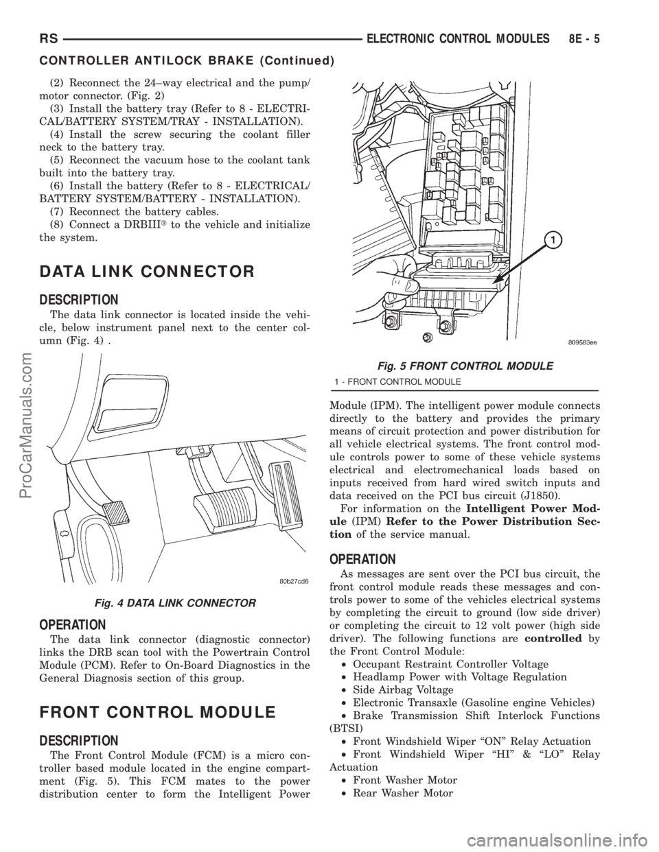
The data link connector is located inside the vehi-
cle, below instrument panel next to the center col-
umn (Fig. 4) .
OPERATION
The data link connector (diagnostic connector)
links the DRB scan tool with the Powertrain Control
Module (PCM). Refer to On-Board Diagnostics in the
General Diagnosis section of this group.
FRONT CONTROL MODULE
DESCRIPTION
The Front Control Module (FCM) is a micro con-
troller based module located in the engine compart-
ment (Fig. 5). This FCM mates to the power
distribution center to form the Intelligent PowerModule (IPM). The intelligent power module connects
directly to the battery and provides the primary
means of circuit protection and power distribution for
all vehicle electrical systems. The front control mod-
ule controls power to some of these vehicle systems
electrical and electromechanical loads based on
inputs received from hard wired switch inputs and
data received on the PCI bus circuit (J1850).
For information on theIntelligent Power Mod-
ule(IPM)Refer to the Power Distribution Sec-
tionof the service manual.
OPERATION
As messages are sent over the PCI bus circuit, the
front control module reads these messages and con-
trols power to some of the vehicles electrical systems
by completing the circuit to ground (low side driver)
or completing the circuit to 12 volt power (high side
driver). The following functions arecontrolledby
the Front Control Module:
²Occupant Restraint Controller Voltage
²Headlamp Power with Voltage Regulation
²Side Airbag Voltage
²Electronic Transaxle (Gasoline engine Vehicles)
²Brake Transmission Shift Interlock Functions
(BTSI)
²Front Windshield Wiper ªONº Relay Actuation
²Front Windshield Wiper ªHIº & ªLOº Relay
Actuation
²Front Washer Motor
²Rear Washer Motor
Fig. 4 DATA LINK CONNECTOR
Fig. 5 FRONT CONTROL MODULE
1 - FRONT CONTROL MODULE
RSELECTRONIC CONTROL MODULES8E-5
CONTROLLER ANTILOCK BRAKE (Continued)
ProCarManuals.com