2001 DODGE TOWN AND COUNTRY fuel reserve
[x] Cancel search: fuel reservePage 22 of 2321

LUBRICATION & MAINTENANCE
TABLE OF CONTENTS
page page
LUBRICATION & MAINTENANCE
SPECIFICATIONS.........................1
INTERNATIONAL SYMBOLS
DESCRIPTION............................1
PARTS & LUBRICANT RECOMMENDATION
STANDARD PROCEDURE...................2
LUBRICANT CLASSIFICATIONS.............2
PARTS AND LUBRICANT
RECOMMENDATIONS....................2
FLUID TYPES
DESCRIPTION............................3
OPERATION.............................7
FLUID FILL/CHECK LOCATIONS
DESCRIPTION............................7MAINTENANCE SCHEDULES
DESCRIPTION............................7
HOISTING
STANDARD PROCEDURE..................16
HOISTING............................16
JUMP STARTING
STANDARD PROCEDURE..................16
JUMP STARTING.......................16
TOWING
STANDARD PROCEDURE..................17
TOWING RECOMMENDATIONS............17
LUBRICATION &
MAINTENANCE
SPECIFICATIONS
SPECIFICATIONS - FLUID CAPACITIES
DESCRIPTION SPECIFICATION
Fuel Tank 75 L (20 gal.)
Engine Oil* - 2.4L 4.7 L (5.0 qts.)
Engine Oil* - 3.3/3.8L 4.0 L (4.5 qts.)
Cooling System** - 2.4L 10.7 L (11.4 qts.)
Cooling System** -
3.3/3.8L without Rear
Heater12.6 L (13.4 qts.)
Cooling System** -
3.3/3.8L with Rear Heater15.4 L (16.3 qts.)
Automatic Transaxle -
Service Fill3.8 L (4.0 qts.)
Automatic Transaxle -
31TH Overhaul Fill8.6 L (9.1 qts.)
Automatic Transaxle -
41TE Overhaul Fill9.2 L (9.7 qts.)
AWD Power Transfer Unit 1.15 L (2.4 pts.)
Power Steering 1.2 L (2.5 pts.)
AWD Bi-directional
Overrunning Clutch0.575 L (1.22 pts.)
DESCRIPTION SPECIFICATION
AWD Rear Carrier 0.7 L (1.48 pts.)
*(includes oil filter)
**(includes heater and recovery/reserve bottle)
INTERNATIONAL SYMBOLS
DESCRIPTION
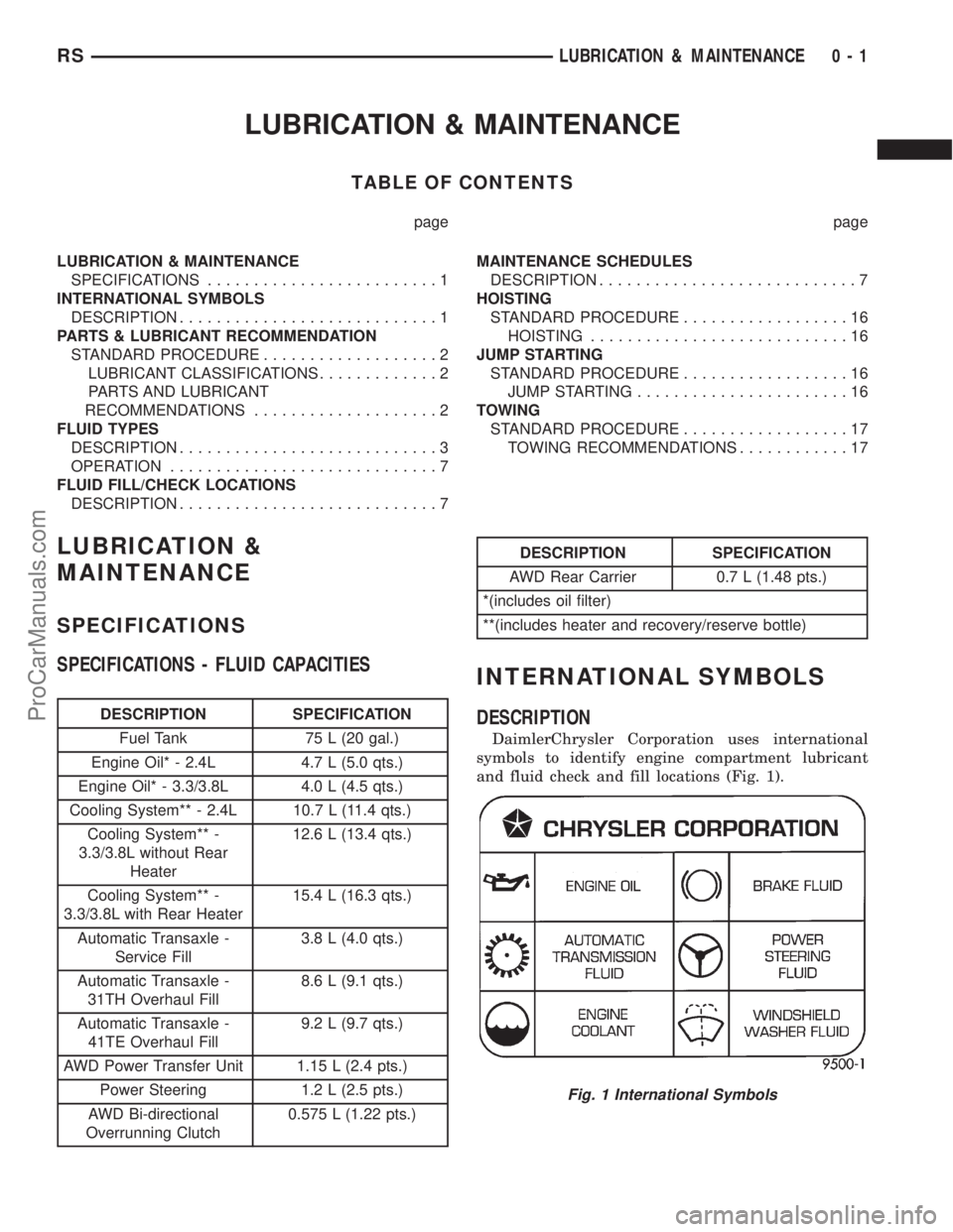
DaimlerChrysler Corporation uses international
symbols to identify engine compartment lubricant
and fluid check and fill locations (Fig. 1).
Fig. 1 International Symbols
RSLUBRICATION & MAINTENANCE0-1
ProCarManuals.com
Page 40 of 2321

LUBRICATION & MAINTENANCE - RG - 2.5 L TURBO
DIESEL
TABLE OF CONTENTS
page page
LUBRICATION & MAINTENANCE - RG - 2.5 L
TURBO DIESEL
SPECIFICATIONS.........................1
INTERNATIONAL SYMBOLS
DESCRIPTION............................2
FLUID TYPES
DESCRIPTION............................2
FLUID FILL/CHECK LOCATIONS
DESCRIPTION............................5
MAINTENANCE SCHEDULES
DESCRIPTION............................5HOISTING
STANDARD PROCEDURE...................7
HOISTING.............................7
JUMP STARTING
STANDARD PROCEDURE...................8
JUMP STARTING........................8
TOWING
STANDARD PROCEDURE...................8
TOWING RECOMMENDATIONS.............8
LUBRICATION &
MAINTENANCE - RG - 2.5 L
TURBO DIESEL
SPECIFICATIONS
SPECIFICATIONS - FLUID CAPACITIES
DESCRIPTION SPECIFICATION
Fuel Tank 75 L (20 gal.)
Fuel Tank (Diesel) 75 L (20 gal.)
Engine Oil* - 2.4 L 4.7 L (5.0 qts.)
Engine Oil* - 3.3 L 4.0 L (4.5 qts.)
Engine Oil* - 2.5 L 5.22 L (5.52 qts.)
Cooling System** - 2.4 L 10.7 L (11.4 qts.)
Cooling System** - 3.3 L
without Auxiliary Heater12.6 L (13.4 qts.)
Cooling System** - 3.3 L
with Auxiliary Heater15.4 L (16.3 qts.)
Cooling System** - 2.5 L
Turbo Diesel without
Auxiliary Heater13.8 L (14.6 qts.)
DESCRIPTION SPECIFICATION
Cooling System** - 2.5 L
Turbo Diesel with
Auxiliary Heater16.6 L (17.5 qts.)
Automatic Transaxle -
Service Fill3.8 L (4.0 qts.)
Automatic Transaxle -
31TH Overhaul Fill8.6 L (9.1 qts.)
Automatic Transaxle -
41TE Overhaul Fill9.2 L (9.7 qts.)
Manual Transaxle (T850
5-speed)2.4-2.7 L (2.5-2.9 qts.)
AWD Power Transfer Unit 1.15 L (2.4 pts.)
Power Steering 1.2 L (2.5 pts.)
AWD Bi-directional
Overrunning Clutch0.575 L (1.22 pts.)
AWD Rear Carrier 0.7 L (1.48 pts.)
*(includes oil filter)
**(includes heater and recovery/reserve bottle)
RGLUBRICATION & MAINTENANCE - RG - 2.5 L TURBO DIESEL0a-1
ProCarManuals.com
Page 1322 of 2321

(7) Attach front engine mount bracket to lower
radiator support. Torque to 54N´m (40 ft. lbs.)
(8) Connect cabin heater coolant hose.
(9) Connect exhaust pipe to the turbocharger
downpipe flange. Torque to 28 N´m (250 in. lbs.)
(10) Connect reverse lamp electrical connector at
transmission.
(11) Connect both shifter cables (Refer to 21 -
TRANSMISSION/TRANSAXLE/MANUAL/GEAR
SHIFT CABLE - INSTALLATION).
(12) Connect the clutch slave cylinder quick dis-
connect connector (RHD only)(Refer to 6 - CLUTCH/
SLAVE CYLINDER - INSTALLATION).
(13) Install engine harness into bracket on trans-
mission.
(14) Lower vehicle.
(15) Connect fuel supply and return lines.
(16) Connect A/C lines to A/C compressor. Torque
to 23N´m (17 ft. lbs.)
(17) Route engine wiring harnes to proper location.
(18) Connect engine harness ground cables to
engine block
(19) Connect starter solenoid electrical connector
and battery feed wire to starter. Torque to 10N´m (90
in. lbs.)
(20) Connect A/C compressor, injection pump, glow
plugs, and coolant temperature sensor electrical con-
nectors.
(21) Connect generator electrical connector. Torque
to 9N´m (75 in. lbs.)
(22) Connect the fuel injector, fuel pressure sensor,
boost pressure/intake air temp sensor, cam sensor,
and egr solenoid electrical connectors (Fig. 9).
(23) Connect egr solenoid vacuum supply line to
brake boost vacuum supply line.
(24) Connect brake booster vacuum supply line.
(25) Connect heater core return hose to coolant
pipe.
(26) Connect lower radiator hose to engine (Fig. 8).
(27) Install charger air cooler inlet hose (Fig. 7).
(28) Install charge air cooler outlet hose (Fig. 7).
(29) Connect upper radiator hose to engine (Fig.
8).
(30) Install battery shield.
(31) Install coolant reserve pressure container
(Refer to 7 - COOLING/ENGINE/COOLANT RECOV-
ERY PRESS CONTAINER - INSTALLATION).
(32) Install power steering reservoir and bracket
(Fig. 5).
(33) Raise vehicle
(34) Connect oil pressure sensor, oil temperature
sensor, engine speed sensor, and vehicle speed sensor
electrical connector (Fig. 10).(35) Install suspension cradle in vehicle (Refer to
13 - FRAME & BUMPERS/FRAME/ENGINE CRA-
DLE CROSSMEMBER - INSTALLATION).
(36) Install both axle shaft assemblies (Refer to 3 -
DIFFERENTIAL & DRIVELINE/HALF SHAFT -
INSTALLATION).
(37) Connect the power steering supply, pressure,
and return lines to power steering pump (Fig. 5).
(38) Install the power steering line brackets on oil
pan (Fig. 5).
(39) Install lower splash shield and side panels.
(40) Install both front wheel and tire assemblies.
(41) Lower vehicle.
(42) Install air cleaner housing, MAF sensor, and
air intake tube assembly (Fig. 4).
(43) Refill transmission to proper level (Refer to 21
- TRANSMISSION/TRANSAXLE/MANUAL/FLUID -
STANDARD PROCEDURE).
(44) Refill engine coolant (Refer to 7 - COOLING/
ENGINE/COOLANT - STANDARD PROCEDURE).
(45) Recharge A/C system (Refer to 24 - HEATING
& AIR CONDITIONING/PLUMBING/REFRIGER-
ANT - STANDARD PROCEDURE) .
(46) Install engine cover (Refer to 9 - ENGINE -
INSTALLATION) (Fig. 3).
(47) Connect negative battery cable.
INSTALLATION - ENGINE COVER
(1) Install engine cover on engine.
(2) Install the engine cover mounting bolts (Fig.
11).
SPECIFICATIONS
SPECIFICATIONS - 2.5L COMMON RAIL
DIESEL ENGINE
ENGINE SPECIFICATIONS
DESCRIPTION SPECIFICATION
Type R2516C
Number of Cylinders 4
Bore 92 mm
Stroke 94 mm
Displacement 2499.5cc
Injection Order 1-3-4-2
Compression Ratio 17.5:1 ( 0.5)
Maximum Power 103kW (140 HP) @ 4000
RPM
Peak Torque 340Nm (34.6 kgm) @
1800 RPM
RGENGINE 2.5L TURBO DIESEL9a-7
ENGINE 2.5L TURBO DIESEL (Continued)
ProCarManuals.com