2001 DODGE TOWN AND COUNTRY key fob battery
[x] Cancel search: key fob batteryPage 515 of 2321
POWER LIFTGATE SYSTEM
DESCRIPTION
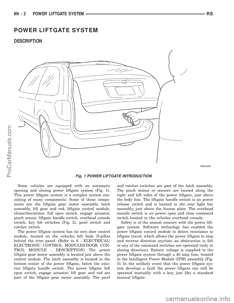
Some vehicles are equipped with an automatic
opening and closing power liftgate system (Fig. 1).
This power liftgate system is a complex system con-
sisting of many components. Some of these compo-
nents are the liftgate gear motor assembly, latch
assembly, lift gear and rod, liftgate control module,
chime/thermistor, full open switch, engage actuator,
pinch sensor, liftgate handle switch, overhead console
switch, key fob switches (Fig. 2), pawl switch and
ratchet switch.
The power liftgate system has its own door control
module, located on the vehicles left body D-pillar
behind the trim panel. (Refer to 8 - ELECTRICAL/
ELECTRONIC CONTROL MODULES/DOOR CON-
TROL MODULE - DESCRIPTION) The power
liftgate gear motor assembly is located just above the
control module. The latch assembly is located in the
bottom center of the power liftgate, below the exte-
rior liftgate handle switch. The power liftgate full
open switch, engage actuator, lift gear and rod are
part of the liftgate gear motor assembly. The pawland ratchet switches are part of the latch assembly.
The pinch sensor or sensors are located along the
right and left sides of the power liftgate, just above
the body line. The liftgate handle switch is an power
release switch and is located in the rear light bar
assembly, just above the license plate. The overhead
console switch is an power open and close command
switch located in the vehicles overhead console.
Safety is of the utmost concern with the power lift-
gate system. Software technology has enabled the
power liftgate control module to detect resistance to
liftgate travel, which allows the power liftgate to stop
and reverse direction anytime an obstruction is felt
or any of the command switches are operated (only in
closing direction). Battery voltage is supplied to the
power liftgate system through a 40 amp fuse, located
in the Intelligent Power Module (IPM) assembly (Fig.
3). In the unlikely event that the power liftgate sys-
tem develops a fault the power liftgate can still be
operated manually with a key, just like a standard
manual liftgate.
Fig. 1 POWER LIFTGATE INTRODUCTION
8N - 2 POWER LIFTGATE SYSTEMRS
ProCarManuals.com
Page 520 of 2321
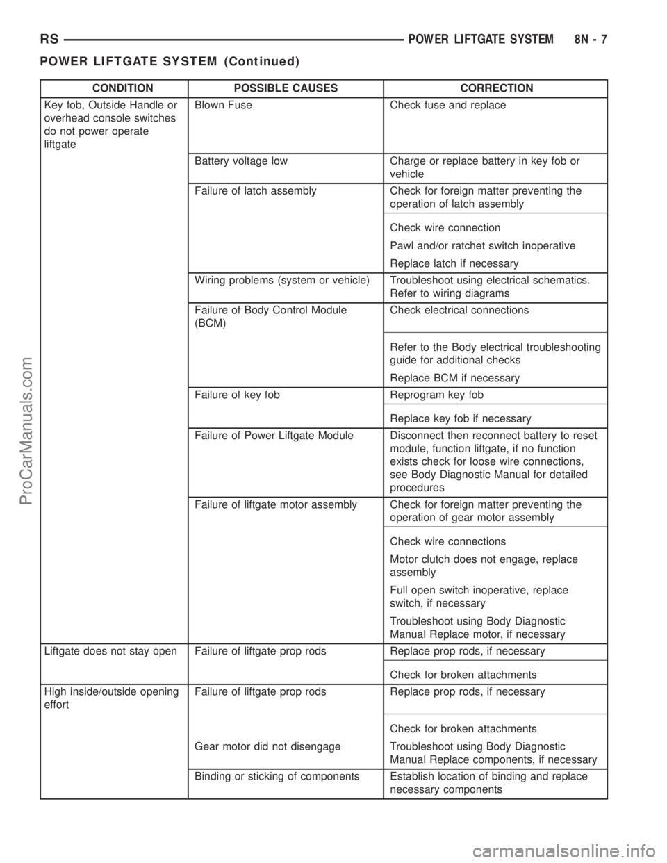
CONDITION POSSIBLE CAUSES CORRECTION
Key fob, Outside Handle or
overhead console switches
do not power operate
liftgateBlown Fuse Check fuse and replace
Battery voltage low Charge or replace battery in key fob or
vehicle
Failure of latch assembly Check for foreign matter preventing the
operation of latch assembly
Check wire connection
Pawl and/or ratchet switch inoperative
Replace latch if necessary
Wiring problems (system or vehicle) Troubleshoot using electrical schematics.
Refer to wiring diagrams
Failure of Body Control Module
(BCM)Check electrical connections
Refer to the Body electrical troubleshooting
guide for additional checks
Replace BCM if necessary
Failure of key fob Reprogram key fob
Replace key fob if necessary
Failure of Power Liftgate Module Disconnect then reconnect battery to reset
module, function liftgate, if no function
exists check for loose wire connections,
see Body Diagnostic Manual for detailed
procedures
Failure of liftgate motor assembly Check for foreign matter preventing the
operation of gear motor assembly
Check wire connections
Motor clutch does not engage, replace
assembly
Full open switch inoperative, replace
switch, if necessary
Troubleshoot using Body Diagnostic
Manual Replace motor, if necessary
Liftgate does not stay open Failure of liftgate prop rods Replace prop rods, if necessary
Check for broken attachments
High inside/outside opening
effortFailure of liftgate prop rods Replace prop rods, if necessary
Check for broken attachments
Gear motor did not disengage Troubleshoot using Body Diagnostic
Manual Replace components, if necessary
Binding or sticking of components Establish location of binding and replace
necessary components
RSPOWER LIFTGATE SYSTEM8N-7
POWER LIFTGATE SYSTEM (Continued)
ProCarManuals.com
Page 530 of 2321
EXTERIOR HANDLE SWITCH
DESCRIPTION
Vehicles equipped with a power liftgate or power
locks utilize a exterior handle switch. The exterior
handle switch is a electronic release switch mounted
to the rear license plate lamp housing assembly,
located just above the license plate. This switch con-
trols the power liftgate release function and is also
capable of reversing the power liftgate when it is in
motion. A full power open cycle cannot be performed
using this switch, only one of the power open com-
mand switches (key fob and overhead console
mounted) can be used to perform a full power open
cycle.
The exterior handle switch is a serviceable compo-
nent. Consult your MoparŸ parts catalog for a spe-
cific part number.
OPERATION
When the exterior handle switch is depressed, with
the liftgate in the closed position. A message is sent
to the Body Control Module (BCM). The Body Con-
trol Module then sends a signal to the power liftgate
control module via the J1850 PCI data bus circuit.
The power liftgate control module then sends a sig-
nal to the power latch mounted actuator, which
moves the liftgate from the primary closed and
latched position to the open and movable position. If
the liftgate is not pulled open once the latch releases
within a few seconds, the latch will cinch closed
again.
REMOVAL
(1) Disconnect and isolate the negative battery
cable.
(2) Open the liftgate and remove the liftgate trim
panel. Refer to the Body section of the service man-
ual for the procedure.
(3) Remove the rear lamp bar assembly from the
vehicle. Refer to the Body section of the service man-
ual for the procedure.
(4) Locate the two wires going to the exterior han-
dle switch. Cut the tie strap and trace the wires to
the large electrical connector and back the wires out
of the large connector and through the grommet.
Refer to the Wiring section of the service manual for
detailed instructions.
(5) Depress the two exterior handle switch retain-
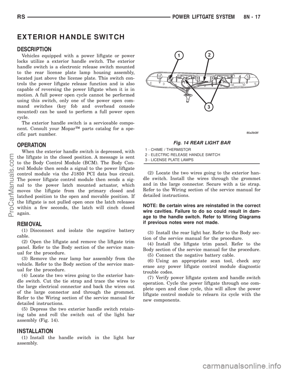
ing tabs and roll the switch out of the light bar
assembly (Fig. 14).
INSTALLATION
(1) Install the handle switch in the light bar
assembly.(2) Locate the two wires going to the exterior han-
dle switch. Install the wires through the grommet
and in the large connector. Secure with a tie strap.
Refer to the Wiring section of the service manual for
detailed instructions.
NOTE: Be certain wires are reinstalled in the correct
wire cavities. Failure to do so could result in dam-
age to the handle switch. Refer to Wiring Diagrams
if previous notes were not made.
(3) Install the rear light bar. Refer to the Body sec-
tion of the service manual for the procedure.
(4) Install the liftgate trim panel. Refer to the
Body section of the service manual for the procedure.
(5) Connect the negative battery cable.
(6) Using an appropriate scan tool, check any
erase any power liftgate control module diagnostic
trouble codes.
(7) Verify power liftgate system and handle switch
operation. Cycle the power liftgate through one com-
plete open and close cycle, this will allow the power
liftgate control module to relearn its cycle with the
new components.
Fig. 14 REAR LIGHT BAR
1 - CHIME / THERMISTOR
2 - ELECTRIC RELEASE HANDLE SWITCH
3 - LICENSE PLATE LAMPS
RSPOWER LIFTGATE SYSTEM8N-17
ProCarManuals.com
Page 533 of 2321
Safety is of the utmost concern with the power
sliding door system. Software technology has enabled
the power sliding door control module to detect resis-
tance to door travel. This allows the power sliding
door to stop and reverse direction any time an
obstruction is felt or any of the command switches
are operated (while closing only). Battery voltage is
supplied to the power sliding door system through a
40 amp fuse, located in the Intelligent Power Module
(IPM) assembly (Fig. 3). The child lockout switch pre-
vents children from opening or actuating the power
sliding door system when desired. In the unlikely
event that the power sliding door system develops a
fault, the power sliding door can still be operated
manually from the interior or exterior door handle,
just like a standard manual sliding door.
The power sliding door control module communi-
cates on the J1850 PCI Data Bus Circuit. Therefore,
the power sliding door control module can generate
and store its own diagnostic trouble codes (DTC). A
diagnostic scan tool, such as the DRB IIItis used to
read and diagnose these trouble codes. Refer to the
Body Diagnostic Manual for a complete list of diag-
nostic routines.
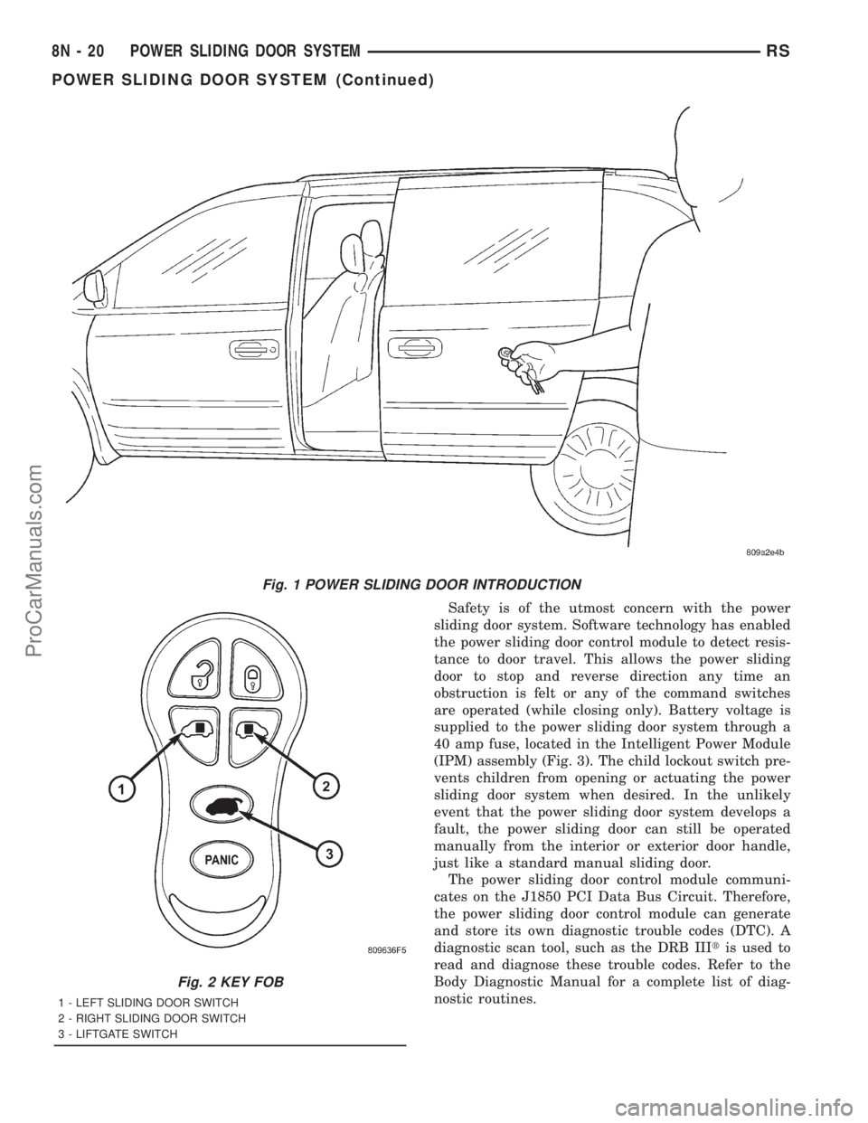
Fig. 1 POWER SLIDING DOOR INTRODUCTION
Fig. 2 KEY FOB
1 - LEFT SLIDING DOOR SWITCH
2 - RIGHT SLIDING DOOR SWITCH
3 - LIFTGATE SWITCH
8N - 20 POWER SLIDING DOOR SYSTEMRS
POWER SLIDING DOOR SYSTEM (Continued)
ProCarManuals.com
Page 539 of 2321
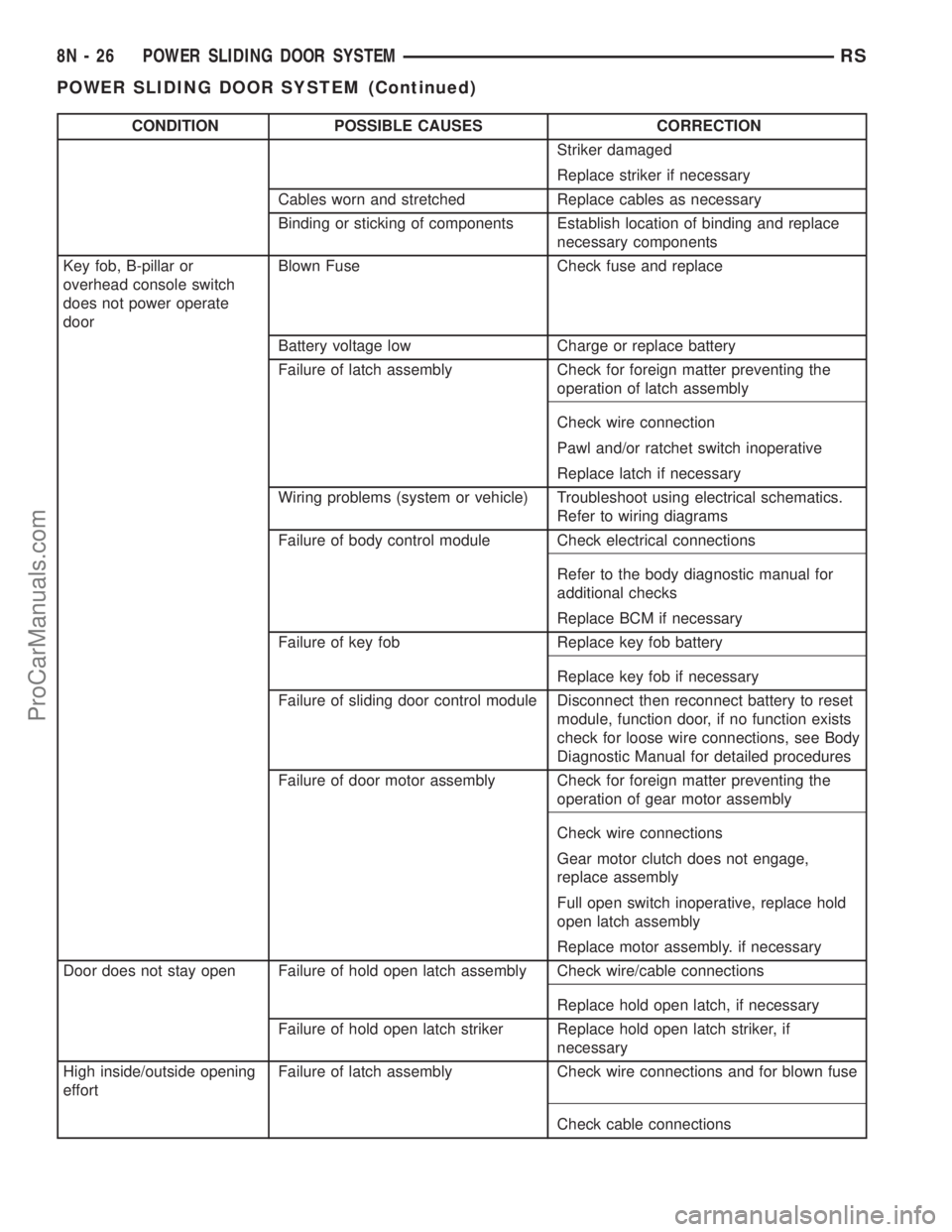
CONDITION POSSIBLE CAUSES CORRECTION
Striker damaged
Replace striker if necessary
Cables worn and stretched Replace cables as necessary
Binding or sticking of components Establish location of binding and replace
necessary components
Key fob, B-pillar or
overhead console switch
does not power operate
doorBlown Fuse Check fuse and replace
Battery voltage low Charge or replace battery
Failure of latch assembly Check for foreign matter preventing the
operation of latch assembly
Check wire connection
Pawl and/or ratchet switch inoperative
Replace latch if necessary
Wiring problems (system or vehicle) Troubleshoot using electrical schematics.
Refer to wiring diagrams
Failure of body control module Check electrical connections
Refer to the body diagnostic manual for
additional checks
Replace BCM if necessary
Failure of key fob Replace key fob battery
Replace key fob if necessary
Failure of sliding door control module Disconnect then reconnect battery to reset
module, function door, if no function exists
check for loose wire connections, see Body
Diagnostic Manual for detailed procedures
Failure of door motor assembly Check for foreign matter preventing the
operation of gear motor assembly
Check wire connections
Gear motor clutch does not engage,
replace assembly
Full open switch inoperative, replace hold
open latch assembly
Replace motor assembly. if necessary
Door does not stay open Failure of hold open latch assembly Check wire/cable connections
Replace hold open latch, if necessary
Failure of hold open latch striker Replace hold open latch striker, if
necessary
High inside/outside opening
effortFailure of latch assembly Check wire connections and for blown fuse
Check cable connections
8N - 26 POWER SLIDING DOOR SYSTEMRS
POWER SLIDING DOOR SYSTEM (Continued)
ProCarManuals.com
Page 552 of 2321
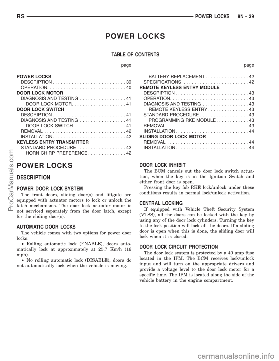
POWER LOCKS
TABLE OF CONTENTS
page page
POWER LOCKS
DESCRIPTION...........................39
OPERATION.............................40
DOOR LOCK MOTOR
DIAGNOSIS AND TESTING.................41
DOOR LOCK MOTOR....................41
DOOR LOCK SWITCH
DESCRIPTION...........................41
DIAGNOSIS AND TESTING.................41
DOOR LOCK SWITCH...................41
REMOVAL..............................42
INSTALLATION...........................42
KEYLESS ENTRY TRANSMITTER
STANDARD PROCEDURE..................42
HORN CHIRP PREFERENCE..............42BATTERY REPLACEMENT................42
SPECIFICATIONS........................42
REMOTE KEYLESS ENTRY MODULE
DESCRIPTION...........................43
OPERATION.............................43
DIAGNOSIS AND TESTING.................43
REMOTE KEYLESS ENTRY...............43
STANDARD PROCEDURE..................43
PROGRAMMING RKE MODULE............43
REMOVAL..............................43
INSTALLATION...........................44
SLIDING DOOR LOCK MOTOR
REMOVAL..............................44
INSTALLATION...........................44
POWER LOCKS
DESCRIPTION
POWER DOOR LOCK SYSTEM
The front doors, sliding door(s) and liftgate are
equipped with actuator motors to lock or unlock the
latch mechanisms. The door lock actuator motor is
not serviced separately from the door latch, except
for the sliding door(s).
AUTOMATIC DOOR LOCKS
The vehicle comes with two options for power door
locks:
²Rolling automatic lock (ENABLE), doors auto-
matically lock at approximately at 25.7 Km/h (16
mph).
²No rolling automatic lock (DISABLE), doors do
not automatically lock when the vehicle is moving.
DOOR LOCK INHIBIT
The BCM cancels out the door lock switch actua-
tion, when the key is in the Ignition Switch and
either front door is open.
Pressing the key fob RKE lock/unlock under these
conditions results in normal lock/unlock activation.
CENTRAL LOCKING
If equipped with Vehicle Theft Security System
(VTSS), all the doors can be locked with the key by
using any of the door lock cylinders. Turning the key
to the lock position will lock all the doors. If a sliding
door is open when this is done, the sliding door will
lock when it is closed.
DOOR LOCK CIRCUIT PROTECTION
The door lock system is protected by a 40 amp fuse
located in the IPM. The BCM receives lock/unlock
input and will turn on the appropriate drivers and
provide a voltage level to the door lock motor for a
specific time. The IPM is located along the side of the
vehicle battery in the engine compartment.
RSPOWER LOCKS8N-39
ProCarManuals.com
Page 554 of 2321
²UNLOCK: Pressing the UNLOCK button once
will unlock the driver's side doors and activate the
illuminated entry system and disarm Vehicle Theft
Security System, if equipped. Pressing the UNLOCK
button twice within five seconds will unlock all doors
and activate the illuminated entry system.
²LEFT SLIDING DOOR: Pressing the LEFT
SLIDING DOOR BUTTON opens/closes the left
power sliding door remotely.
²RIGHT SLIDING DOOR: Pressing the RIGHT
SLIDING DOOR BUTTON opens/closes the right
power sliding door remotely.
²LIFTGATE: Pressing the LIFTGATE BUTTON
opens/closes the liftgate remotely.
²PANIC: Pressing the PANIC button sounds the
horns at half second intervals, flashes the exterior
lamps, and turns ON the interior lamps. The panic
alarm will remain on for three minutes, or until the
PANIC button is actuated again or the ignition
switch is turned to the RUN position.
The Remote Keyless Entry Module is capable of
retaining the transmitter Vehicle Access Code(s)
(VAC) in its memory even after vehicle power has
been interrupted.
NOTE: Additional features available to the customer
are described in the Vehicle Owners Manual.
The RKE system activates the optional memory
seat and mirror system, if equipped. Two primary
key fob transmitters can be programmed to actuate
memory seat and mirror setting 1 or 2. Two addi-
tional key fob transmitters can be added, but they
will not be able to operate the memory seat and mir-
ror system (Refer to 8 - ELECTRICAL/POWER
SEATS - OPERATION) and (Refer to 8 - ELECTRI-
CAL/POWER MIRRORS - OPERATION).
DOOR LOCK MOTOR
DIAGNOSIS AND TESTING - DOOR LOCK
MOTOR
Verify battery condition before testing door lock
motor(s) (Refer to 8 - ELECTRICAL/BATTERY SYS-
TEM/BATTERY - DIAGNOSIS AND TESTING).
To determine which motor is faulty, check each
individual door for electrical lock and unlock or dis-
connect the motor connectors one at a time, while
operating the door lock switch. In the event that
none of the motors work, the problem may be caused
by a shorted motor or a bad switch. Disconnecting
the defective motor will allow the others to work.
To test an individual door lock motor, disconnect
the electrical connector from the motor. To lock the
door, connect a 12 volt power source to the positivepin of the lock motor and a ground wire to the other
pin. Refer to the appropriate wiring information. The
wiring information includes wiring diagrams, proper
wire and connector repair procedures, further details
on wire harness routing and retention, as well as
pin-out and location views for the various wire har-
ness connectors, splices and grounds. To unlock the
door reverse the wire connections at the motor pin
terminals. If these results are NOT obtained, replace
the motor.
DOOR LOCK SWITCH
DESCRIPTION
The Power Door Lock Switch is attached to the
door trim panel with two screws.
DIAGNOSIS AND TESTING - DOOR LOCK
SWITCH
(1) Remove door trim panel. Refer to Body, Door -
Front, Trim Panel, Removal and Installation.
(2) Disconnect wire connector from back of door
lock switch.
(3) Depress switch to LOCK position.
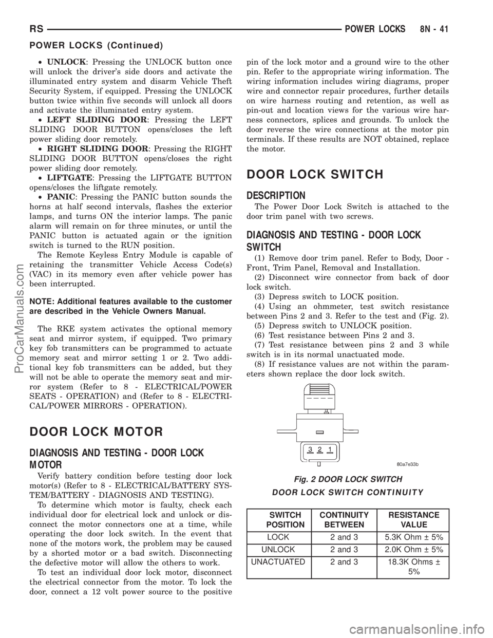
(4) Using an ohmmeter, test switch resistance
between Pins 2 and 3. Refer to the test and (Fig. 2).
(5) Depress switch to UNLOCK position.
(6) Test resistance between Pins 2 and 3.
(7) Test resistance between pins 2 and 3 while
switch is in its normal unactuated mode.
(8) If resistance values are not within the param-
eters shown replace the door lock switch.
DOOR LOCK SWITCH CONTINUITY
SWITCH
POSITIONCONTINUITY
BETWEENRESISTANCE
VALUE
LOCK 2 and 3 5.3K Ohm 5%
UNLOCK 2 and 3 2.0K Ohm 5%
UNACTUATED 2 and 3 18.3K Ohms
5%
Fig. 2 DOOR LOCK SWITCH
RSPOWER LOCKS8N-41
POWER LOCKS (Continued)
ProCarManuals.com
Page 555 of 2321
REMOVAL
(1) Disconnect and isolate the battery negative
cable.
(2) Remove door trim panel. Refer to Body, Door -
Front, Trim Panel, Removal.
(3) Disconnect wire connector from back of door
lock switch.
(4) Remove two screws to door lock switch.
(5) Remove switch from vehicle.
INSTALLATION
(1) Install the switch into the vehicle.
(2) Install the two screws to door lock switch.
(3) Connect wire connector to back of door lock
switch.
(4) Install door trim panel. Refer to Body, Door -
Front, Trim Panel, Installation.
(5) Connect the battery negative cable.
KEYLESS ENTRY
TRANSMITTER
STANDARD PROCEDURE - HORN CHIRP
PREFERENCE
DISABLING
The horn chirp can be toggled using a DRB IIItor
by using the Remote Keyless Entry (RKE) transmit-
ter.
To DISABLE (cancelling) the horn chirp feature,
press and hold the transmitter LOCK button for a
minimum of four seconds. While pressing the LOCK
button in, press the UNLOCK button. The horn chirp
feature will not function until the above procedure is
repeated.
ENABLING
The horn chirp can be toggled using a DRB IIItor
by using the Remote Keyless Entry (RKE) transmit-
ter.
To ENABLE (reinstate) the horn chirp feature, use
any one of the four key fob transmitters and reverse
the above procedures. It will ENABLE the horn chirp
feature for all transmitters.
STANDARD PROCEDURE - BATTERY
REPLACEMENT
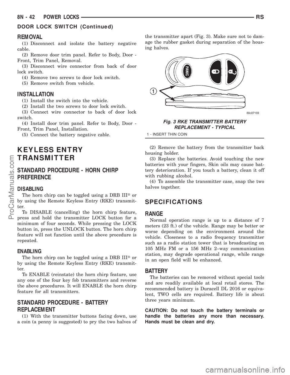
(1) With the transmitter buttons facing down, use
a coin (a penny is suggested) to pry the two halves ofthe transmitter apart (Fig. 3). Make sure not to dam-
age the rubber gasket during separation of the hous-
ing halves.
(2) Remove the battery from the transmitter back
housing holder.
(3) Replace the batteries. Avoid touching the new
batteries with your fingers, Skin oils may cause bat-
tery deterioration. If you touch a battery, clean it off
with rubbing alcohol.
(4) To assemble the transmitter case, snap the two
halves together.
SPECIFICATIONS
RANGE
Normal operation range is up to a distance of 7
meters (23 ft.) of the vehicle. Range may be better or
worse depending on the environment around the
vehicle. Closeness to a radio frequency transmitter
such as a radio station tower that is broadcasting on
105 MHz FM or a 156 MHz 2±way communication
station, may degrade operational range, while range
in an open field will be enhanced.
BATTERY
The batteries can be removed without special tools
and are readily available at local retail stores. The
recommended battery is Duracell DL 2016 or equiva-
lent, TWO cells are required. Battery life is about
three years minimum.
CAUTION: Do not touch the battery terminals or
handle the batteries any more than necessary.
Hands must be clean and dry.
Fig. 3 RKE TRANSMITTER BATTERY
REPLACEMENT - TYPICAL
1 - INSERT THIN COIN
8N - 42 POWER LOCKSRS
DOOR LOCK SWITCH (Continued)
ProCarManuals.com