2001 DODGE TOWN AND COUNTRY battery location
[x] Cancel search: battery locationPage 345 of 2321
(4) Connect battery negative cable.
QUARTER PANEL SPEAKER
REMOVAL
(1) Disconnect and isolate the battery negative
cable.
(2) Remove speaker grill by prying away from trim
panel.
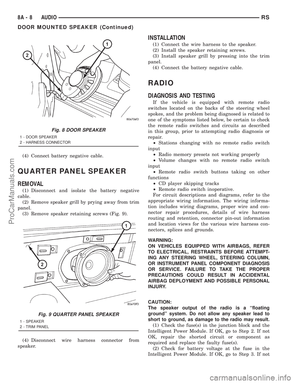
(3) Remove speaker retaining screws (Fig. 9).
(4) Disconnect wire harness connector from
speaker.
INSTALLATION
(1) Connect the wire harness to the speaker.
(2) Install the speaker retaining screws.
(3) Install speaker grill by pressing into the trim
panel.
(4) Connect the battery negative cable.
RADIO
DIAGNOSIS AND TESTING
If the vehicle is equipped with remote radio
switches located on the backs of the steering wheel
spokes, and the problem being diagnosed is related to
one of the symptoms listed below, be certain to check
the remote radio switches and circuits as described
in this group, prior to attempting radio diagnosis or
repair.
²Stations changing with no remote radio switch
input
²Radio memory presets not working properly
²Volume changes with no remote radio switch
input
²Remote radio switch buttons taking on other
functions
²CD player skipping tracks
²Remote radio switch inoperative.
For circuit descriptions and diagrams, refer to the
appropriate wiring information. The wiring informa-
tion includes wiring diagrams, proper wire and con-
nector repair procedures, details of wire harness
routing and retention, connector pin-out information
and location views for the various wire harness con-
nectors, splices and grounds.
WARNING:
ON VEHICLES EQUIPPED WITH AIRBAGS, REFER
TO ELECTRICAL, RESTRAINTS BEFORE ATTEMPT-
ING ANY STEERING WHEEL, STEERING COLUMN,
OR INSTRUMENT PANEL COMPONENT DIAGNOSIS
OR SERVICE. FAILURE TO TAKE THE PROPER
PRECAUTIONS COULD RESULT IN ACCIDENTAL
AIRBAG DEPLOYMENT AND POSSIBLE PERSONAL
INJURY.
CAUTION:
The speaker output of the radio is a ªfloating
groundº system. Do not allow any speaker lead to
short to ground, as damage to the radio may result.
(1) Check the fuse(s) in the junction block and the
Intelligent Power Module. If OK, go to Step 2. If not
OK, repair the shorted circuit or component as
required and replace the faulty fuse(s).
(2) Check for battery voltage at the fuse in the
Intelligent Power Module. If OK, go to Step 3. If not
Fig. 8 DOOR SPEAKER
1 - DOOR SPEAKER
2 - HARNESS CONNECTOR
Fig. 9 QUARTER PANEL SPEAKER
1 - SPEAKER
2 - TRIM PANEL
8A - 8 AUDIORS
DOOR MOUNTED SPEAKER (Continued)
ProCarManuals.com
Page 352 of 2321
CHIME/BUZZER
TABLE OF CONTENTS
page page
CHIME/BUZZER
DESCRIPTION............................1
OPERATION.............................1
DIAGNOSIS AND TESTING..................1
CHIME SYSTEM.........................1
DOME LAMP ON CHIME..................2
ENGINE TEMPERATURE CRITICAL CHIME....2EXTERIOR LAMPS ON CHIME..............2
KEY-IN IGNITION CHIME..................2
LOW OIL PRESSURE CHIME...............2
SEAT BELT CHIME.......................3
SEAT BELT LAMP.......................3
TURN SIGNAL ON CHIME.................3
WARNING LAMP ANNOUNCEMENT CHIME....3
CHIME/BUZZER
DESCRIPTION
WARNING: ON VEHICLES EQUIPPED WITH AIR-
BAGS, DISABLE THE AIRBAG SYSTEM BEFORE
ATTEMPTING ANY STEERING WHEEL, STEERING
COLUMN, OR INSTRUMENT PANEL COMPONENT
DIAGNOSIS OR SERVICE. DISCONNECT AND ISO-
LATE THE BATTERY NEGATIVE (GROUND) CABLE,
THEN WAIT TWO MINUTES FOR THE AIRBAG SYS-
TEM CAPACITOR TO DISCHARGE BEFORE PER-
FORMING FURTHER DIAGNOSIS OR SERVICE. THIS
IS THE ONLY SURE WAY TO DISABLE THE AIRBAG
SYSTEM. FAILURE TO TAKE THE PROPER PRE-
CAUTIONS COULD RESULT IN ACCIDENTAL AIR-
BAG DEPLOYMENT AND POSSIBLE PERSONAL
INJURY.
The chime/buzzer system provides the driver with
warning chimes for:
²Seat Belt
²Exterior Lamps ON
²Key-In Ignition
²Engine Temperature Critical
²Turn Signals ON
²Dome Lamp ON
²Low Oil Pressure
²High Speed Warning
²Warning Lamp Announcement
²Key-In Accessory
OPERATION
The Chime/Buzzer Warning System is diagnosed
using a DRBIIItscan tool. Refer to the proper Body
Diagnostic Procedures Manual.
DIAGNOSIS AND TESTING - CHIME SYSTEM
NO TONE WHEN IGNITION SWITCH IS TURNED ON
AND DRIVER'S SEAT BELT IS NOT BUCKLED.
(1) Using a DRBIIItscan tool, actuate chime
(BCM actuates).
(2) Using a voltmeter, check for voltage:
(a) BCM has two battery feeds at pin 1 and pin
5 of the 6±way connector.
(b) Pin 5 of the (BX2) 32 way connector of the
BCM for ignition feed.
(c) Check voltage (PX2) connector, pin 34 for 12v.
(d) If voltage OK, go to step Step 3
(e) If NO voltage repair as necessary. Refer to
the appropriate wiring information. The wiring
information includes wiring diagrams, proper wire
and connector repair procedures, further details on
wire harness routing and retention, as well as pin-
out and location views for the various wire harness
connectors, splices and grounds.
(3) Check driver's seat belt buckle switch input
(form ORC) for a closed circuit when not buckled. If
input not seen, look for open in wiring or switch. The
switch is grounded when belt is not buckled.
(4) Verify PCI data bus communication between
ORC and BCM.
NO FASTEN SEAT BELT LAMP WHEN IGNITION
SWITCH IS TURNED ON.
(1) Check for burned out lamp.
(2) Using a voltmeter check for voltage at the clus-
ter conncctor:
(a) Pin 2 of the mechanical instrument cluster
for battery feed.
(b) Pin 11 of the mechanical instrument cluster
for ignition voltage.
(3) Repair as necessary.
RSCHIME/BUZZER8B-1
ProCarManuals.com
Page 375 of 2321

(M) Check Engine Lamp (MIL) will illuminate during engine operation if this Diagnostic Trouble Code was recorded.
(G) Generator Lamp Illuminated
GENERIC SCAN
TOOL CODEDRB SCAN TOOL DISPLAY DESCRIPTION OF DIAGNOSTIC TROUBLE CODE
P1682 (G) Charging System Voltage Too Low Battery voltage sense input below target charging voltage
during engine operation and no significant change in voltage
detected during active test of generator output circuit.
P1683 SPD CTRL PWR Relay; or S/C 12v
Driver CKTAn open or shorted condition detected in the speed control
servo power control circuit. (SBECII: ext relay).
P1684 Battery Loss In The Last 50 Starts The battery has been disconnected within the last 50 starts.
P1685 Skim Invalid Key The engine controler has received an invalid key from the
SKIM.
P1686 No SKIM BUS Messages Received No CCD/J1850 messages received from the Smart Key
Immobilizer Module (SKIM).
P1687 No MIC BUS Message No CCD/J1850 messages received from the Mechanical
Instrument Cluster (MIC) module.
P1693 DTC Detected in Companion Module A fault has been generated in the companion engine control
module.
P1694 Fault In Companion Module No CCD/J1850 messages received from the powertrain
control module-Aisin transmission.
P1695 No CCD/J1850 Message From Body
Control ModuleNo CCD/J1850 messages received from the body control
module.
P1696 (M) PCM Failure EEPROM Write Denied Unsuccessful attempt to write to an EEPROM location by the
control module.
P1697 (M) PCM Failure SRI Mile Not Stored Unsuccessful attempt to update Service Reminder Indicator
(SRI or EMR) mileage in the control module EEPROM.
P1698 (M) No CCD/J1850 Message From TCM No CCD/J1850 messages received from the electronic
transmission control module (EATX) or the Aisin transmission
controller.
P1719 Skip Shift Solenoid Circuit An open or shorted condition detected in the transmission
2-3 gear lock-out solenoid control circuit.
P1756 GOV Press Not Equal to Target @
15-20 PSIThe requested pressure and the actual pressure are not
within a tolerance band for the Governor Control System
which is used to regulate governor pressure to control shifts
for 1st, 2nd, and 3rd gear. (Mid Pressure Malfunction)
P1757 GOV Press Not Equal to Target @
15-20 PSIThe requested pressure and the actual pressure are not
within a tolerance band for the Governor Control System
which is used to regulate governor pressure to control shifts
for 1st, 2nd, and 3rd gear (Zero Pressure Malfunction)
P1762 Gov Press Sen Offset Volts Too Low
or HighThe Governor Pressure Sensor input is greater than a
calibration limit or is less than a calibration limit for 3
consecutive park/neutral calibrations.
P1763 Governor Pressure Sensor Volts Too
HiThe Governor Pressure Sensor input is above an acceptable
voltage level.
P1764 Governor Pressure Sensor Volts Too
LowThe Governor Pressure Sensor input is below an acceptable
voltage level.
P1765 Trans 12 Volt Supply Relay CTRL
CircuitAn open or shorted condition is detected in the Transmission
Relay control circuit. This relay supplies power to the TCC>
P1899 (M) P/N Switch Stuck in Park or in Gear Incorrect input state detected for the Park/Neutral switch.
8E - 18 ELECTRONIC CONTROL MODULESRS
POWERTRAIN CONTROL MODULE (Continued)
ProCarManuals.com
Page 382 of 2321

²Output Shaft Speed Sensor
Some examples ofindirect inputsto the TCM
are:
²Engine/Body Identification
²Manifold Pressure
²Target Idle
²Torque Reduction Confirmation
²Speed Control ON/OFF Switch
²Engine Coolant Temperature
²Ambient/Battery Temperature
²Brake Switch Status
²DRB Communication
Based on the information received from these var-
ious inputs, the TCM determines the appropriate
shift schedule and shift points, depending on the
present operating conditions and driver demand.
This is possible through the control of various direct
and indirect outputs.
Some examples of TCMdirect outputsare:
²Transmission Control Relay
²Solenoids (LR/CC, 2/4, OD and UD)
²Vehicle Speed (to PCM)
²Torque Reduction Request (to PCM)
An example of a TCMindirect outputis:
²Transmission Temperature (to PCM)
In addition to monitoring inputs and controlling
outputs, the TCM has other important responsibili-
ties and functions:
²Storing and maintaining Clutch Volume Indices
(CVI)
²Storing and selecting appropriate Shift Sched-
ules
²System self-diagnostics²Diagnostic capabilities (with DRB scan tool)
CLUTCH VOLUME INDEX (CVI)
An important function of the TCM is to monitor
Clutch Volume Index (CVI). CVIs represent the vol-
ume of fluid needed to compress a clutch pack.
The TCM monitors gear ratio changes by monitor-
ing the Input and Output Speed Sensors. The Input,
or Turbine Speed Sensor sends an electrical signal to
the TCM that represents input shaft rpm. The Out-
put Speed Sensor provides the TCM with output
shaft speed information.
By comparing the two inputs, the TCM can deter-
mine transaxle gear ratio. This is important to the
CVI calculation because the TCM determines CVIs
by monitoring how long it takes for a gear change to
occur (Fig. 14).
Gear ratios can be determined by using the DRB
Scan Tool and reading the Input/Output Speed Sen-
sor values in the ªMonitorsº display. Gear ratio can
be obtained by dividing the Input Speed Sensor value
by the Output Speed Sensor value.
For example, if the input shaft is rotating at 1000
rpm and the output shaft is rotating at 500 rpm,
then the TCM can determine that the gear ratio is
Fig. 13 Transmission Control Module (TCM)
Location
1 - TRANSMISSION CONTROL MODULE (TCM)
Fig. 14 Example of CVI Calculation
1 - OUTPUT SPEED SENSOR
2 - OUTPUT SHAFT
3 - CLUTCH PACK
4 - SEPARATOR PLATE
5 - FRICTION DISCS
6 - INPUT SHAFT
7 - INPUT SPEED SENSOR
8 - PISTON AND SEAL
RSELECTRONIC CONTROL MODULES8E-25
TRANSMISSION CONTROL MODULE (Continued)
ProCarManuals.com
Page 385 of 2321
STANDARD PROCEDURE - TCC BREAK-IN
VIEW/RESTART PROCEDURE
The Transmission Control Module (TCM) employs
a strategy which modifies torque converter clutch
(TCC) operation. This strategy conditions the torque
converter clutch disc for optimum converter clutch
engagement and feel throughout the life of the trans-
axle. The cycle inhibits FEMCC until six hours of
PEMCC operation have taken place, or the vehicle
has been driven 6,035 km (3750 miles). The cycle
automatically terminates when either the time or
mileage has been achieved, however, the mileage
may vary slightly from vehicle to vehicle.
The TCC break-in cycle must be restarted using
the DRB Scan Tool, and upon:
²Replacement of TCM on vehicle with less than
6,035 km (3750 miles) or less than 6 hours of
PEMCC operation
²Replacement of torque converter assembly at
any vehicle mileage
NOTE: Failure to restart the TCC Break-In Cycle
upon TCM replacement in vehicles with less than
six hours of PEMCC or less than 6,035 km (3750
miles), or upon torque converter replacement at any
mileage, may result in vehicle shudder during cer-
tain operating conditions.
Procedure
The DRB Scan Tool is required to view and/or
restart the TCC Break-In cycle.
(1) Connect the DRB Scan Tool to the vehicle diag-
nostic connector.
(2) Navigate to ªTCC Break-Inº via Transmission/
Transmission Control Module/Miscellaneous.
(3) View or Start TCC Break-In as prompted by
DRB menu.
REMOVAL
NOTE: If transmission control module is being
replaced with a new or replacement unit, the Pinion
Factor and Quick Learn procedures must be per-
formed. (Refer to 8 - ELECTRICAL/ELECTRONIC
CONTROL MODULES/TRANSMISSION CONTROL
MODULE - STANDARD PROCEDURE) (Refer to 8 -
ELECTRICAL/ELECTRONIC CONTROL MODULES/
TRANSMISSION CONTROL MODULE - STANDARD
PROCEDURE) If vehicle has less than 6,035 km
(3750 miles), the Torque Converter Clutch (TCC)
Break-In Strategy reset procedure must also be per-
formed. (Refer to 8 - ELECTRICAL/ELECTRONIC
CONTROL MODULES/TRANSMISSION CONTROL
MODULE - STANDARD PROCEDURE)(1) Disconnect battery negative cable.
(2) Raise vehicle on hoist.
(3) Remove left front tire/wheel assembly.
(4) Pull back splash shield to gain access to TCM
location.
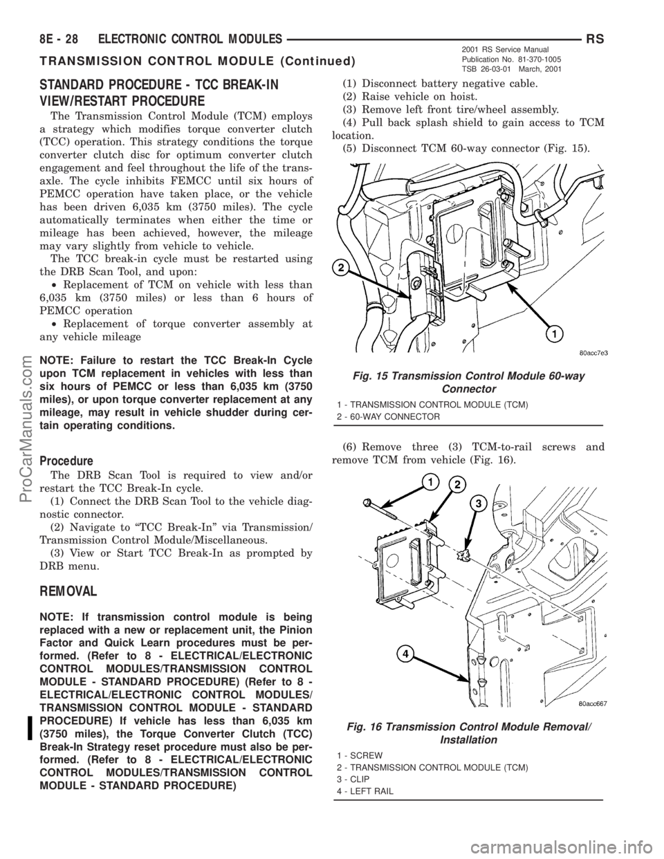
(5) Disconnect TCM 60-way connector (Fig. 15).
(6) Remove three (3) TCM-to-rail screws and
remove TCM from vehicle (Fig. 16).
Fig. 15 Transmission Control Module 60-way
Connector
1 - TRANSMISSION CONTROL MODULE (TCM)
2 - 60-WAY CONNECTOR
Fig. 16 Transmission Control Module Removal/
Installation
1 - SCREW
2 - TRANSMISSION CONTROL MODULE (TCM)
3 - CLIP
4 - LEFT RAIL
8E - 28 ELECTRONIC CONTROL MODULESRS
TRANSMISSION CONTROL MODULE (Continued)
2001 RS Service Manual
Publication No. 81-370-1005
TSB 26-03-01 March, 2001
ProCarManuals.com
Page 389 of 2321
BATTERY SYSTEM
DESCRIPTION
A single 12-volt battery system is standard factory-
installed equipment on this model. All of the compo-
nents of the battery system are located within the
engine compartment of the vehicle. The service infor-
mation for the battery system in this vehicle covers
the following related components, which are covered
in further detail elsewhere in this service manual:
²Battery- The storage battery provides a reli-
able means of storing a renewable source of electrical
energy within the vehicle.
²Battery Cable- The battery cables connect the
battery terminal posts to the vehicle electrical sys-
tem.
²Battery Holddown- The battery holddown
hardware secures the battery in the battery tray in
the engine compartment.
²Battery Thermoguard- The battery thermo-
guard insulates the battery to protect it from engine
compartment temperature extremes.
²Battery Tray- The battery tray provides a
secure mounting location in the vehicle for the bat-
tery and an anchor point for the battery holddown
hardware.
For battery system maintenance schedules and
jump starting procedures, see the owner's manual in
the vehicle glove box. Optionally, refer to Lubrication
and Maintanance for the recommended battery main-
tenance schedules and for the proper battery jump
starting procedures. While battery charging can be
considered a maintenance procedure, the battery
charging procedures and related information are
located in the standard procedures section of this ser-
vice manual. This was done because the battery must
be fully-charged before any battery system diagnosis
or testing procedures can be performed. Refer to
Standard procedures for the proper battery charging
procedures.
OPERATION
The battery system is designed to provide a safe,
efficient, reliable and mobile means of delivering and
storing electrical energy. This electrical energy is
required to operate the engine starting system, as
well as to operate many of the other vehicle acces-sory systems for limited durations while the engine
and/or the charging system are not operating. The
battery system is also designed to provide a reserve
of electrical energy to supplement the charging sys-
tem for short durations while the engine is running
and the electrical current demands of the vehicle
exceed the output of the charging system. In addition
to delivering, and storing electrical energy for the
vehicle, the battery system serves as a capacitor and
voltage stabilizer for the vehicle electrical system. It
absorbs most abnormal or transient voltages caused
by the switching of any of the electrical components
or circuits in the vehicle.
DIAGNOSIS AND TESTING - BATTERY SYSTEM
The battery, starting, and charging systems in the
vehicle operate with one another and must be tested
as a single complete system. In order for the engine
to start and the battery to charge properly, all of the
components that are used in these systems must per-
form within specifications. It is important that the
battery, starting, and charging systems be thoroughly
tested and inspected any time a battery needs to be
charged or replaced. The cause of abnormal battery
discharge, overcharging or early battery failure must
be diagnosed and corrected before a battery is
replaced and before a vehicle is returned to service.
The service information for these systems has been
separated within this service manual to make it eas-
ier to locate the specific information you are seeking.
However, when attempting to diagnose any of these
systems, it is important that you keep their interde-
pendency in mind.
The diagnostic procedures used for the battery,
starting, and charging systems include the most
basic conventional diagnostic methods, to the more
sophisticated On-Board Diagnostics (OBD) built into
the Powertrain Control Module (PCM). Use of an
induction-type milliampere ammeter, a volt/ohmme-
ter, a battery charger, a carbon pile rheostat (load
tester) and a 12-volt test lamp may be required. All
OBD-sensed systems are monitored by the PCM.
Each monitored circuit is assigned a Diagnostic Trou-
ble Code (DTC). The PCM will store a DTC in elec-
tronic memory for any failure it detects. Refer to
Charging System for the proper charging system on-
board diagnostic test procedures.
8F - 2 BATTERY SYSTEMRS
ProCarManuals.com
Page 394 of 2321
material protrude from the top of the molded plastic
battery case to provide the means for connecting the
battery to the vehicle electrical system. The battery
positive terminal post is visibly larger in diameter
than the negative terminal post, for easy identification.
The lettersPOS
andNEGare also molded into the
top of the battery case adjacent to their respective
positive and negative terminal posts for additional
identification confirmation. Refer toBattery Cables
in the index of this service manual for the location of
more information on the battery cables that connect
the battery to the vehicle electrical system.
This battery is designed to provide a safe, efficient
and reliable means of storing electrical energy in a
chemical form. This means of energy storage allows
the battery to produce the electrical energy required
to operate the engine starting system, as well as to
operate many of the other vehicle accessory systems
for limited durations while the engine and/or the
charging system are not operating. The battery is
made up of six individual cells that are connected in
series. Each cell contains positively charged plate
groups that are connected with lead straps to the
positive terminal post, and negatively charged plate
groups that are connected with lead straps to the
negative terminal post. Each plate consists of a stiff
mesh framework or grid coated with lead dioxide
(positive plate) or sponge lead (negative plate). Insu-
lators or plate separators made of a non-conductive
material are inserted between the positive and nega-
tive plates to prevent them from contacting or short-
ing against one another. These dissimilar metal
plates are submerged in a sulfuric acid and water
solution called an electrolyte.
Some factory-installed batteries have a built-in test
indicator (hydrometer). The color visible in the sight
glass of the indicator will reveal the battery condi-
tion. For more information on the use of the built-in
test indicator, refer toStandard Procedures The
factory-installed low-maintenance battery has
removable battery cell caps.Distilled water can
be added to this battery. The battery is not sealed
and has vent holes in the cell caps. The chemical
composition of the metal coated plates within the
low-maintenance battery reduces battery gassing and
water loss, at normal charge and discharge rates.
Therefore, the battery should not require additional
water in normal service. If the electrolyte level in
this battery does become low, distilled water must be
added. However, rapid loss of electrolyte can be
caused by an overcharging condition. Be certain to
diagnose the charging system after replenishing the
water in the battery for a low electrolyte condition
and before returning the vehicle to service. Refer to
Charging Systemfor additional information.The battery Group Size number, the Cold Cranking
Amperage (CCA) rating, and the Reserve Capacity
(RC) rating or Ampere-Hours (AH) rating can be
found on the original equipment battery label. Be
certain that a replacement battery has the correct
Group Size number, as well as CCA, and RC or AH
ratings that equal or exceed the original equipment
specification for the vehicle being serviced. Refer to
Battery Specificationsin this group for the loca-
tion of the proper factory-installed battery specifica-
tions. Battery sizes and ratings are discussed in more
detail below.
Group Size
²The outside dimensions and terminal placement
of the battery conform to standards established by
the Battery Council International (BCI). Each bat-
tery is assigned a BCI Group Size number to help
identify a correctly-sized replacement.
Cold Cranking Amperage
²The Cold Cranking Amperage (CCA) rating spec-
ifies how much current (in amperes) the battery can
deliver for thirty seconds at -18É C (0É F). Terminal
voltage must not fall below 7.2 volts during or after
the thirty second discharge period. The CCA required
is generally higher as engine displacement increases,
depending also upon the starter current draw
requirements.
Reserve Capacity
²The Reserve Capacity (RC) rating specifies the
time (in minutes) it takes for battery terminal volt-
age to fall below 10.5 volts, at a discharge rate of 25
amperes. RC is determined with the battery fully-
charged at 26.7É C (80É F). This rating estimates how
long the battery might last after a charging system
failure, under minimum electrical load.
Ampere-Hours
²The Ampere-Hours (AH) rating specifies the cur-
rent (in amperes) that a battery can deliver steadily
for twenty hours, with the voltage in the battery not
falling below 10.5 volts. This rating is also sometimes
identified as the twenty-hour discharge rating.
OPERATION
The battery is designed to store electrical energy in
a chemical form. When an electrical load is applied to
the terminals of the battery, an electrochemical reac-
tion occurs. This reaction causes the battery to dis-
charge electrical current from its terminals. As the
RSBATTERY SYSTEM8F-7
BATTERY (Continued)
ProCarManuals.com
Page 403 of 2321
REMOVAL - BATTERY
WARNING: A SUITABLE PAIR OF HEAVY DUTY
RUBBER GLOVES SHOULD BE WORN WHEN
REMOVING OR SERVICING A BATTERY.
WARNING: SAFETY GLASSES SHOULD BE WORN
WHEN REMOVING OR SERVICING A BATTERY.
WARNING: REMOVE METALLIC JEWELRY TO
AVOID INJURY BY ACCIDENTAL ARCING OF BAT-
TERY CURRENT.
(1) Verify that the ignition switch and all accesso-
ries are OFF.
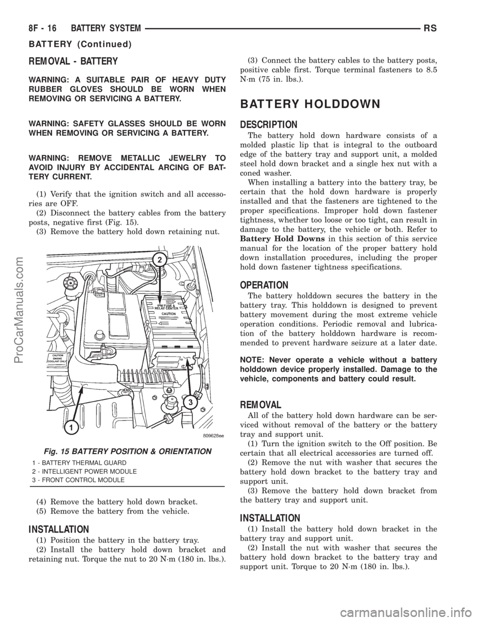
(2) Disconnect the battery cables from the battery
posts, negative first (Fig. 15).
(3) Remove the battery hold down retaining nut.
(4) Remove the battery hold down bracket.
(5) Remove the battery from the vehicle.
INSTALLATION
(1) Position the battery in the battery tray.
(2) Install the battery hold down bracket and
retaining nut. Torque the nut to 20 N´m (180 in. lbs.).(3) Connect the battery cables to the battery posts,
positive cable first. Torque terminal fasteners to 8.5
N´m (75 in. lbs.).
BATTERY HOLDDOWN
DESCRIPTION
The battery hold down hardware consists of a
molded plastic lip that is integral to the outboard
edge of the battery tray and support unit, a molded
steel hold down bracket and a single hex nut with a
coned washer.
When installing a battery into the battery tray, be
certain that the hold down hardware is properly
installed and that the fasteners are tightened to the
proper specifications. Improper hold down fastener
tightness, whether too loose or too tight, can result in
damage to the battery, the vehicle or both. Refer to
Battery Hold Downsin this section of this service
manual for the location of the proper battery hold
down installation procedures, including the proper
hold down fastener tightness specifications.
OPERATION
The battery holddown secures the battery in the
battery tray. This holddown is designed to prevent
battery movement during the most extreme vehicle
operation conditions. Periodic removal and lubrica-
tion of the battery holddown hardware is recom-
mended to prevent hardware seizure at a later date.
NOTE: Never operate a vehicle without a battery
holddown device properly installed. Damage to the
vehicle, components and battery could result.
REMOVAL
All of the battery hold down hardware can be ser-
viced without removal of the battery or the battery
tray and support unit.
(1) Turn the ignition switch to the Off position. Be
certain that all electrical accessories are turned off.
(2) Remove the nut with washer that secures the
battery hold down bracket to the battery tray and
support unit.
(3) Remove the battery hold down bracket from
the battery tray and support unit.
INSTALLATION
(1) Install the battery hold down bracket in the
battery tray and support unit.
(2) Install the nut with washer that secures the
battery hold down bracket to the battery tray and
support unit. Torque to 20 N´m (180 in. lbs.).
Fig. 15 BATTERY POSITION & ORIENTATION
1 - BATTERY THERMAL GUARD
2 - INTELLIGENT POWER MODULE
3 - FRONT CONTROL MODULE
8F - 16 BATTERY SYSTEMRS
BATTERY (Continued)
ProCarManuals.com