2001 DODGE TOWN AND COUNTRY remove seats
[x] Cancel search: remove seatsPage 73 of 2321
(7) Install the jounce bumper on the strut shaft
(Fig. 39). The jounce bumper is to be installed with
the small end pointing downward.
(8) Install the dust shield on the strut. Collapse
and stretch the dust shield down over the top of the
jounce bumper until the dust shield snaps into the
slot on the jounce bumper. The jounce bumper will be
at the top of the inner dust boot. Return the dust
shield to its fully extended length.
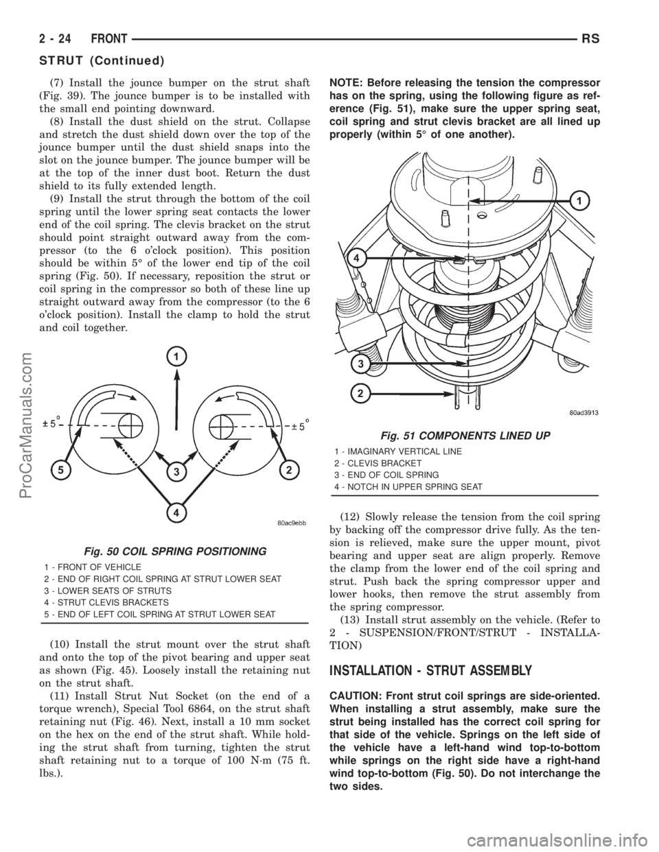
(9) Install the strut through the bottom of the coil
spring until the lower spring seat contacts the lower
end of the coil spring. The clevis bracket on the strut
should point straight outward away from the com-
pressor (to the 6 o'clock position). This position
should be within 5É of the lower end tip of the coil
spring (Fig. 50). If necessary, reposition the strut or
coil spring in the compressor so both of these line up
straight outward away from the compressor (to the 6
o'clock position). Install the clamp to hold the strut
and coil together.
(10) Install the strut mount over the strut shaft
and onto the top of the pivot bearing and upper seat
as shown (Fig. 45). Loosely install the retaining nut
on the strut shaft.
(11) Install Strut Nut Socket (on the end of a
torque wrench), Special Tool 6864, on the strut shaft
retaining nut (Fig. 46). Next, install a 10 mm socket
on the hex on the end of the strut shaft. While hold-
ing the strut shaft from turning, tighten the strut
shaft retaining nut to a torque of 100 N´m (75 ft.
lbs.).NOTE: Before releasing the tension the compressor
has on the spring, using the following figure as ref-
erence (Fig. 51), make sure the upper spring seat,
coil spring and strut clevis bracket are all lined up
properly (within 5É of one another).
(12) Slowly release the tension from the coil spring
by backing off the compressor drive fully. As the ten-
sion is relieved, make sure the upper mount, pivot
bearing and upper seat are align properly. Remove
the clamp from the lower end of the coil spring and
strut. Push back the spring compressor upper and
lower hooks, then remove the strut assembly from
the spring compressor.
(13) Install strut assembly on the vehicle. (Refer to
2 - SUSPENSION/FRONT/STRUT - INSTALLA-
TION)
INSTALLATION - STRUT ASSEMBLY
CAUTION: Front strut coil springs are side-oriented.
When installing a strut assembly, make sure the
strut being installed has the correct coil spring for
that side of the vehicle. Springs on the left side of
the vehicle have a left-hand wind top-to-bottom
while springs on the right side have a right-hand
wind top-to-bottom (Fig. 50). Do not interchange the
two sides.
Fig. 50 COIL SPRING POSITIONING
1 - FRONT OF VEHICLE
2 - END OF RIGHT COIL SPRING AT STRUT LOWER SEAT
3 - LOWER SEATS OF STRUTS
4 - STRUT CLEVIS BRACKETS
5 - END OF LEFT COIL SPRING AT STRUT LOWER SEAT
Fig. 51 COMPONENTS LINED UP
1 - IMAGINARY VERTICAL LINE
2 - CLEVIS BRACKET
3 - END OF COIL SPRING
4 - NOTCH IN UPPER SPRING SEAT
2 - 24 FRONTRS
STRUT (Continued)
ProCarManuals.com
Page 193 of 2321
For information on master cylinder application,
bore and type, view the following table:
BRAKE SYSTEMMASTER CYLINDER
BORE/TYPE
Disc/Drum - ABS23.8 mm Conventional
Compensating Port
Disc/Drum - Non-ABS23.8 mm Conventional
Compensating Port
Disc/Disc - ABS25.4 mm (1-1/16 in.)
Conventional
Compensating Port
Disc/Disc ABS With
Traction Control25.4 mm (1-1/16 in.) Dual
Center Port
CAUTION: When replacing a master cylinder, be
sure to use the correct master cylinder for the type
of brake system the vehicle is equipped with.
The body of the master cylinder is an anodized alu-
minum casting. It has a machined bore to accept the
master cylinder pistons and threaded ports with
seats for the hydraulic brake line connections.
The brake fluid reservoir is mounted on the top of
the master cylinder. It is made of a see-through
polypropylene type plastic for easy fluid level view-
ing. A brake fluid level switch is attached to the
brake fluid reservoir.
The master cylinder is not a repairable component
and must be replaced if diagnosed to be functioning
improperly. The brake fluid reservoir and brake fluid
level switch can be replaced separately.
CAUTION: Do not hone the bore of the cylinder as
this will remove the anodized surface from the bore.
OPERATION
When the brake pedal is depressed, the master cyl-
inder primary and secondary pistons apply brake
pressure through the chassis tubes to the brakes at
each tire and wheel assembly.
The master cylinder primary outlet port supplies
hydraulic pressure to the right front and left rear
brakes. The secondary outlet port supplies hydraulic
pressure to the left front and right rear brakes.
STANDARD PROCEDURE - MASTER CYLINDER
BLEEDING
CAUTION: When clamping master cylinder in vise,
only clamp master cylinder by its mounting flange,
do not clamp on primary piston, seal or body of
master cylinder.(1) Clamp the master cylinder in a vise using only
the mounting flange.
NOTE: Two different size bleeding tubes need to be
used depending on which type of master cylinder
the vehicle is equipped with. Vehicles equipped
with traction control have different size brake tubes
and nuts at the master cylinder than the non-trac-
tion control equipped vehicles. Be sure the correct
size bleeding tubes are used when bleeding the
master cylinder.
(2) Thread Bleeding Tubes, Special Tool 8358, for a
non-traction control master cylinder or Special Tool
8129 for a traction control master cylinder into mas-
ter cylinder primary and secondary ports. Position
outlet ends of bleeding tubes in reservoir with the
outlets below surface of brake fluid when reservoir is
filled to its proper level.
(3) Fill brake fluid reservoir with Mopartbrake
fluid or equivalent conforming to DOT 3 (DOT 4 and
DOT 4+ are acceptable) specifications.
(4) Using a wooden dowel, depress push rod slowly,
and then allow pistons to return to released position.
Repeat several times until all air bubbles are
expelled from master cylinder.
(5) Remove bleeding tubes from master cylinder
outlet ports, and then plug outlet ports and install
fill cap on reservoir.
(6) Remove master cylinder from vise.
(7) Install the filler cap on master cylinder fluid
reservoir.
(8) Install master cylinder. (Refer to 5 - BRAKES -
BASE/HYDRAULIC/MECHANICAL/MASTER CYL-
INDER - INSTALLATION)
REMOVAL - MASTER CYLINDER
CAUTION: Vacuum in the power brake booster must
be pumped down (removed) before removing mas-
ter cylinder from power brake booster. This is nec-
essary to prevent the power brake booster from
sucking in any contamination as the master cylin-
der is removed. This can be done simply by pump-
ing the brake pedal, with the vehicle's engine not
running, until a firm feeling brake pedal is achieved.
(1) With engine not running, pump brake pedal
until a firm pedal is achieved (4-5 strokes).
(2) Disconnect negative battery terminal.
(3) Disconnect positive battery terminal.
(4) Remove battery shield.
(5) Remove nut and clamp securing battery to tray,
remove battery.
5 - 34 BRAKES - BASERS
MASTER CYLINDER (Continued)
ProCarManuals.com
Page 245 of 2321
ROTORS
SPECIFICATIONS
BRAKE ROTOR
NOTE: Use the following information on all 4 wheel
disc brake vehicles that are equipped with BR3
sales code.When refacing a rotor, the required TIR (Total
Indicator Reading) and thickness variation limits
MUST BE MAINTAINED. Extreme care in the oper-
ation of rotor turning equipment is required.
SPECIFICATIONS/LIMITS
Brake
RotorRotor ThicknessMinimum Rotor
ThicknessRotor
Thickness
VariationRotor Runout *Rotor Micro
Finish
Front27.9-28.1 mm
1.098 -1.106 in.26.5 mm
1.043 in0.010 mm
0.0004 in.0.030 mm
0.0012 in.15-80 RMS
Rear12.25-12.75 mm
0.482-0.502 in.11.25 mm
0.443 in.0.013 mm
0.0005 in.0.14 mm
0.0055 in.15-80 RMS
* TIR Total Indicator Reading (Measured On Vehicle)
PARKING BRAKE
DESCRIPTION
The parking brake system on this vehicle features
a hand-operated parking brake lever. The lever is
located between the two front seats and requires a
special front cable.
CABLES - PARKING BRAKE
REMOVAL - FRONT CABLE
(Refer to 5 - BRAKES - BASE/PARKING BRAKE/
LEVER - REMOVAL)
INSTALLATION - FRONT CABLE
(Refer to 5 - BRAKES - BASE/PARKING BRAKE/
LEVER - INSTALLATION)
LEVER - PARKING BRAKE
REMOVAL - PARKING BRAKE LEVER AND
FRONT CABLE
(1) Raise vehicle. (Refer to LUBRICATION &
MAINTENANCE/HOISTING - STANDARD PROCE-
DURE)
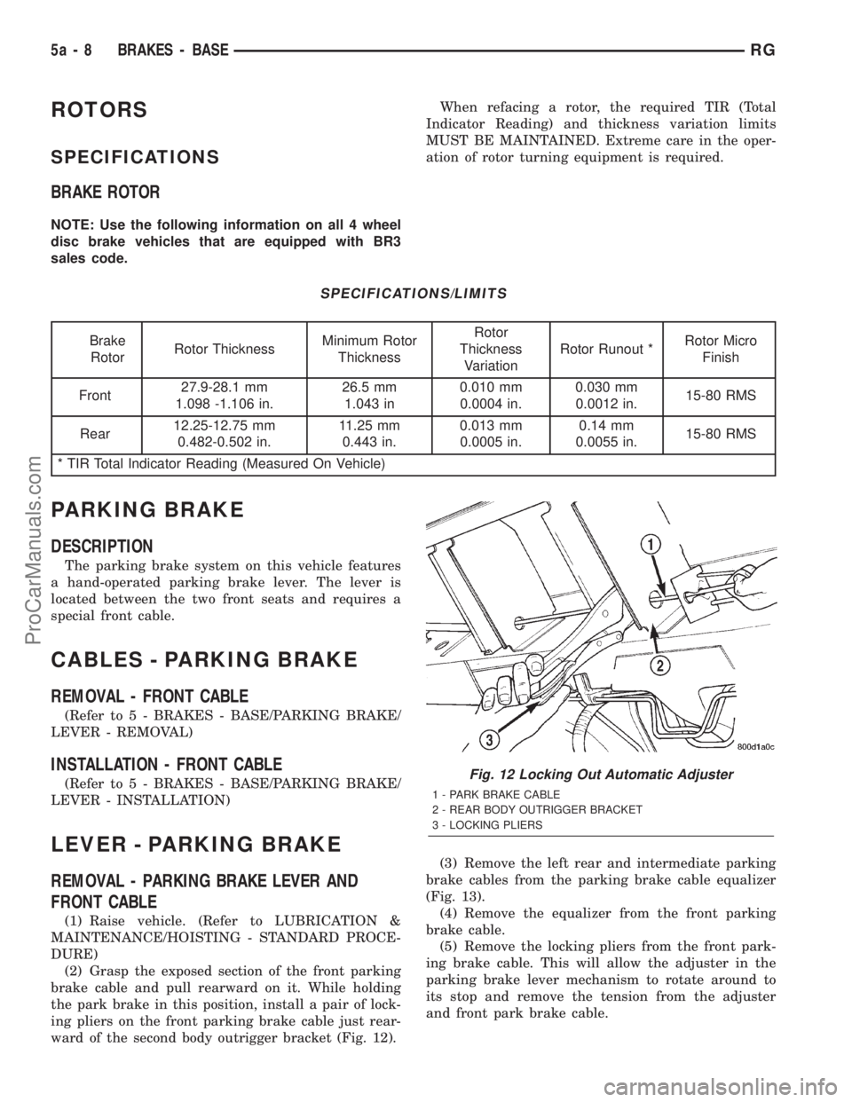
(2) Grasp the exposed section of the front parking
brake cable and pull rearward on it. While holding
the park brake in this position, install a pair of lock-
ing pliers on the front parking brake cable just rear-
ward of the second body outrigger bracket (Fig. 12).(3) Remove the left rear and intermediate parking
brake cables from the parking brake cable equalizer
(Fig. 13).
(4) Remove the equalizer from the front parking
brake cable.
(5) Remove the locking pliers from the front park-
ing brake cable. This will allow the adjuster in the
parking brake lever mechanism to rotate around to
its stop and remove the tension from the adjuster
and front park brake cable.
Fig. 12 Locking Out Automatic Adjuster
1 - PARK BRAKE CABLE
2 - REAR BODY OUTRIGGER BRACKET
3 - LOCKING PLIERS
5a - 8 BRAKES - BASERG
ProCarManuals.com
Page 554 of 2321
²UNLOCK: Pressing the UNLOCK button once
will unlock the driver's side doors and activate the
illuminated entry system and disarm Vehicle Theft
Security System, if equipped. Pressing the UNLOCK
button twice within five seconds will unlock all doors
and activate the illuminated entry system.
²LEFT SLIDING DOOR: Pressing the LEFT
SLIDING DOOR BUTTON opens/closes the left
power sliding door remotely.
²RIGHT SLIDING DOOR: Pressing the RIGHT
SLIDING DOOR BUTTON opens/closes the right
power sliding door remotely.
²LIFTGATE: Pressing the LIFTGATE BUTTON
opens/closes the liftgate remotely.
²PANIC: Pressing the PANIC button sounds the
horns at half second intervals, flashes the exterior
lamps, and turns ON the interior lamps. The panic
alarm will remain on for three minutes, or until the
PANIC button is actuated again or the ignition
switch is turned to the RUN position.
The Remote Keyless Entry Module is capable of
retaining the transmitter Vehicle Access Code(s)
(VAC) in its memory even after vehicle power has
been interrupted.
NOTE: Additional features available to the customer
are described in the Vehicle Owners Manual.
The RKE system activates the optional memory
seat and mirror system, if equipped. Two primary
key fob transmitters can be programmed to actuate
memory seat and mirror setting 1 or 2. Two addi-
tional key fob transmitters can be added, but they
will not be able to operate the memory seat and mir-
ror system (Refer to 8 - ELECTRICAL/POWER
SEATS - OPERATION) and (Refer to 8 - ELECTRI-
CAL/POWER MIRRORS - OPERATION).
DOOR LOCK MOTOR
DIAGNOSIS AND TESTING - DOOR LOCK
MOTOR
Verify battery condition before testing door lock
motor(s) (Refer to 8 - ELECTRICAL/BATTERY SYS-
TEM/BATTERY - DIAGNOSIS AND TESTING).
To determine which motor is faulty, check each
individual door for electrical lock and unlock or dis-
connect the motor connectors one at a time, while
operating the door lock switch. In the event that
none of the motors work, the problem may be caused
by a shorted motor or a bad switch. Disconnecting
the defective motor will allow the others to work.
To test an individual door lock motor, disconnect
the electrical connector from the motor. To lock the
door, connect a 12 volt power source to the positivepin of the lock motor and a ground wire to the other
pin. Refer to the appropriate wiring information. The
wiring information includes wiring diagrams, proper
wire and connector repair procedures, further details
on wire harness routing and retention, as well as
pin-out and location views for the various wire har-
ness connectors, splices and grounds. To unlock the
door reverse the wire connections at the motor pin
terminals. If these results are NOT obtained, replace
the motor.
DOOR LOCK SWITCH
DESCRIPTION
The Power Door Lock Switch is attached to the
door trim panel with two screws.
DIAGNOSIS AND TESTING - DOOR LOCK
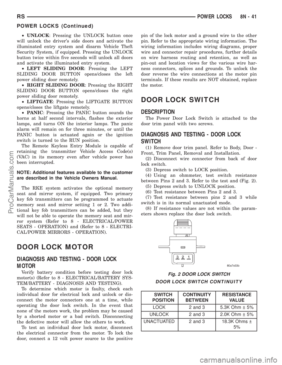
SWITCH
(1) Remove door trim panel. Refer to Body, Door -
Front, Trim Panel, Removal and Installation.
(2) Disconnect wire connector from back of door
lock switch.
(3) Depress switch to LOCK position.
(4) Using an ohmmeter, test switch resistance
between Pins 2 and 3. Refer to the test and (Fig. 2).
(5) Depress switch to UNLOCK position.
(6) Test resistance between Pins 2 and 3.
(7) Test resistance between pins 2 and 3 while
switch is in its normal unactuated mode.
(8) If resistance values are not within the param-
eters shown replace the door lock switch.
DOOR LOCK SWITCH CONTINUITY
SWITCH
POSITIONCONTINUITY
BETWEENRESISTANCE
VALUE
LOCK 2 and 3 5.3K Ohm 5%
UNLOCK 2 and 3 2.0K Ohm 5%
UNACTUATED 2 and 3 18.3K Ohms
5%
Fig. 2 DOOR LOCK SWITCH
RSPOWER LOCKS8N-41
POWER LOCKS (Continued)
ProCarManuals.com
Page 556 of 2321
REMOTE KEYLESS ENTRY
MODULE
DESCRIPTION
The RKE module is capable of retaining up to four
different Vehicle Access Codes.
OPERATION
Whenever the vehicle battery power is interrupted
the RKE Module will retain all vehicle access codes
in its memory. When replacing or adding a key fob
transmitter (maximum 4) a DRB IIItscan tool is
required to program the RKE Module to accept the
new Vehicle Access Code if a customer owned trans-
mitter is not available. Refer to Electrical, Remote
Keyless Entry Module, Standard Procedure - Pro-
gramming RKE Module or the Proper Body Diagnos-
tic Procedures manual.
DIAGNOSIS AND TESTING - REMOTE KEYLESS
ENTRY
Refer to the appropriate wiring information. The
wiring information includes wiring diagrams, proper
wire and connector repair procedures, further details
on wire harness routing and retention, as well as
pin-out and location views for the various wire har-
ness connectors, splices and grounds. Refer to the
proper Body Diagnostic Procedures Manual for test-
ing the Remote Keyless Entry system using a DRB
IIItscan tool. Also refer to other interrelated sys-
tems groups within this manual:
²Vehicle Theft Security System
²Power Seats
²Power Mirrors
STANDARD PROCEDURE - PROGRAMMING
RKE MODULE
(1) Using a functional key fob transmitter, unlock
the vehicle and disarm the Vehicle Theft Security
System.
(2) Insert ignition key into the ignition switch.
(3) Turn the ignition switch to RUN position with-
out starting engine.
(4) Using a functional key fob transmitter, press
and hold the UNLOCK button for a minimum five
seconds (maximum ten seconds).
(5) While still holding UNLOCK button, and
before ten seconds passes, press the PANIC button
and release both at the same time. A single chime
will sound to verify that the RKE module is set to
receive the new Vehicle Access Code(s).
(6) Within 30 seconds of the chime, press and
release the ªLOCKº and ªUNLOCKº buttons on the
transmitter at the same time. Then press any one of
the buttons. The BCM will sound an abbreviatedchime to acknowledge that the programming of the
transmitter has been completed and was successful.
(7) Repeat step 6 for all transmitters that will be
used with this vehicle (up to 4 total).
(8) Programming mode will last for 30 seconds. To
get out of programming mode sooner, turn the igni-
tion OFF. A single chime will sound to verify that the
RKE module will no longer accept additional Vehicle
Access Code(s).
(9) When Vehicle Access Code(s) programming is
complete, turn the ignition switch to the OFF posi-
tion and verify RKE system operation using each key
fob.
NOTE:
Only the two key fob transmitters that have been
programmed to the memory seat and mirror system
will operate it. If any key fob is replaced, the mem-
ory seat and mirror module will require program-
ming. (Refer to 8 - ELECTRICAL/POWER SEATS -
DIAGNOSIS AND TESTING).
REMOVAL
(1) Disconnect and isolate the battery negative
cable.
(2) Remove instrument panel top cover (Refer to
23 - BODY/INSTRUMENT PANEL/INSTRUMENT
PANEL TOP PAD - REMOVAL).
(3) Remove screws holding RKE module to instru-
ment panel.
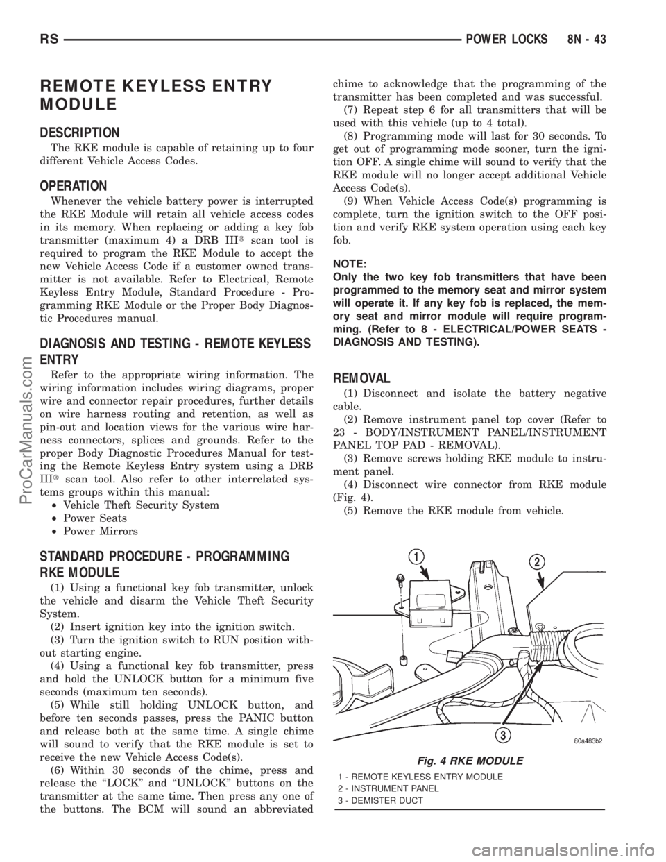
(4) Disconnect wire connector from RKE module
(Fig. 4).
(5) Remove the RKE module from vehicle.
Fig. 4 RKE MODULE
1 - REMOTE KEYLESS ENTRY MODULE
2 - INSTRUMENT PANEL
3 - DEMISTER DUCT
RSPOWER LOCKS8N-43
ProCarManuals.com
Page 565 of 2321

upon the second energizing is the amount the soft
stops have been reprogrammed.
Repeat this procedure for each direction of seat
movement (One at a time).
NOTE: Checking and resetting of the power mem-
ory seat soft stops will not affect the customer's
programmed positions.
DIAGNOSIS AND TESTING MEMORY SYSTEM
In order to obtain conclusive testing of the memory
system, the Programmable Communications Interface
(PCI) data bus network and all of the electronic mod-
ules that provide inputs to, or receive outputs from
the memory system components must be checked.
The most reliable, efficient, and accurate means to
diagnose the memory system requires the use of a
DRB IIItscan tool and the proper Diagnostic Proce-
dures manual. The DRB IIItscan tool can provide
confirmation that the PCI data bus is functional, that
all of the electronic modules are sending and receiv-
ing the proper messages on the PCI data bus, and
that the memory system is receiving the proper hard
wired inputs and relaying the proper hard wired out-
puts to perform its functions.
Following are diagnostic routines that are built
into the module which can be performed without the
use of a diagnostic scan tool. Refer to Wiring Dia-
grams for complete circuit schematic or connector
pin-out information.
DIAGNOSTIC MODE 1
Diagnostic Mode 1 clears soft limits and sets mem-
ory selector switches (1 and 2) to predetermined val-
ues.
ACTIVATION-Press and hold the S and 1 buttons
for 5 seconds to enter diagnostic mode 1. This mode
is exited at the completion of the mode 1 tasks or
upon grounding the DATA G87 circuit input to the
module.
Mode 1 will:
²Clear all soft limits to their default hard limit
values
²Load memory 1 with default settings corre-
sponding to horizontal rearward, front down, rear
down, and recliner rearward positions
²Load memory 2 with default settings corre-
sponding to horizontal forward, front up, rear up,
and recliner forward positions
DIAGNOSTIC MODE 2
Diagnostic mode 2 provides a way to determine if
the seat/mirror motors and position sensors are con-
nected properly.
ACTIVATION-Press and hold the S and 2 buttons
for 5 seconds to enter diagnostic mode 2. This modeis exited after 5 seconds of switch inactivity or upon
grounding the DATA G87 circuit input by moving the
transmission out of the PARK position.
Mode 2 will:
²Place the seat and mirror motors at their mid-
point
²When a single axis of seat or mirror motion is
requested by pressing a switch, the corresponding
motor is energized. This tests switch input and motor
output
DRIVER SEAT SWITCH
DESCRIPTION
Vehicles equipped with power seats utilize a eight-
way power seat switch. This eight-way power seat
switch features two knobs ganged together on the
outboard seat cushion side shield (Fig. 2).
The switch is secured to the back of the seat cush-
ion side shield with two screws. However, the control
knobs for the seat switch unit must be removed
before the seat switch can be removed from the side
shield.
The power seat switch cannot be repaired. If one
switch is damaged or faulty, the entire power seat
switch unit must be replaced.
OPERATION
The power seat tracks can be adjusted in eight dif-
ferent ways using the power seat switches. See the
owner's manual in the vehicle glove box for more
information on the power seat switch functions and
the seat adjusting procedures.
When a power seat switch control knob or knobs
are actuated, a battery feed and a ground path are
applied through the switch contacts to the power seat
track or recliner adjuster motor. The selected
adjuster motor operates to move the seat track or
recliner through its drive unit in the selected direc-
tion until the switch is released, or until the travel
Fig. 2 Power Seat Switch - Typical
8N - 52 POWER SEATSRS
POWER SEATS (Continued)
ProCarManuals.com
Page 566 of 2321
limit of the adjuster is reached. When the switch is
moved in the opposite direction, the battery feed and
ground path to the motor are reversed through the
switch contacts. This causes the adjuster motor to
run in the opposite direction.
No power seat switch should be held applied in any
direction after the adjuster has reached its travel
limit. The power seat adjuster motors each contain a
self-resetting circuit breaker to protect them from
overload. However, consecutive or frequent resetting
of the circuit breaker must not be allowed to con-
tinue, or the motor may be damaged.
DIAGNOSIS AND TESTING - DRIVER SEAT
SWITCH
(1) Remove switch, refer to Switch Removal and
Installation in this section.
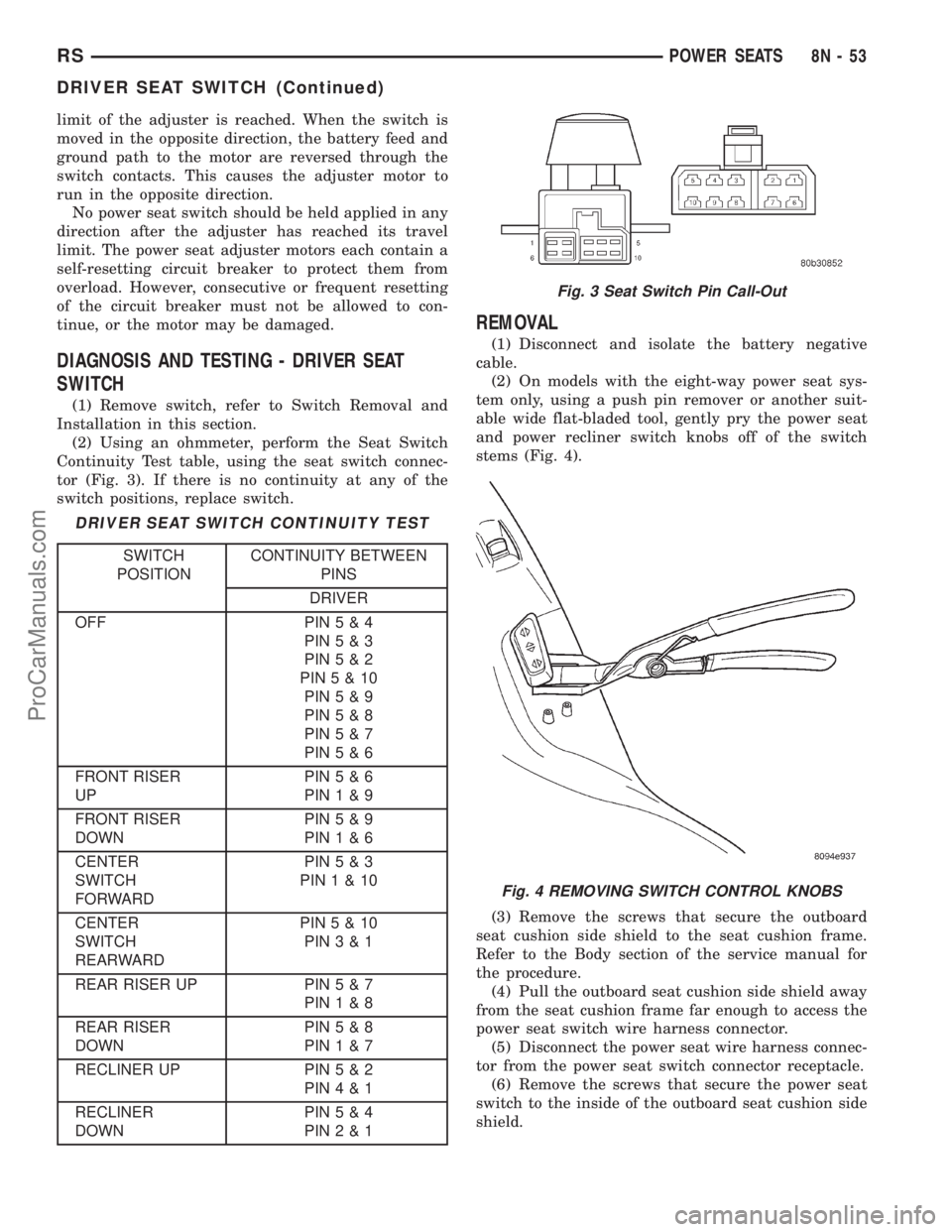
(2) Using an ohmmeter, perform the Seat Switch
Continuity Test table, using the seat switch connec-
tor (Fig. 3). If there is no continuity at any of the
switch positions, replace switch.
DRIVER SEAT SWITCH CONTINUITY TEST
SWITCH
POSITIONCONTINUITY BETWEEN
PINS
DRIVER
OFF PIN5&4
PIN5&3
PIN5&2
PIN5&10
PIN5&9
PIN5&8
PIN5&7
PIN5&6
FRONT RISER
UPPIN5&6
PIN1&9
FRONT RISER
DOWNPIN5&9
PIN1&6
CENTER
SWITCH
FORWARDPIN5&3
PIN1&10
CENTER
SWITCH
REARWARDPIN5&10
PIN3&1
REAR RISER UP PIN5&7
PIN1&8
REAR RISER
DOWNPIN5&8
PIN1&7
RECLINER UP PIN5&2
PIN4&1
RECLINER
DOWNPIN5&4
PIN2&1
REMOVAL
(1) Disconnect and isolate the battery negative
cable.
(2) On models with the eight-way power seat sys-
tem only, using a push pin remover or another suit-
able wide flat-bladed tool, gently pry the power seat
and power recliner switch knobs off of the switch
stems (Fig. 4).
(3) Remove the screws that secure the outboard
seat cushion side shield to the seat cushion frame.
Refer to the Body section of the service manual for
the procedure.
(4) Pull the outboard seat cushion side shield away
from the seat cushion frame far enough to access the
power seat switch wire harness connector.
(5) Disconnect the power seat wire harness connec-
tor from the power seat switch connector receptacle.
(6) Remove the screws that secure the power seat
switch to the inside of the outboard seat cushion side
shield.
Fig. 3 Seat Switch Pin Call-Out
Fig. 4 REMOVING SWITCH CONTROL KNOBS
RSPOWER SEATS8N-53
DRIVER SEAT SWITCH (Continued)
ProCarManuals.com
Page 567 of 2321
(7) Remove the power seat switch from the out-
board seat cushion side shield.
INSTALLATION
(1) Position the power seat switch onto the out-
board seat cushion side shield.
(2) Install and tighten the screws that secure the
power seat switch to the inside of the outboard seat
cushion side shield. Tighten the screws to 1.5 N´m
(14 in. lbs.).
(3) Reconnect the power seat wire harness connec-
tor to the power seat switch connector receptacle.
(4) Position the outboard seat cushion side shield
onto the seat cushion frame
(5) Install and tighten the screws that secure the
outboard seat cushion side shield to the seat cushion
frame. Tighten the screws to 1.5 N´m (14 in. lbs.).
(6) Reconnect the battery negative cable.
MEMORY SET SWITCH
DESCRIPTION
Vehicles equipped with the memory system have a
memory switch mounted to the driver side front door
trim panel. This switch is used to set and recall all of
the memory system settings for up to two drivers.
The memory switch is a resistor multiplexed unit
that is hard wired to the Body Control Module
(BCM). The BCM sends out the memory system set
and recall requests to the other electronic modules
over the Programmable Communications Interface
(PCI) data bus.
The memory switch cannot be adjusted or repaired
and, if faulty or damaged, it must be replaced. For
complete circuit diagrams, refer toWiring Dia-
grams.
OPERATION
The memory switch has three momentary switch
buttons labeled Set, 1 and 2. The Driver 1 and Driver
2 buttons are back-lit with Light-Emitting Diodes
(LED) for visibility, and are also color-coded to coin-
cide with the color-coded Driver 1 and Driver 2
Remote Keyless Entry (RKE) transmitters. The
Driver 1 memory switch button and RKE transmitter
are black, and the Driver 2 memory switch button
and RKE transmitter are gray. The memory switch
Set button also has an LED that will illuminate and
flash to indicate that the memory system is in the set
mode. This LED will automatically be extinguished
when a set request has been successfully completed.
See the owner's manual in the vehicle glove box for
more information on the features, use and operation
of the memory switch.
DIAGNOSIS AND TESTING - MEMORY SWITCH
For complete circuit diagrams, refer toWiring
Diagrams.
(1) Disconnect and isolate the battery negative
cable.
(2) Remove the driver side front door trim panel
switch bezel. Using a small thin bladed pry tool, gen-
tly pry the switch bezel away from the door trim
panel.
(3) Disconnect the memory switch wire harness
connector from the memory switch.
(4) Use an ohmmeter to test the resistances of the
memory switch in each switch position. See the Mem-
ory Switch Test chart. If OK, refer toMemory Sys-
temin the Diagnosis and Testing section of this
group. If not OK, replace the faulty memory switch.
MEMORY SWITCH TEST
MEMORY
SWITCH
POSITIONRESISTANCE
BETWEEN
PINSRESISTANCE
RANGE
(OHMS)
NEUTRAL 1&2 24560 1%
(24.56 k)
MEMORY 1 1&2 6830 1%
(6.83 k)
MEMORY 2 1&2 2090 1%
(2.09 k)
SET 1&2 4490 1%
(4.49 k)
REMOVAL
(1) Disconnect and isolate the battery negative
cable.
(2) Remove the front door trim panel switch bezel
from the driver side front door. Using a thin flat-
bladed pry tool, gently pry the switch bezel away
from the drivers door trim panel.
(3) Disconnect the memory switch wire harness
connector from the memory switch.
(4) Remove the two screws that secure the memory
switch to the back of the driver side front door trim
panel switch bezel.
(5) Remove the memory switch.
INSTALLATION
(1)Position the memory switch and install and
tighten the two screws that secure the memory switch
to the back of the driver side front door trim panel
switch bezel. Tighten the screws to 2.2 N´m (20 in. lbs.).
(2) Reconnect the memory switch wire harness
connector to the memory switch.
(3) Install the trim panel switch bezel onto the
driver side front door.
(4) Reconnect the battery negative cable.
8N - 54 POWER SEATSRS
DRIVER SEAT SWITCH (Continued)
ProCarManuals.com