2001 DODGE TOWN AND COUNTRY remove seats
[x] Cancel search: remove seatsPage 1914 of 2321
BODY
TABLE OF CONTENTS
page page
BODY
DESCRIPTION............................1
WARNING...............................2
DIAGNOSIS AND TESTING..................2
WATER LEAKS..........................2
WIND NOISE...........................3
STANDARD PROCEDURE...................4
PLASTIC BODY PANEL REPAIR.............4
HEAT STAKING.........................8
SPECIFICATIONS.........................9
SPECIAL TOOLS........................151DOOR - FRONT.........................152
DOORS - SLIDING.......................162
DECKLID/HATCH/LIFTGATE/TAILGATE.......180
EXTERIOR.............................184
HOOD................................199
INSTRUMENT PANEL....................202
INTERIOR.............................208
PAINT................................220
SEATS................................222
STATIONARY GLASS.....................243
WEATHERSTRIP/SEALS..................248
BODY
DESCRIPTION - LOCK CYLINDERS
Ignition, door, deck lid, and rear hatch lock cylin-
ders are all codable to the key. Lock barrels, tum-
blers, and tumbler springs are available to allow the
technician to change replacement locks cylinders to
match the customer's original key set. See the appro-
priate section in this manual for lock cylinder
removal. See the Moparž catalogue for part numbers
and lock coding procedures.
DESCRIPTION - VEHICLE IDENTIFICATION
Throughout this group, references to the
DaimlerChrysler Corporation vehicle family identifi-
cation code are used when describing a procedure
that is unique to that vehicle. Refer to Introduction
Group of this manual for detailed information on
vehicle identification. If a procedure is common to all
vehicles covered in this manual, no reference will be
made to a vehicle family code.
DESCRIPTION - PUSH-IN FASTENERS
DaimlerChrysler Corporation uses many different
types of push-in fasteners to secure the interior and
exterior trim to the body. Most of these fasteners can
be reused to assemble the trim during various repair
procedures. At times, a push-in fastener cannot be
removed without damaging the fastener or the com-
ponent it is holding. If it is not possible to remove a
fastener without damaging a component or body, cut
or break the fastener and use a new one when
installing the component. Never pry or pound on a
plastic or pressed-board trim component. Using a
suitable fork-type prying device, pry the fastener
from the retaining hole behind the component beingremoved. When installing, verify fastener alignment
with the retaining hole by hand. Push directly on or
over the fastener until it seats. Apply a low-force pull
to the panel to verify that it is secure.
When it is necessary to remove components to ser-
vice another, it should not be necessary to apply
excessive force or bend a component to remove it.
Before damaging a trim component, verify hidden
fasteners or captured edges holding the component in
place.
DESCRIPTION
PAINT
The original equipment finish is a multi-step pro-
cess that involves cleaning, electrodeposition (e-coat),
base coat, and clear coat steps. Additionally, selected
areas of the vehicle may be coated with an anti-chip
finish.
On most vehicles a two-stage paint application
(base coat/clear coat) is used. Color that is applied to
primer is called base coat. The clear coat protects the
base coat from ultraviolet light and provides a dura-
ble high-gloss finish.
STATIONARY GLASS
Windshields are made of two pieces of glass with a
plastic inner layer. Windshields and selected station-
ary glass are structural members of the vehicle. The
windshield glass is bonded to the windshield frame
with urethane adhesive.
Windshields and other stationary glass protect the
occupants from the effects of the elements. Wind-
shields are also used to retain some airbags in posi-
tion during deployment. Urethane bonded glass is
difficult to salvage during removal. The urethane
bonding is difficult to cut or clean from any surface.
RSBODY23-1
ProCarManuals.com
Page 1915 of 2321
Before removing the glass, check the availability of
replacement components.
SEATS
Seat modules are made up of a seat frame, seat
cushion, seat back cushion, a covering material, and
the electrical components used for power operation, if
equipped. Some seat systems also contain seat belt
components and supplemental restraint systems.
Seat assemblies transport the occupants in comfort
and safety. Seat assemblies also help position occu-
pants correctly in the event of airbag deployment.
Seat cushions, coverings, and electrical components
are serviceable. Refer to the appropriate group in
this manual.
EXTERIOR COMPONENTS
Exterior sheet metal components make up the
exterior of the vehicle. Some exterior metal systems
are welded assemblies, such as doors and hoods.
Some exterior trim items are made of composite.
The exterior is finished in various metal stampings
and composite moldings. These assemblies give the
vehicle a finished appearance and protect the occu-
pants from the elements. Some components are part
of the energy absorbing system used to protect the
occupants in collisions. The exterior sheet metal is
repairable and adjustable for fit and finish. Welded
and bonded component systems are adjustable as a
system. Trim components made of composite are
stamped with the type of material used.
DaimlerChrysler uses various fasteners to retain
trim items. At times, it is not possible to remove trim
items without damaging the fastener. If it is not pos-
sible to remove an item without damaging a compo-
nent, cut or break the fasteners and use new ones
when installing the component.
SAFETY PRECAUTIONS AND WARNINGS
WARNING:
EYE PROTECTION SHOULD BE USED WHEN SER-
VICING GLASS COMPONENTS. PERSONAL INJURY
CAN RESULT.
USE A OSHA APPROVED BREATHING FILTER
WHEN SPRAYING PAINT OR SOLVENTS IN A CON-
FINED AREA. PERSONAL INJURY CAN RESULT.
AVOID PROLONGED SKIN CONTACT WITH PETRO-
LEUM OR ALCOHOL BASED CLEANING SOLVENTS.
PERSONAL INJURY CAN RESULT.
DO NOT STAND UNDER A HOISTED VEHICLE THAT
IS NOT PROPERLY SUPPORTED ON SAFETY
STANDS. PERSONAL INJURY CAN RESULT.
CAUTION:
When holes must be drilled or punched in an innerbody panel, verify depth of space to the outer body
panel, electrical wiring, or other components. Dam-
age to vehicle can result.
Do not weld exterior panels unless combustible
material on the interior of vehicle is removed from
the repair area. Fire or hazardous conditions, can
result.
Always have a fire extinguisher ready for use when
welding.
Disconnect the negative battery cable clamp when
servicing electrical components that are live when
the ignition is OFF. Damage to electrical system can
result.
Do not use abrasive chemicals or compounds on
painted surfaces. Damage to finish can result.
Do not use harsh alkaline based cleaning solvents
on painted or upholstered surfaces. Damage to fin-
ish or color can result.
Do not hammer or pound on plastic trim panel
when servicing interior trim. Plastic panels can
break.
DIAGNOSIS AND TESTING - WATER LEAKS
Water leaks can be caused by poor sealing,
improper body component alignment, body seam
porosity, missing plugs, or blocked drain holes. Cen-
trifugal and gravitational force can cause water to
drip from a location away from the actual leak point,
making leak detection difficult. All body sealing
points should be water tight in normal wet-driving
conditions. Water flowing downward from the front of
the vehicle should not enter the passenger or luggage
compartment. Moving sealing surfaces will not
always seal water tight under all conditions. At
times, side glass or door seals will allow water to
enter the passenger compartment during high pres-
sure washing or hard driving rain (severe) condi-
tions. Overcompensating on door or glass
adjustments to stop a water leak that occurs under
severe conditions can cause premature seal wear and
excessive closing or latching effort. After completing
a repair, water test vehicle to verify leak has stopped
before returning vehicle to use.
VISUAL INSPECTION BEFORE WATER LEAK TESTS
Verify that floor and body plugs are in place, body
drains are clear, and body components are properly
aligned and sealed. If component alignment or seal-
ing is necessary, refer to the appropriate section of
this group for proper procedures.
WATER LEAK TESTS
WARNING: DO NOT USE ELECTRIC SHOP LIGHTS
OR TOOLS IN WATER TEST AREA. PERSONAL
INJURY CAN RESULT.
23 - 2 BODYRS
BODY (Continued)
ProCarManuals.com
Page 2124 of 2321
(2) Place B-pillar trim cover in position on vehicle.
(3) Engage hidden clips attaching trim cover to
B-pillar.
(4) Install screw attaching trim cover to B-pillar
inside bezel cavity.
(5) Install shoulder belt bezel into trim cover.
(6) Install height adjuster knob.
(7) Install shoulder belt turning loop onto height
adjuster. Tighten bolt to 39 N´m (29 ft. lbs.) torque.
(8) Place seat anchor in position on floor so web-
bing is pointed rearward and slightly outboard.
(9) Install bolt attaching lower seat belt anchor to
floor. Tighten seat belt bolt to 39 N´m (29 ft. lbs.)
torque.
CARPETS AND FLOOR MATS
REMOVAL
(1) Remove front seats. (Refer to 23 - BODY/
SEATS/SEAT - REMOVAL).
(2) Remove front center console.
(3) Remove the remaining seats. Refer to the Own-
er's Manual for the proper procedures.
(4) Remove front cowl panels and sill plates.
(5) Remove sliding door sill plates. (Refer to 23 -
BODY/INTERIOR/SLIDING DOOR SILL PLATE -
REMOVAL).
(6) Remove the cargo organizer, if equipped.
(7) Remove liftgate scuff plate. (Refer to 23 -
BODY/INTERIOR/LIFTGATE SCUFF PLATE -
REMOVAL).
(8) Remove lower B-pillar trim covers.
(9) Remove D-pillar trim covers.
(10) Remove Quarter trim panels.
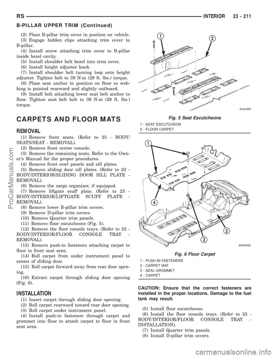
(11) Remove floor escutcheons (Fig. 5).
(12) Remove the floor console trays. (Refer to 23 -
BODY/INTERIOR/FLOOR CONSOLE TRAY -
REMOVAL).
(13) Remove push-in fasteners attaching carpet to
floor in front seat area.
(14) Roll carpet from under instrument panel to
center of sliding door.
(15) Roll carpet forward away from rear door open-
ing.
(16) Extract carpet through sliding door opening
(Fig. 6).
INSTALLATION
(1) Insert carpet through sliding door opening.
(2) Roll carpet rearward toward rear door opening.
(3) Roll carpet under instrument panel.
(4) Install push-in fasteners through carpet and
grommet into floor to attach carpet to floor in front
seat area.CAUTION: Ensure that the correct fasteners are
installed in the proper locations. Damage to the fuel
tank may result.
(5) Install floor escutcheons.
(6) Install the floor console trays. (Refer to 23 -
BODY/INTERIOR/FLOOR CONSOLE TRAY -
INSTALLATION).
(7) Install Quarter trim panels.
(8) Install D-pillar trim covers.
Fig. 5 Seat Escutcheons
1 - SEAT ESCUTCHEON
2 - FLOOR CARPET
Fig. 6 Floor Carpet
1 - PUSH-IN FASTENERS
2 - CARPET MAT
3 - SEAL GROMMET
4 - CARPET
RSINTERIOR23 - 211
B-PILLAR UPPER TRIM (Continued)
ProCarManuals.com
Page 2125 of 2321
(9) Install lower B-pillar trim covers.
(10) Install rear door sill plate.
(11) Install sliding door sill plates. (Refer to 23 -
BODY/INTERIOR/SLIDING DOOR SILL PLATE -
INSTALLATION).
(12) Install front cowl panels and sill plates.
(13) Install the passenger seats. Refer to the Own-
er's Manual for proper procedures.
(14) Install front center console.
(15) Install front seats. (Refer to 23 - BODY/
SEATS/SEAT - INSTALLATION).
COWL TRIM
REMOVAL
(1) Remove door sill plate.
(2) Disengage hidden clips holding cowl trim to
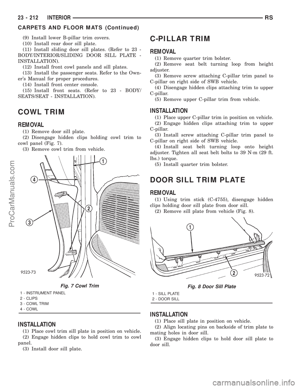
cowl panel (Fig. 7).
(3) Remove cowl trim from vehicle.
INSTALLATION
(1) Place cowl trim sill plate in position on vehicle.
(2) Engage hidden clips to hold cowl trim to cowl
panel.
(3) Install door sill plate.
C-PILLAR TRIM
REMOVAL
(1) Remove quarter trim bolster.
(2) Remove seat belt turning loop from height
adjuster.
(3) Remove screw attaching C-pillar trim panel to
C-pillar on right side of SWB vehicle.
(4) Disengage hidden clips attaching trim to upper
C-pillar.
(5) Remove upper C-pillar trim from vehicle.
INSTALLATION
(1) Place upper C-pillar trim in position on vehicle.
(2) Engage hidden clips attaching trim to upper
C-pillar.
(3) Install screw attaching C-pillar trim panel to
C-pillar on right side of SWB vehicle.
(4) Install seat belt turning loop onto height
adjuster. Tighten all seat belt bolts to 39 N´m (29 ft.
lbs.) torque.
(5) Install quarter trim bolster.
DOOR SILL TRIM PLATE
REMOVAL
(1) Using trim stick (C-4755), disengage hidden
clips holding door sill plate from door sill.
(2) Remove sill plate from vehicle (Fig. 8).
INSTALLATION
(1) Place sill plate in position on vehicle.
(2) Align locating pins on backside of trim plate to
mating holes in door sill.
(3) Engage hidden clips to hold door sill plate to
door sill.
Fig. 7 Cowl Trim
1 - INSTRUMENT PANEL
2 - CLIPS
3 - COWL TRIM
4 - COWL
Fig. 8 Door Sill Plate
1 - SILL PLATE
2 - DOOR SILL
23 - 212 INTERIORRS
CARPETS AND FLOOR MATS (Continued)
ProCarManuals.com
Page 2136 of 2321
BENCH SEAT BACK COVER
REMOVAL.............................240
INSTALLATION..........................240
BENCH SEAT TRACK
REMOVAL.............................240
INSTALLATION..........................240
PLASTIC GROCERY BAG RETAINER
REMOVAL.............................241
INSTALLATION..........................241
UNDER SEAT STORAGE BIN
REMOVAL.............................241INSTALLATION..........................241
UNDER SEAT STORAGE BIN GUIDE
REMOVAL.............................242
INSTALLATION..........................242
UNDER SEAT STORAGE BIN LOCK/LATCH
REMOVAL.............................242
INSTALLATION..........................242
LUMBAR SUPPORT
REMOVAL.............................242
INSTALLATION..........................242
CHILD SEAT MODULE
REMOVAL
(1) Close child restraint seat.
(2) Remove seat back cover.
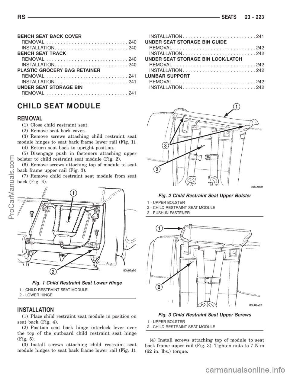
(3) Remove screws attaching child restraint seat
module hinges to seat back frame lower rail (Fig. 1).
(4) Return seat back to upright position.
(5) Disengage push in fasteners attaching upper
bolster to child restraint seat module (Fig. 2).
(6) Remove screws attaching top of module to seat
back frame upper rail (Fig. 3).
(7) Remove child restraint seat module from seat
back (Fig. 4).
INSTALLATION
(1) Place child restraint seat module in position on
seat back (Fig. 4).
(2) Position seat back hinge interlock lever over
the top of the outboard child restraint seat hinge
(Fig. 5).
(3) Install screws attaching child restraint seat
module hinges to seat back frame lower rail (Fig. 1).(4) Install screws attaching top of module to seat
back frame upper rail (Fig. 3). Tighten nuts to 7 N´m
(62 in. lbs.) torque.
Fig. 1 Child Restraint Seat Lower Hinge
1 - CHILD RESTRAINT SEAT MODULE
2 - LOWER HINGE
Fig. 2 Child Restraint Seat Upper Bolster
1 - UPPER BOLSTER
2 - CHILD RESTRAINT SEAT MODULE
3 - PUSH-IN FASTENER
Fig. 3 Child Restraint Seat Upper Screws
1 - UPPER BOLSTER
2 - CHILD RESTRAINT SEAT MODULE
RSSEATS23 - 223
ProCarManuals.com
Page 2137 of 2321
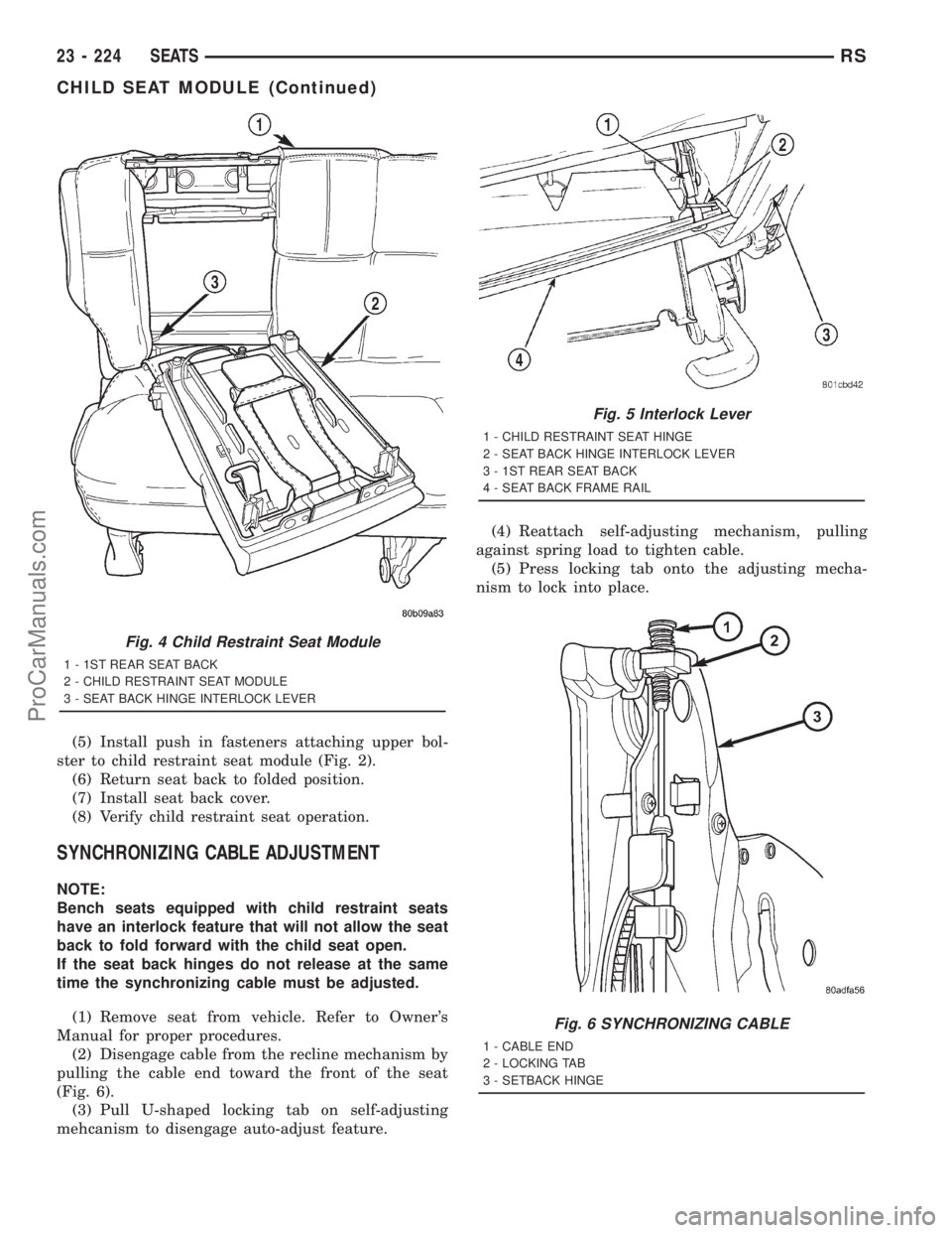
(5) Install push in fasteners attaching upper bol-
ster to child restraint seat module (Fig. 2).
(6) Return seat back to folded position.
(7) Install seat back cover.
(8) Verify child restraint seat operation.
SYNCHRONIZING CABLE ADJUSTMENT
NOTE:
Bench seats equipped with child restraint seats
have an interlock feature that will not allow the seat
back to fold forward with the child seat open.
If the seat back hinges do not release at the same
time the synchronizing cable must be adjusted.
(1) Remove seat from vehicle. Refer to Owner's
Manual for proper procedures.
(2) Disengage cable from the recline mechanism by
pulling the cable end toward the front of the seat
(Fig. 6).
(3) Pull U-shaped locking tab on self-adjusting
mehcanism to disengage auto-adjust feature.(4) Reattach self-adjusting mechanism, pulling
against spring load to tighten cable.
(5) Press locking tab onto the adjusting mecha-
nism to lock into place.
Fig. 4 Child Restraint Seat Module
1 - 1ST REAR SEAT BACK
2 - CHILD RESTRAINT SEAT MODULE
3 - SEAT BACK HINGE INTERLOCK LEVER
Fig. 5 Interlock Lever
1 - CHILD RESTRAINT SEAT HINGE
2 - SEAT BACK HINGE INTERLOCK LEVER
3 - 1ST REAR SEAT BACK
4 - SEAT BACK FRAME RAIL
Fig. 6 SYNCHRONIZING CABLE
1 - CABLE END
2 - LOCKING TAB
3 - SETBACK HINGE
23 - 224 SEATSRS
CHILD SEAT MODULE (Continued)
ProCarManuals.com
Page 2138 of 2321
QUAD CHILD SEAT
REMOVAL
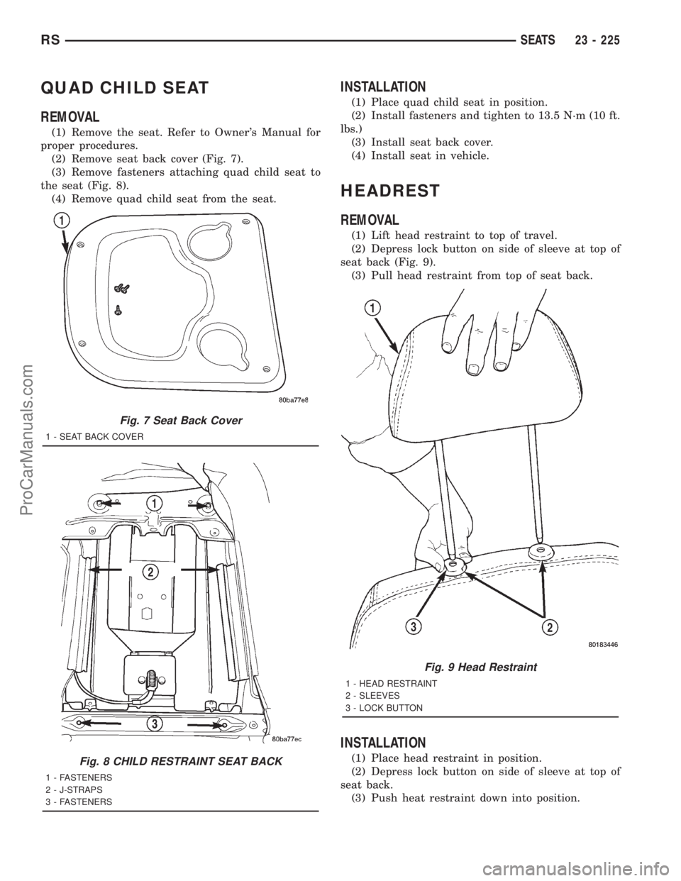
(1) Remove the seat. Refer to Owner's Manual for
proper procedures.
(2) Remove seat back cover (Fig. 7).
(3) Remove fasteners attaching quad child seat to
the seat (Fig. 8).
(4) Remove quad child seat from the seat.
INSTALLATION
(1) Place quad child seat in position.
(2) Install fasteners and tighten to 13.5 N´m (10 ft.
lbs.)
(3) Install seat back cover.
(4) Install seat in vehicle.
HEADREST
REMOVAL
(1) Lift head restraint to top of travel.
(2) Depress lock button on side of sleeve at top of
seat back (Fig. 9).
(3) Pull head restraint from top of seat back.
INSTALLATION
(1) Place head restraint in position.
(2) Depress lock button on side of sleeve at top of
seat back.
(3) Push heat restraint down into position.
Fig. 7 Seat Back Cover
1 - SEAT BACK COVER
Fig. 8 CHILD RESTRAINT SEAT BACK
1 - FASTENERS
2 - J-STRAPS
3 - FASTENERS
Fig. 9 Head Restraint
1 - HEAD RESTRAINT
2 - SLEEVES
3 - LOCK BUTTON
RSSEATS23 - 225
ProCarManuals.com
Page 2139 of 2321
HEADREST SLEEVE
REMOVAL
(1) Remove head rest.
(2) Disengage closure attaching bottom of trim
cover together.
(3) Reach under trim cover through opening at
bottom of seat back.
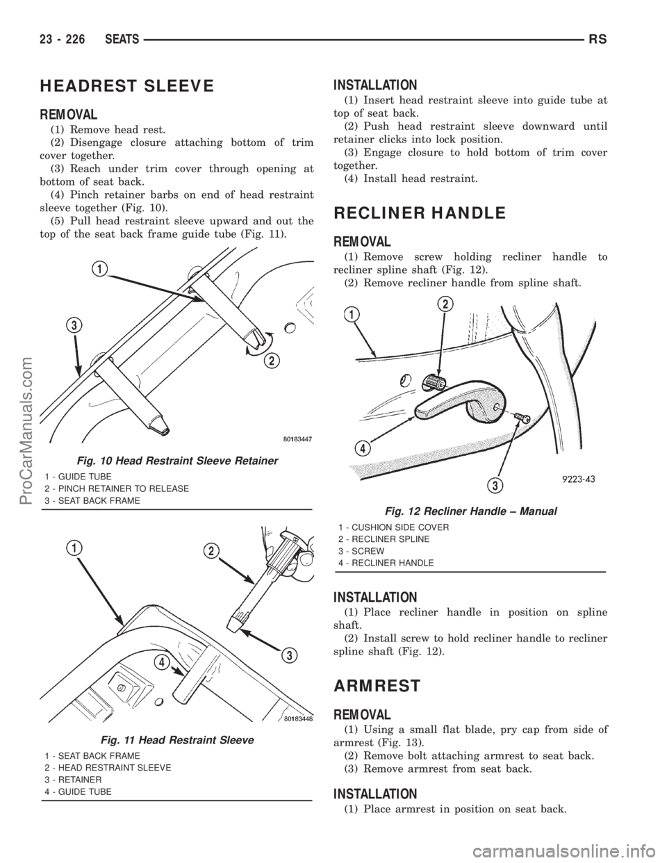
(4) Pinch retainer barbs on end of head restraint
sleeve together (Fig. 10).
(5) Pull head restraint sleeve upward and out the
top of the seat back frame guide tube (Fig. 11).
INSTALLATION
(1) Insert head restraint sleeve into guide tube at
top of seat back.
(2) Push head restraint sleeve downward until
retainer clicks into lock position.
(3) Engage closure to hold bottom of trim cover
together.
(4) Install head restraint.
RECLINER HANDLE
REMOVAL
(1) Remove screw holding recliner handle to
recliner spline shaft (Fig. 12).
(2) Remove recliner handle from spline shaft.
INSTALLATION
(1) Place recliner handle in position on spline
shaft.
(2) Install screw to hold recliner handle to recliner
spline shaft (Fig. 12).
ARMREST
REMOVAL
(1) Using a small flat blade, pry cap from side of
armrest (Fig. 13).
(2) Remove bolt attaching armrest to seat back.
(3) Remove armrest from seat back.
INSTALLATION
(1) Place armrest in position on seat back.
Fig. 10 Head Restraint Sleeve Retainer
1 - GUIDE TUBE
2 - PINCH RETAINER TO RELEASE
3 - SEAT BACK FRAME
Fig. 11 Head Restraint Sleeve
1 - SEAT BACK FRAME
2 - HEAD RESTRAINT SLEEVE
3 - RETAINER
4 - GUIDE TUBE
Fig. 12 Recliner Handle ± Manual
1 - CUSHION SIDE COVER
2 - RECLINER SPLINE
3 - SCREW
4 - RECLINER HANDLE
23 - 226 SEATSRS
ProCarManuals.com