2001 DODGE TOWN AND COUNTRY remove seats
[x] Cancel search: remove seatsPage 2140 of 2321
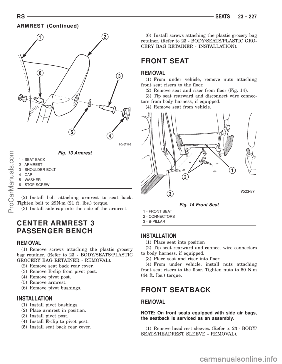
(2) Install bolt attaching armrest to seat back.
Tighten bolt to 29N´m (21 ft. lbs.) torque.
(3) Install side cap into the side of the armrest.
CENTER ARMREST 3
PASSENGER BENCH
REMOVAL
(1) Remove screws attaching the plastic grocery
bag retainer. (Refer to 23 - BODY/SEATS/PLASTIC
GROCERY BAG RETAINER - REMOVAL).
(2) Remove seat back rear cover.
(3) Remove E-clip from pivot post.
(4) Remove pivot post.
(5) Remove armrest.
(6) Remove pivot bushings.
INSTALLATION
(1) Install pivot bushings.
(2) Place armrest in position.
(3) Install pivot post.
(4) Install E-clip to pivot post.
(5) Install seat back rear cover.(6) Install screws attaching the plastic grocery bag
retainer. (Refer to 23 - BODY/SEATS/PLASTIC GRO-
CERY BAG RETAINER - INSTALLATION).
FRONT SEAT
REMOVAL
(1) From under vehicle, remove nuts attaching
front seat risers to the floor.
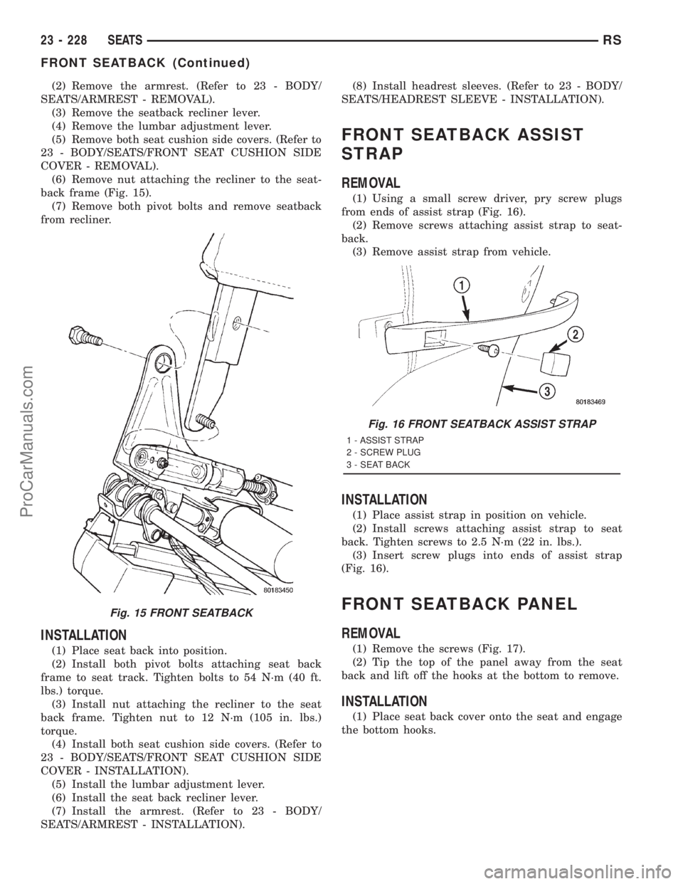
(2) Remove seat and riser from floor (Fig. 14).
(3) Tip seat rearward and disconnect wire connec-
tors from body harness, if equipped.
(4) Remove seat from vehicle.
INSTALLATION
(1) Place seat into position
(2) Tip seat rearward and connect wire connectors
to body harness, if equipped.
(3) Place seat and riser into floor.
(4) From under vehicle, install nuts attaching
front seat risers to the floor. Tighten nuts to 60 N´m
(44 ft. lbs.) torque.
FRONT SEATBACK
REMOVAL
NOTE: On front seats equipped with side air bags,
the seatback is serviced as an assembly.
(1) Remove head rest sleeves. (Refer to 23 - BODY/
SEATS/HEADREST SLEEVE - REMOVAL).
Fig. 13 Armrest
1 - SEAT BACK
2 - ARMREST
3 - SHOULDER BOLT
4 - CAP
5 - WASHER
6 - STOP SCREW
Fig. 14 Front Seat
1 - FRONT SEAT
2 - CONNECTORS
3 - B-PILLAR
RSSEATS23 - 227
ARMREST (Continued)
ProCarManuals.com
Page 2141 of 2321
(2) Remove the armrest. (Refer to 23 - BODY/
SEATS/ARMREST - REMOVAL).
(3) Remove the seatback recliner lever.
(4) Remove the lumbar adjustment lever.
(5) Remove both seat cushion side covers. (Refer to
23 - BODY/SEATS/FRONT SEAT CUSHION SIDE
COVER - REMOVAL).
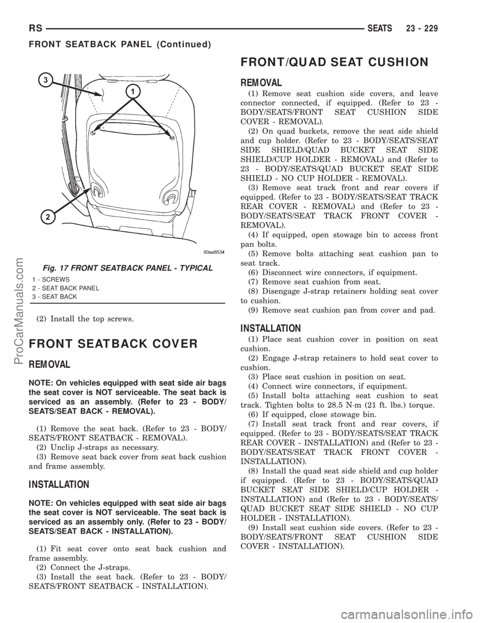
(6) Remove nut attaching the recliner to the seat-
back frame (Fig. 15).
(7) Remove both pivot bolts and remove seatback
from recliner.
INSTALLATION
(1) Place seat back into position.
(2) Install both pivot bolts attaching seat back
frame to seat track. Tighten bolts to 54 N´m (40 ft.
lbs.) torque.
(3) Install nut attaching the recliner to the seat
back frame. Tighten nut to 12 N´m (105 in. lbs.)
torque.
(4) Install both seat cushion side covers. (Refer to
23 - BODY/SEATS/FRONT SEAT CUSHION SIDE
COVER - INSTALLATION).
(5) Install the lumbar adjustment lever.
(6) Install the seat back recliner lever.
(7) Install the armrest. (Refer to 23 - BODY/
SEATS/ARMREST - INSTALLATION).(8) Install headrest sleeves. (Refer to 23 - BODY/
SEATS/HEADREST SLEEVE - INSTALLATION).
FRONT SEATBACK ASSIST
STRAP
REMOVAL
(1) Using a small screw driver, pry screw plugs
from ends of assist strap (Fig. 16).
(2) Remove screws attaching assist strap to seat-
back.
(3) Remove assist strap from vehicle.
INSTALLATION
(1) Place assist strap in position on vehicle.
(2) Install screws attaching assist strap to seat
back. Tighten screws to 2.5 N´m (22 in. lbs.).
(3) Insert screw plugs into ends of assist strap
(Fig. 16).
FRONT SEATBACK PANEL
REMOVAL
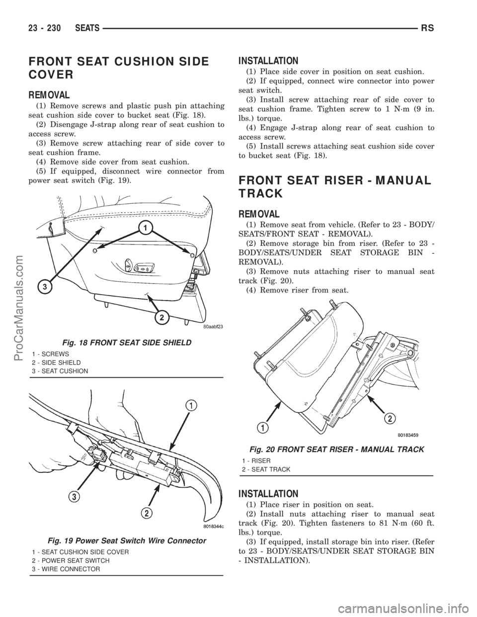
(1) Remove the screws (Fig. 17).
(2) Tip the top of the panel away from the seat
back and lift off the hooks at the bottom to remove.
INSTALLATION
(1) Place seat back cover onto the seat and engage
the bottom hooks.
Fig. 15 FRONT SEATBACK
Fig. 16 FRONT SEATBACK ASSIST STRAP
1 - ASSIST STRAP
2 - SCREW PLUG
3 - SEAT BACK
23 - 228 SEATSRS
FRONT SEATBACK (Continued)
ProCarManuals.com
Page 2142 of 2321
(2) Install the top screws.
FRONT SEATBACK COVER
REMOVAL
NOTE: On vehicles equipped with seat side air bags
the seat cover is NOT serviceable. The seat back is
serviced as an assembly. (Refer to 23 - BODY/
SEATS/SEAT BACK - REMOVAL).
(1) Remove the seat back. (Refer to 23 - BODY/
SEATS/FRONT SEATBACK - REMOVAL).
(2) Unclip J-straps as necessary.
(3) Remove seat back cover from seat back cushion
and frame assembly.
INSTALLATION
NOTE: On vehicles equipped with seat side air bags
the seat cover is NOT serviceable. The seat back is
serviced as an assembly only. (Refer to 23 - BODY/
SEATS/SEAT BACK - INSTALLATION).
(1) Fit seat cover onto seat back cushion and
frame assembly.
(2) Connect the J-straps.
(3) Install the seat back. (Refer to 23 - BODY/
SEATS/FRONT SEATBACK - INSTALLATION).
FRONT/QUAD SEAT CUSHION
REMOVAL
(1) Remove seat cushion side covers, and leave
connector connected, if equipped. (Refer to 23 -
BODY/SEATS/FRONT SEAT CUSHION SIDE
COVER - REMOVAL).
(2) On quad buckets, remove the seat side shield
and cup holder. (Refer to 23 - BODY/SEATS/SEAT
SIDE SHIELD/QUAD BUCKET SEAT SIDE
SHIELD/CUP HOLDER - REMOVAL) and (Refer to
23 - BODY/SEATS/QUAD BUCKET SEAT SIDE
SHIELD - NO CUP HOLDER - REMOVAL).
(3) Remove seat track front and rear covers if
equipped. (Refer to 23 - BODY/SEATS/SEAT TRACK
REAR COVER - REMOVAL) and (Refer to 23 -
BODY/SEATS/SEAT TRACK FRONT COVER -
REMOVAL).
(4) If equipped, open stowage bin to access front
pan bolts.
(5) Remove bolts attaching seat cushion pan to
seat track.
(6) Disconnect wire connectors, if equipment.
(7) Remove seat cushion from seat.
(8) Disengage J-strap retainers holding seat cover
to cushion.
(9) Remove seat cushion pan from cover and pad.
INSTALLATION
(1) Place seat cushion cover in position on seat
cushion.
(2) Engage J-strap retainers to hold seat cover to
cushion.
(3) Place seat cushion in position on seat.
(4) Connect wire connectors, if equipment.
(5) Install bolts attaching seat cushion to seat
track. Tighten bolts to 28.5 N´m (21 ft. lbs.) torque.
(6) If equipped, close stowage bin.
(7) Install seat track front and rear covers, if
equipped. (Refer to 23 - BODY/SEATS/SEAT TRACK
REAR COVER - INSTALLATION) and (Refer to 23 -
BODY/SEATS/SEAT TRACK FRONT COVER -
INSTALLATION).
(8) Install the quad seat side shield and cup holder
if equipped. (Refer to 23 - BODY/SEATS/QUAD
BUCKET SEAT SIDE SHIELD/CUP HOLDER -
INSTALLATION) and (Refer to 23 - BODY/SEATS/
QUAD BUCKET SEAT SIDE SHIELD - NO CUP
HOLDER - INSTALLATION).
(9) Install seat cushion side covers. (Refer to 23 -
BODY/SEATS/FRONT SEAT CUSHION SIDE
COVER - INSTALLATION).
Fig. 17 FRONT SEATBACK PANEL - TYPICAL
1 - SCREWS
2 - SEAT BACK PANEL
3 - SEAT BACK
RSSEATS23 - 229
FRONT SEATBACK PANEL (Continued)
ProCarManuals.com
Page 2143 of 2321
FRONT SEAT CUSHION SIDE
COVER
REMOVAL
(1) Remove screws and plastic push pin attaching
seat cushion side cover to bucket seat (Fig. 18).
(2) Disengage J-strap along rear of seat cushion to
access screw.
(3) Remove screw attaching rear of side cover to
seat cushion frame.
(4) Remove side cover from seat cushion.
(5) If equipped, disconnect wire connector from
power seat switch (Fig. 19).
INSTALLATION
(1) Place side cover in position on seat cushion.
(2) If equipped, connect wire connector into power
seat switch.
(3) Install screw attaching rear of side cover to
seat cushion frame. Tighten screw to 1 N´m (9 in.
lbs.) torque.
(4) Engage J-strap along rear of seat cushion to
access screw.
(5) Install screws attaching seat cushion side cover
to bucket seat (Fig. 18).
FRONT SEAT RISER - MANUAL
TRACK
REMOVAL
(1) Remove seat from vehicle. (Refer to 23 - BODY/
SEATS/FRONT SEAT - REMOVAL).
(2) Remove storage bin from riser. (Refer to 23 -
BODY/SEATS/UNDER SEAT STORAGE BIN -
REMOVAL).
(3) Remove nuts attaching riser to manual seat
track (Fig. 20).
(4) Remove riser from seat.
INSTALLATION
(1) Place riser in position on seat.
(2) Install nuts attaching riser to manual seat
track (Fig. 20). Tighten fasteners to 81 N´m (60 ft.
lbs.) torque.
(3) If equipped, install storage bin into riser. (Refer
to 23 - BODY/SEATS/UNDER SEAT STORAGE BIN
- INSTALLATION).
Fig. 18 FRONT SEAT SIDE SHIELD
1 - SCREWS
2 - SIDE SHIELD
3 - SEAT CUSHION
Fig. 19 Power Seat Switch Wire Connector
1 - SEAT CUSHION SIDE COVER
2 - POWER SEAT SWITCH
3 - WIRE CONNECTOR
Fig. 20 FRONT SEAT RISER - MANUAL TRACK
1 - RISER
2 - SEAT TRACK
23 - 230 SEATSRS
ProCarManuals.com
Page 2144 of 2321
(4) Install seat into vehicle. Tighten fasteners to
54 N´m (40 ft. lbs.) torque. (Refer to 23 - BODY/
SEATS/FRONT SEAT - INSTALLATION).
FRONT SEAT TRACK POWER
ADJUSTER
REMOVAL
The power seat track and motors are serviced as
an assembly.
(1) Remove seat from vehicle. (Refer to 23 - BODY/
SEATS/FRONT SEAT - REMOVAL).
(2) Remove seat cushion. (Refer to 23 - BODY/
SEATS/FRONT/QUAD SEAT CUSHION - REMOV-
AL).
(3) Remove nut attaching recliner to seat back
frame.
(4) Remove bolts attaching seat back frame to seat
track.
(5) Remove stud on seat back frame from recliner.
(6) Remove seat back.
(7) If power seat track is being replaced, transfer
power recliner, wire harness and trim covers to
replacement seat track.
INSTALLATION
The power seat track and motors are serviced as
an assembly.
(1) Install wire harness.
(2) Place seat back in position.
(3) Insert stud on seat back frame into recliner.
(4) Install bolts to hold seat back frame to seat
track.
(5) Install nut attaching recliner to seat back
frame.
(6) Install seat cushion. (Refer to 23 - BODY/
SEATS/FRONT/QUAD SEAT CUSHION - INSTAL-
LATION).
(7) Install seat in vehicle. Tighten fasteners to 60
N´m (44 ft. lbs.) torque. (Refer to 23 - BODY/SEATS/
FRONT SEAT - INSTALLATION).
FRONT SEAT TRACK MANUAL
ADJUSTER
REMOVAL
(1) Remove seat from vehicle. (Refer to 23 - BODY/
SEATS/FRONT SEAT - REMOVAL).
(2) Remove seat cushion. (Refer to 23 - BODY/
SEATS/FRONT/QUAD SEAT CUSHION - REMOV-
AL).(3) Remove riser. (Refer to 23 - BODY/SEATS/
FRONT SEAT RISER - MANUAL TRACK - REMOV-
AL).
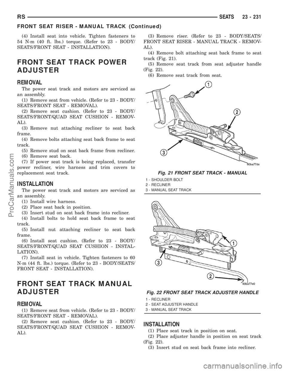
(4) Remove bolt attaching seat back frame to seat
track (Fig. 21).
(5) Remove seat track from seat adjuster handle
(Fig. 22).
(6) Remove seat track from seat.
INSTALLATION
(1) Place seat track in position on seat.
(2) Place adjuster handle in position on seat track
(Fig. 22).
(3) Insert stud on seat back frame into recliner.
Fig. 21 FRONT SEAT TRACK - MANUAL
1 - SHOULDER BOLT
2 - RECLINER
3 - MANUAL SEAT TRACK
Fig. 22 FRONT SEAT TRACK ADJUSTER HANDLE
1 - RECLINER
2 - SEAT ADJUSTER HANDLE
3 - MANUAL SEAT TRACK
RSSEATS23 - 231
FRONT SEAT RISER - MANUAL TRACK (Continued)
ProCarManuals.com
Page 2145 of 2321
(4) Install bolt attaching seat back frame to seat
track (Fig. 21).
(5) Install riser. (Refer to 23 - BODY/SEATS/
FRONT SEAT RISER - MANUAL TRACK - INSTAL-
LATION).
(6) Install seat cushion. (Refer to 23 - BODY/
SEATS/FRONT/QUAD SEAT CUSHION - INSTAL-
LATION).
(7) Install seat in vehicle. (Refer to 23 - BODY/
SEATS/FRONT SEAT - INSTALLATION).
FRONT SEAT TRACK - FRONT
COVER
REMOVAL
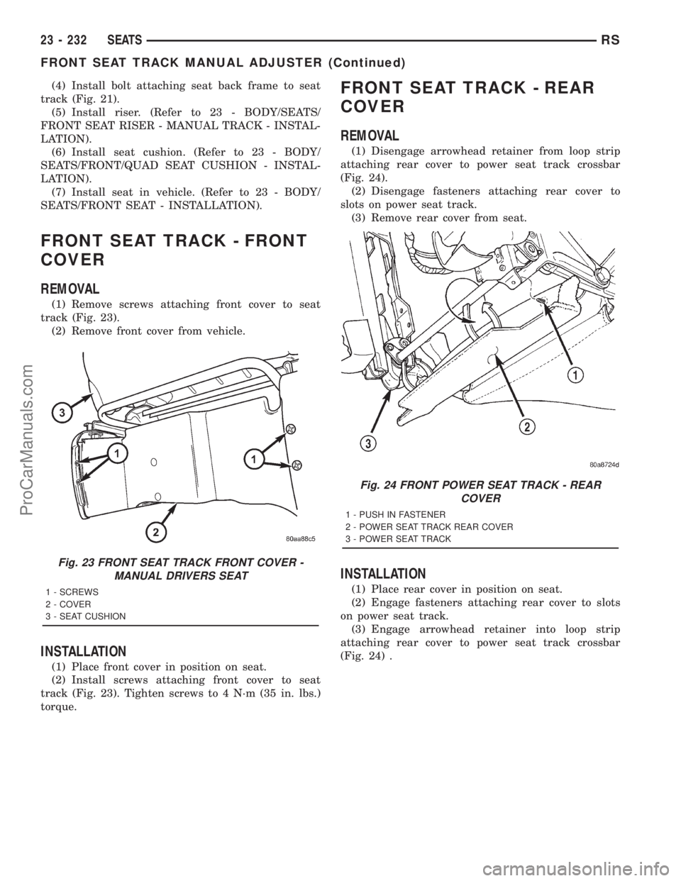
(1) Remove screws attaching front cover to seat
track (Fig. 23).
(2) Remove front cover from vehicle.
INSTALLATION
(1) Place front cover in position on seat.
(2) Install screws attaching front cover to seat
track (Fig. 23). Tighten screws to 4 N´m (35 in. lbs.)
torque.
FRONT SEAT TRACK - REAR
COVER
REMOVAL
(1) Disengage arrowhead retainer from loop strip
attaching rear cover to power seat track crossbar
(Fig. 24).
(2) Disengage fasteners attaching rear cover to
slots on power seat track.
(3) Remove rear cover from seat.
INSTALLATION
(1) Place rear cover in position on seat.
(2) Engage fasteners attaching rear cover to slots
on power seat track.
(3) Engage arrowhead retainer into loop strip
attaching rear cover to power seat track crossbar
(Fig. 24) .
Fig. 23 FRONT SEAT TRACK FRONT COVER -
MANUAL DRIVERS SEAT
1 - SCREWS
2 - COVER
3 - SEAT CUSHION
Fig. 24 FRONT POWER SEAT TRACK - REAR
COVER
1 - PUSH IN FASTENER
2 - POWER SEAT TRACK REAR COVER
3 - POWER SEAT TRACK
23 - 232 SEATSRS
FRONT SEAT TRACK MANUAL ADJUSTER (Continued)
ProCarManuals.com
Page 2146 of 2321
QUAD BUCKET SEAT SIDE
SHIELD/CUP HOLDER
REMOVAL
(1) Remove the seat from the vehicle. Refer to
Owner's Manual for proper procedures.
(2) Remove the two screws and remove the hinge
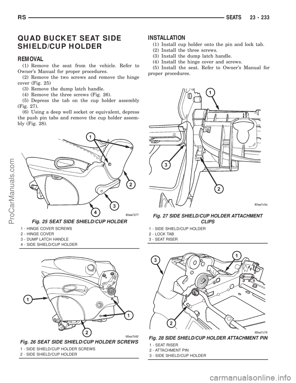
cover (Fig. 25)
(3) Remove the dump latch handle.
(4) Remove the three screws (Fig. 26).
(5) Depress the tab on the cup holder assembly
(Fig. 27).
(6) Using a deep well socket or equivalent, depress
the push pin tabs and remove the cup holder assem-
bly (Fig. 28).
INSTALLATION
(1) Install cup holder onto the pin and lock tab.
(2) Install the three screws.
(3) Install the dump latch handle.
(4) Install the hinge cover and screws.
(5) Install the seat. Refer to Owner's Manual for
proper procedures.
Fig. 25 SEAT SIDE SHIELD/CUP HOLDER
1 - HINGE COVER SCREWS
2 - HINGE COVER
3 - DUMP LATCH HANDLE
4 - SIDE SHIELD/CUP HOLDER
Fig. 26 SEAT SIDE SHIELD/CUP HOLDER SCREWS
1 - SIDE SHIELD/CUP HOLDER SCREWS
2 - SIDE SHIELD/CUP HOLDER
Fig. 27 SIDE SHIELD/CUP HOLDER ATTACHMENT
CLIPS
1 - SIDE SHIELD/CUP HOLDER
2 - LOCK TAB
3 - SEAT RISER
Fig. 28 SIDE SHIELD/CUP HOLDER ATTACHMENT PIN
1 - SEAT RISER
2 - ATTACHMENT PIN
3 - SIDE SHIELD/CUP HOLDER
RSSEATS23 - 233
ProCarManuals.com
Page 2147 of 2321
QUAD BUCKET SEAT SIDE
SHIELD - NO CUP HOLDER
REMOVAL
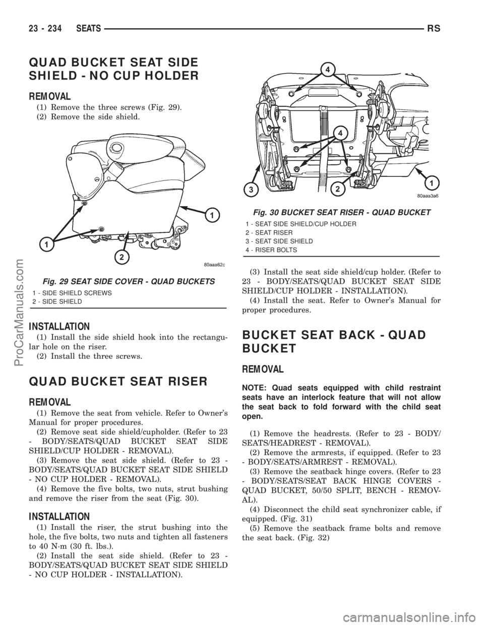
(1) Remove the three screws (Fig. 29).
(2) Remove the side shield.
INSTALLATION
(1) Install the side shield hook into the rectangu-
lar hole on the riser.
(2) Install the three screws.
QUAD BUCKET SEAT RISER
REMOVAL
(1) Remove the seat from vehicle. Refer to Owner's
Manual for proper procedures.
(2) Remove seat side shield/cupholder. (Refer to 23
- BODY/SEATS/QUAD BUCKET SEAT SIDE
SHIELD/CUP HOLDER - REMOVAL).
(3) Remove the seat side shield. (Refer to 23 -
BODY/SEATS/QUAD BUCKET SEAT SIDE SHIELD
- NO CUP HOLDER - REMOVAL).
(4) Remove the five bolts, two nuts, strut bushing
and remove the riser from the seat (Fig. 30).
INSTALLATION
(1) Install the riser, the strut bushing into the
hole, the five bolts, two nuts and tighten all fasteners
to 40 N´m (30 ft. lbs.).
(2) Install the seat side shield. (Refer to 23 -
BODY/SEATS/QUAD BUCKET SEAT SIDE SHIELD
- NO CUP HOLDER - INSTALLATION).(3) Install the seat side shield/cup holder. (Refer to
23 - BODY/SEATS/QUAD BUCKET SEAT SIDE
SHIELD/CUP HOLDER - INSTALLATION).
(4) Install the seat. Refer to Owner's Manual for
proper procedures.
BUCKET SEAT BACK - QUAD
BUCKET
REMOVAL
NOTE: Quad seats equipped with child restraint
seats have an interlock feature that will not allow
the seat back to fold forward with the child seat
open.
(1) Remove the headrests. (Refer to 23 - BODY/
SEATS/HEADREST - REMOVAL).
(2) Remove the armrests, if equipped. (Refer to 23
- BODY/SEATS/ARMREST - REMOVAL).
(3) Remove the seatback hinge covers. (Refer to 23
- BODY/SEATS/SEAT BACK HINGE COVERS -
QUAD BUCKET, 50/50 SPLIT, BENCH - REMOV-
AL).
(4) Disconnect the child seat synchronizer cable, if
equipped. (Fig. 31)
(5) Remove the seatback frame bolts and remove
the seat back. (Fig. 32)
Fig. 29 SEAT SIDE COVER - QUAD BUCKETS
1 - SIDE SHIELD SCREWS
2 - SIDE SHIELD
Fig. 30 BUCKET SEAT RISER - QUAD BUCKET
1 - SEAT SIDE SHIELD/CUP HOLDER
2 - SEAT RISER
3 - SEAT SIDE SHIELD
4 - RISER BOLTS
23 - 234 SEATSRS
ProCarManuals.com