2001 DODGE RAM Fuel pump relay
[x] Cancel search: Fuel pump relayPage 290 of 2889
STANDARD PROCEDURE - BLEEDING
The hydraulic booster is generally self-bleeding,
this procedure will normally bleed the air from the
booster. Normal driving and operation of the unit will
remove any remaining trapped air.
(1) Fill power steering pump reservoir.
(2) Disconnect fuel shutdown relay and crank the
engine for several seconds, Refer to Fuel System for
relay location and WARNING.
(3) Check fluid level and add if necessary.
(4) Connect fuel shutdown relay and start the
engine.
(5) Turn the steering wheel slowly from lock to
lock twice.
(6) Stop the engine and discharge the accumulator
by depressing the brake pedal 5 times.
(7) Start the engine and turn the steering wheel
slowly from lock to lock twice.
(8) Turn off the engine and check fluid level and
add if necessary.
NOTE: If fluid foaming occurs, wait for foam to dis-
sipate and repeat steps 7 and 8.
REMOVAL
NOTE: If the booster is being replaced because the
power steering fluid is contaminated, flush the
power steering system before replacing the booster.
(1) With engine off depress the brake pedal 5
times to discharge the accumulator.
(2) Remove brake lines from master cylinder.
(3) Remove mounting nuts from the master cylin-
der.
(4) Remove the bracket from the hydraulic booster
lines and master cylinder mounting studs.
(5) Remove the master cylinder.
(6) Remove the return hose and the two pressure
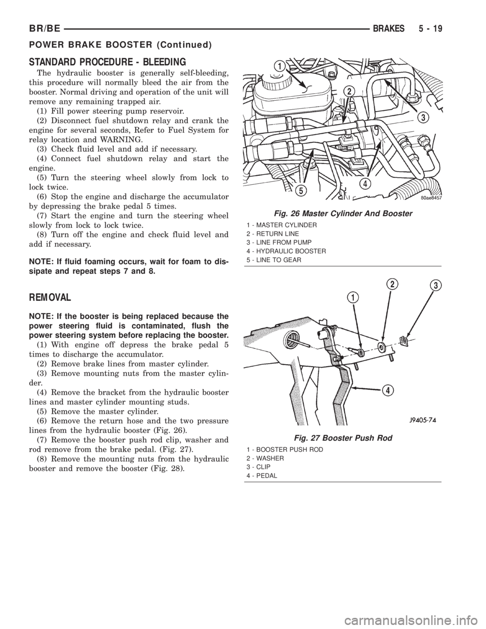
lines from the hydraulic booster (Fig. 26).
(7) Remove the booster push rod clip, washer and
rod remove from the brake pedal. (Fig. 27).
(8) Remove the mounting nuts from the hydraulic
booster and remove the booster (Fig. 28).
Fig. 26 Master Cylinder And Booster
1 - MASTER CYLINDER
2 - RETURN LINE
3 - LINE FROM PUMP
4 - HYDRAULIC BOOSTER
5 - LINE TO GEAR
Fig. 27 Booster Push Rod
1 - BOOSTER PUSH ROD
2 - WASHER
3 - CLIP
4 - PEDAL
BR/BEBRAKES 5 - 19
POWER BRAKE BOOSTER (Continued)
Page 383 of 2889

ENGINE COOLANT TEMP
SENSOR - 3.9L/5.2L/5.9L
DESCRIPTION
The Engine Coolant Temperature (ECT) sensor is
used to sense engine coolant temperature. The sensor
protrudes into an engine water jacket.
The ECT sensor is a two-wire Negative Thermal
Coefficient (NTC) sensor. Meaning, as engine coolant
temperature increases, resistance (voltage) in the
sensor decreases. As temperature decreases, resis-
tance (voltage) in the sensor increases.
OPERATION
At key-on, the Powertrain Control Module (PCM)
sends out a regulated 5 volt signal to the ECT sensor.
The PCM then monitors the signal as it passes
through the ECT sensor to the sensor ground (sensor
return).
When the engine is cold, the PCM will operate in
Open Loop cycle. It will demand slightly richer air-
fuel mixtures and higher idle speeds. This is done
until normal operating temperatures are reached.
The PCM uses inputs from the ECT sensor for the
following calculations:
²for engine coolant temperature gauge operation
through CCD or PCI (J1850) communications
²Injector pulse-width
²Spark-advance curves
²ASD relay shut-down times
²Idle Air Control (IAC) motor key-on steps
²Pulse-width prime-shot during cranking
²O2 sensor closed loop times
²Purge solenoid on/off times
²EGR solenoid on/off times (if equipped)
²Leak Detection Pump operation (if equipped)²Radiator fan relay on/off times (if equipped)
²Target idle speed
REMOVAL
WARNING: HOT, PRESSURIZED COOLANT CAN
CAUSE INJURY BY SCALDING. COOLING SYSTEM
MUST BE PARTIALLY DRAINED BEFORE REMOV-
ING THE COOLANT TEMPERATURE SENSOR.
REFER TO GROUP 7, COOLING.
(1) Partially drain cooling system (Refer to 7 -
COOLING - STANDARD PROCEDURE).
(2) Remove air cleaner assembly.
(3) Disconnect electrical connector from sensor
(Fig. 14).
(4)Engines with air conditioning:When
removing the connector from sensor, do not pull
directly on wiring harness. Fabricate an L-shaped
hook tool from a coat hanger (approximately eight
inches long). Place the hook part of tool under the
connector for removal. The connector is snapped onto
the sensor. It is not equipped with a lock type tab.
(5) Remove sensor from intake manifold.
INSTALLATION
(1) Install sensor.
(2) Tighten to 6±8 N´m (55±75 in. lbs.) torque.
(3) Connect electrical connector to sensor. The sen-
sor connector is symmetrical (not indexed). It can be
installed to the sensor in either direction.
(4) Install air cleaner assembly.
(5) Refill cooling system (Refer to 7 - COOLING -
STANDARD PROCEDURE).
Fig. 13 Block HeaterÐDiesel Engine
1 - BLOCK HEATER
Fig. 14 Engine Coolant Temperature
1 - GENERATOR
2 - A/C COMPRESSOR
3 - ENGINE COOLANT TEMPERATURE SENSOR
4 - ELEC. CONN.
7 - 48 ENGINEBR/BE
ENGINE BLOCK HEATER - 5.9L DIESEL (Continued)
Page 465 of 2889

NOTE: ECM Outputs:
After inputs are received by the ECM, certain sen-
sors, switches and components are controlled or reg-
ulated by the ECM. These are consideredECM
Outputs.These outputs are for:
²CCD bus (+) circuits
²CCD bus (-) circuits
²CKP and APPS outputs to the PCM
²Data link connection for DRB scan tool
²Five volt sensor supply
²Fuel injection pump
²Fuel injection pump relay
²(FPCM) Fuel Pump Control Module
²Fuel transfer (lift) pump
²Intake manifold air heater relays #1 and #2 con-
trol circuits
²Malfunction indicator lamp (Check engine lamp)
²Oil pressure gauge/warning lamp
²PCM
²Wait-to-start warning lamp
²Water-In-Fuel (WIF) warning lamp
REMOVAL
The ECM is bolted to the engine block behind the
fuel filter (Fig. 16).
(1) Record any Diagnostic Trouble Codes (DTC's)
found in the PCM or ECM.To avoid possible voltage spike damage to either
the Powertrain Control Module (PCM) or ECM, igni-
tion key must be off, and negative battery cables
must be disconnected before unplugging ECM con-
nectors.
(2) Disconnect both negative battery cables at both
batteries.
(3) Remove 50±way electrical connector bolt at
ECM (Fig. 16). Note: Connector bolt is female 4mm
hex head. To remove bolt, use a ball-hex bit or ball-
hex screwdriver such as Snap-Ont4mm SDABM4
(5/32º may also be used). As bolt is being removed,
very carefully remove connector from ECM.
(4) Remove three ECM mounting bolts and remove
ECM from vehicle.
INSTALLATION
Do not apply paint to back of ECM. Poor ground
will result.
(1) Clean ECM mounting points at engine block.
(2) Position ECM to engine block and install 3
mounting bolts. Tighten bolts to 24 N´m (18 ft. lbs.).
(3) Check pin connectors in ECM and 50±way con-
nector for corrosion or damage. Repair as necessary.
(4) Clean pins in 50±way electrical connector with
a quick-dry electrical contact cleaner.
(5) Very carefully install 50±way connector to
ECM. Tighten connector hex bolt.
(6) Install battery cables.
(7)Turn key to ON position. Without starting
engine, slowly press throttle pedal to floor and
then slowly release. This step must be done
(one time) to ensure accelerator pedal position
sensor calibration has been learned by ECM. If
not done, possible DTC's may be set.
(8) Use DRB scan tool to erase any stored compan-
ion DTC's from PCM.
POWERTRAIN CONTROL
MODULE
DESCRIPTION - PCM
The Powertrain Control Module (PCM) is located
in the engine compartment (Fig. 17). The PCM is
referred to as JTEC.
DESCRIPTION - MODES OF OPERATION
As input signals to the Powertrain Control Module
(PCM) change, the PCM adjusts its response to the
output devices. For example, the PCM must calculate
different injector pulse width and ignition timing for
idle than it does for wide open throttle (WOT).
The PCM will operate in two different modes:
Open Loop and Closed Loop.
Fig. 16 Engine Control Module (ECM) Location and
Mounting
1 - ENGINE CONTROL MODULE (ECM)
2 - HEX HEADED BOLT
3 - 50-WAY CONNECTOR
4 - FUEL TRANSFER PUMP
5 - MOUNTING BOLTS (3)
8E - 14 ELECTRONIC CONTROL MODULESBR/BE
ENGINE CONTROL MODULE (Continued)
Page 466 of 2889

During Open Loop modes, the PCM receives input
signals and responds only according to preset PCM
programming. Input from the oxygen (O2S) sensors
is not monitored during Open Loop modes.
During Closed Loop modes, the PCM will monitor
the oxygen (O2S) sensors input. This input indicates
to the PCM whether or not the calculated injector
pulse width results in the ideal air-fuel ratio. This
ratio is 14.7 parts air-to-1 part fuel. By monitoring
the exhaust oxygen content through the O2S sensor,
the PCM can fine tune the injector pulse width. This
is done to achieve optimum fuel economy combined
with low emission engine performance.
The fuel injection system has the following modes
of operation:
²Ignition switch ON
²Engine start-up (crank)
²Engine warm-up
²Idle
²Cruise
²Acceleration
²Deceleration
²Wide open throttle (WOT)
²Ignition switch OFF
The ignition switch On, engine start-up (crank),
engine warm-up, acceleration, deceleration and wide
open throttle modes are Open Loop modes. The idle
and cruise modes, (with the engine at operating tem-
perature) are Closed Loop modes.
IGNITION SWITCH (KEY-ON) MODE
This is an Open Loop mode. When the fuel system
is activated by the ignition switch, the following
actions occur:²The PCM pre-positions the idle air control (IAC)
motor.
²The PCM determines atmospheric air pressure
from the MAP sensor input to determine basic fuel
strategy.
²The PCM monitors the engine coolant tempera-
ture sensor input. The PCM modifies fuel strategy
based on this input.
²Intake manifold air temperature sensor input is
monitored.
²Throttle position sensor (TPS) is monitored.
²The auto shutdown (ASD) relay is energized by
the PCM for approximately three seconds.
²The fuel pump is energized through the fuel
pump relay by the PCM. The fuel pump will operate
for approximately three seconds unless the engine is
operating or the starter motor is engaged.
²The O2S sensor heater element is energized via
the ASD relay. The O2S sensor input is not used by
the PCM to calibrate air-fuel ratio during this mode
of operation.
ENGINE START-UP MODE
This is an Open Loop mode. The following actions
occur when the starter motor is engaged.
The PCM receives inputs from:
²Battery voltage
²Engine coolant temperature sensor
²Crankshaft position sensor
²Intake manifold air temperature sensor
²Manifold absolute pressure (MAP) sensor
²Throttle position sensor (TPS)
²Starter motor relay
²Camshaft position sensor signal
The PCM monitors the crankshaft position sensor.
If the PCM does not receive a crankshaft position
sensor signal within 3 seconds of cranking the
engine, it will shut down the fuel injection system.
The fuel pump is activated by the PCM through
the fuel pump relay.
Voltage is applied to the fuel injectors with the
ASD relay via the PCM. The PCM will then control
the injection sequence and injector pulse width by
turning the ground circuit to each individual injector
on and off.
The PCM determines the proper ignition timing
according to input received from the crankshaft posi-
tion sensor.
ENGINE WARM-UP MODE
This is an Open Loop mode. During engine warm-
up, the PCM receives inputs from:
²Battery voltage
²Crankshaft position sensor
²Engine coolant temperature sensor
²Intake manifold air temperature sensor
Fig. 17 PCM Location
1 - PCM MOUNTING BOLTS (3)
2 - POWERTRAIN CONTROL MODULE (PCM)
3 - (3) 32±WAY CONNECTORS
BR/BEELECTRONIC CONTROL MODULES 8E - 15
POWERTRAIN CONTROL MODULE (Continued)
Page 468 of 2889

²Camshaft position sensor signal (in the distribu-
tor)
²Park/neutral switch (gear indicator signalÐauto.
trans. only)
²Vehicle speed sensor
If the vehicle is under hard deceleration with the
proper rpm and closed throttle conditions, the PCM
will ignore the oxygen sensor input signal. The PCM
will enter a fuel cut-off strategy in which it will not
supply a ground to the injectors. If a hard decelera-
tion does not exist, the PCM will determine the
proper injector pulse width and continue injection.
Based on the above inputs, the PCM will adjust
engine idle speed through the idle air control (IAC)
motor.
The PCM adjusts ignition timing by turning the
ground path to the coil on and off.
WIDE OPEN THROTTLE MODE
This is an Open Loop mode. During wide open
throttle operation, the PCM receives the following
inputs.
²Battery voltage
²Crankshaft position sensor
²Engine coolant temperature sensor
²Intake manifold air temperature sensor
²Manifold absolute pressure (MAP) sensor
²Throttle position sensor (TPS)
²Camshaft position sensor signal (in the distribu-
tor)
During wide open throttle conditions, the following
occurs:
²Voltage is applied to the fuel injectors with the
ASD relay via the PCM. The PCM will then control
the injection sequence and injector pulse width by
turning the ground circuit to each individual injector
on and off. The PCM ignores the oxygen sensor input
signal and provides a predetermined amount of addi-
tional fuel. This is done by adjusting injector pulse
width.
²The PCM adjusts ignition timing by turning the
ground path to the coil on and off.
IGNITION SWITCH OFF MODE
When ignition switch is turned to OFF position,
the PCM stops operating the injectors, ignition coil,
ASD relay and fuel pump relay.
DESCRIPTION - 5 VOLT SUPPLIES
Two different Powertrain Control Module (PCM)
five volt supply circuits are used; primary and sec-
ondary.
DESCRIPTION - IGNITION CIRCUIT SENSE
This circuit ties the ignition switch to the Power-
train Control Module (PCM).
DESCRIPTION - POWER GROUNDS
The Powertrain Control Module (PCM) has 2 main
grounds. Both of these grounds are referred to as
power grounds. All of the high-current, noisy, electri-
cal devices are connected to these grounds as well as
all of the sensor returns. The sensor return comes
into the sensor return circuit, passes through noise
suppression, and is then connected to the power
ground.
The power ground is used to control ground cir-
cuits for the following PCM loads:
²Generator field winding
²Fuel injectors
²Ignition coil(s)
²Certain relays/solenoids
²Certain sensors
DESCRIPTION - SENSOR RETURN
The Sensor Return circuits are internal to the Pow-
ertrain Control Module (PCM).
Sensor Return provides a low±noise ground refer-
ence for all engine control system sensors. Refer to
Power Grounds for more information.
DESCRIPTION - SIGNAL GROUND
Signal ground provides a low noise ground to the
data link connector.
OPERATION - PCM - GAS ENGINES
The PCM operates the fuel system. The PCM is a
pre-programmed, triple microprocessor digital com-
puter. It regulates ignition timing, air-fuel ratio,
emission control devices, charging system, certain
transmission features, speed control, air conditioning
compressor clutch engagement and idle speed. The
PCM can adapt its programming to meet changing
operating conditions.
The PCM receives input signals from various
switches and sensors. Based on these inputs, the
PCM regulates various engine and vehicle operations
through different system components. These compo-
nents are referred to as Powertrain Control Module
(PCM) Outputs. The sensors and switches that pro-
vide inputs to the PCM are considered Powertrain
Control Module (PCM) Inputs.
The PCM adjusts ignition timing based upon
inputs it receives from sensors that react to: engine
rpm, manifold absolute pressure, engine coolant tem-
perature, throttle position, transmission gear selec-
tion (automatic transmission), vehicle speed and the
brake switch.
The PCM adjusts idle speed based on inputs it
receives from sensors that react to: throttle position,
vehicle speed, transmission gear selection, engine
coolant temperature and from inputs it receives from
the air conditioning clutch switch and brake switch.
BR/BEELECTRONIC CONTROL MODULES 8E - 17
POWERTRAIN CONTROL MODULE (Continued)
Page 469 of 2889

Based on inputs that it receives, the PCM adjusts
ignition coil dwell. The PCM also adjusts the gener-
ator charge rate through control of the generator
field and provides speed control operation.
NOTE: PCM Inputs:
²A/C request (if equipped with factory A/C)
²A/C select (if equipped with factory A/C)
²Auto shutdown (ASD) sense
²Battery temperature
²Battery voltage
²Brake switch
²CCD bus (+) circuits
²CCD bus (-) circuits
²Camshaft position sensor signal
²Crankshaft position sensor
²Data link connection for DRB scan tool
²Engine coolant temperature sensor
²Fuel level
²Generator (battery voltage) output
²Ignition circuit sense (ignition switch in on/off/
crank/run position)
²Intake manifold air temperature sensor
²Leak detection pump (switch) sense (if equipped)
²Manifold absolute pressure (MAP) sensor
²Oil pressure
²Output shaft speed sensor
²Overdrive/override switch
²Oxygen sensors
²Park/neutral switch (auto. trans. only)
²Power ground
²Sensor return
²Signal ground
²Speed control multiplexed single wire input
²Throttle position sensor
²Transmission governor pressure sensor
²Transmission temperature sensor
²Vehicle speed inputs from ABS or RWAL system
NOTE: PCM Outputs:
²A/C clutch relay
²Auto shutdown (ASD) relay
²CCD bus (+/-) circuits for: speedometer, voltme-
ter, fuel gauge, oil pressure gauge/lamp, engine temp.
gauge and speed control warn. lamp
²Data link connection for DRB scan tool
²EGR valve control solenoid (if equipped)
²EVAP canister purge solenoid
²Five volt sensor supply (primary)
²Five volt sensor supply (secondary)
²Fuel injectors
²Fuel pump relay
²Generator field driver (-)
²Generator field driver (+)
²Generator lamp (if equipped)²Idle air control (IAC) motor
²Ignition coil
²Leak detection pump (if equipped)
²Malfunction indicator lamp (Check engine lamp).
Driven through CCD circuits.
²Overdrive indicator lamp (if equipped)
²Service Reminder Indicator (SRI) Lamp (MAINT
REQ'D lamp). Driven through CCD circuits.
²Speed control vacuum solenoid
²Speed control vent solenoid
²Tachometer (if equipped). Driven through CCD
circuits.
²Transmission convertor clutch circuit
²Transmission 3±4 shift solenoid
²Transmission relay
²Transmission temperature lamp (if equipped)
²Transmission variable force solenoid
OPERATION - DIESEL
Two different control modules are used: The Pow-
ertrain Control Module (PCM), and the Engine Con-
trol Module (ECM). The ECMcontrolsthe fuel
system. The PCMdoes not controlthe fuel system.
The PCM's main function is to control: the vehicle
charging system, speed control system, transmission,
air conditioning system and certain bussed messages.
The PCM can adapt its programming to meet
changing operating conditions.
The PCM receives input signals from various
switches and sensors. Based on these inputs, the
PCM regulates various engine and vehicle operations
through different system components. These compo-
nents are referred to asPCM Outputs.The sensors
and switches that provide inputs to the PCM are con-
sideredPCM Inputs.
NOTE: PCM Inputs:
²A/C request (if equipped with factory A/C)
²A/C select (if equipped with factory A/C)
²Accelerator Pedal Position Sensor (APPS) output
from ECM
²Auto shutdown (ASD) relay sense
²Battery temperature sensor
²Battery voltage
²Brake switch
²CCD bus (+) circuits
²CCD bus (-) circuits
²Crankshaft Position Sensor (CKP) output from
ECM
²Data link connection for DRB scan tool
²Fuel level sensor
²Generator (battery voltage) output
²Ignition sense
²Output shaft speed sensor
²Overdrive/override switch
²Park/neutral switch (auto. trans. only)
8E - 18 ELECTRONIC CONTROL MODULESBR/BE
POWERTRAIN CONTROL MODULE (Continued)
Page 491 of 2889
DIESEL ENGINE
Diesel engine models feature a clamping type
female battery terminal made of soft lead die cast
onto one end of the battery cable wire. A square
headed pinch-bolt and hex nut are installed at the
open end of the female battery terminal clamp. The
pinch-bolt on the left side battery positive cable
female terminal clamp also has a stud extending
from the head of the bolt. Large eyelet type terminals
are crimped onto the opposite end of the battery
cable wire and then solder-dipped. The battery posi-
tive cable wires have a red insulating jacket to pro-
vide visual identification and feature a larger female
battery terminal clamp to allow connection to the
larger battery positive terminal post. The battery
negative cable wires have a black insulating jacket
and a smaller female battery terminal clamp.
OPERATION
The battery cables connect the battery terminal
posts to the vehicle electrical system. These cables
also provide a return path for electrical current gen-
erated by the charging system for restoring the volt-
age potential of the battery. The female battery
terminal clamps on the ends of the battery cable
wires provide a strong and reliable connection of the
battery cable to the battery terminal posts. The ter-
minal pinch bolts allow the female terminal clamps
to be tightened around the male terminal posts on
the top of the battery. The eyelet terminals secured
to the ends of the battery cable wires opposite the
female battery terminal clamps provide secure and
reliable connection of the battery to the vehicle elec-
trical system.
GASOLINE ENGINE
The battery positive cable terminal clamp is
crimped onto the ends of two wires. One wire has an
eyelet terminal that connects the battery positive
cable to the B(+) terminal stud of the Power Distri-
bution Center (PDC), and the other wire has an eye-
let terminal that connects the battery positive cable
to the B(+) terminal stud of the engine starter motor
solenoid. The battery negative cable terminal clamp
is also crimped onto the ends of two wires. One wire
has an eyelet terminal that connects the battery neg-
ative cable to the vehicle powertrain through a stud
on the front of the left engine cylinder head. The
other wire has an eyelet terminal that connects the
battery negative cable to the vehicle body through a
ground screw on the left front fender inner shield,
just ahead of the battery. An additional ground wire
with two eyelet terminals is used to provide ground
to the vehicle frame. One eyelet terminal of this
ground wire is installed under the head of the bat-
tery negative cable terminal clamp pinch-bolt, andthe other eyelet terminal is secured with a ground
screw to the outer surface of the left frame rail,
below the battery.
DIESEL ENGINE
The left battery positive cable terminal clamp is
die cast onto the ends of two wires. One wire has an
eyelet terminal that connects the left battery positive
cable to the B(+) terminal stud of the Power Distri-
bution Center (PDC), and the other wire has an eye-
let terminal that connects the left battery positive
cable to the B(+) terminal stud of the engine starter
motor solenoid. The right battery positive cable ter-
minal clamp is die cast onto the end of a single wire.
The eyelet terminal on the other end of the right bat-
tery positive cable is connected to the stud on the
pinch-bolt of the left battery positive cable terminal
clamp. This stud also provides a connection point for
the eyelet terminals from the fuel heater relay and
intake air heater relay jumper harness take outs. All
of these eyelet terminals are secured to the left bat-
tery positive cable terminal clamp pinch-bolt stud
with a single hex nut.
The left battery negative cable terminal clamp is
die cast onto the ends of two wires. One wire has an
eyelet terminal that connects the left battery nega-
tive cable to the vehicle powertrain through a ground
screw on the left side of the engine block, below the
power steering and vacuum pumps. The other wire
has an eyelet terminal that connects the left battery
negative cable to the vehicle body through a ground
screw on the left front fender inner shield, just ahead
of the left battery. An additional ground wire with
two eyelet terminals is used to provide ground to the
vehicle frame. One eyelet terminal of this ground
wire is installed under the nut of the left battery
negative cable terminal clamp pinch-bolt, and the
other eyelet terminal is secured with a ground screw
to the outer surface of the left frame rail, below the
left battery. The right battery negative cable terminal
is also die cast onto the ends of two wires. One wire
has an eyelet terminal that connects the right bat-
tery negative cable to the vehicle powertrain through
a ground screw on the right side of the engine block,
just forward of the right engine mount. The other
wire has an eyelet terminal that connects the right
battery negative cable to the vehicle body through a
ground screw on the right front fender inner shield,
just behind the right battery.
DIAGNOSIS & TESTING - BATTERY CABLES
A voltage drop test will determine if there is exces-
sive resistance in the battery cable terminal connec-
tions or the battery cables. If excessive resistance is
found in the battery cable connections, the connec-
tion point should be disassembled, cleaned of all cor-
8F - 20 BATTERY SYSTEMBR/BE
BATTERY CABLE (Continued)
Page 506 of 2889
(4) Verify that all lamps and accessories are
turned off.
(5) To prevent a gasoline engine from starting,
remove Automatic ShutDown (ASD) relay. To prevent
a diesel engine from starting, remove Fuel Pump
Relay. These relays are located in Power Distribution
Center (PDC). Refer to label on PDC cover for relay
location.
WARNING: IF EQUIPPED WITH DIESEL ENGINE,
ATTEMPT TO START ENGINE A FEW TIMES
BEFORE PROCEEDING WITH FOLLOWING STEP.
(6) Rotate and hold ignition switch in Start posi-
tion. Note cranking voltage and current (amperage)
draw readings shown on volt-ampere tester.
(a) If voltage reads below 9.6 volts, refer to
Starter Motorin Diagnosis and Testing. If starter
motor is OK, refer toEngine Diagnosisin 9,
Engine for further testing of engine. If starter
motor is not OK, replace faulty starter motor.
(b) If voltage reads above 9.6 volts and current
(amperage) draw reads below specifications, refer
toFeed Circuit Testin this section.
(c) If voltage reads 12.5 volts or greater and
starter motor does not turn, refer toControl Cir-
cuit Testingin this section.
(d) If voltage reads 12.5 volts or greater and
starter motor turns very slowly, refer toFeed Cir-
cuit Testin this section.
NOTE: A cold engine will increase starter current
(amperage) draw reading, and reduce battery volt-
age reading.FEED CIRCUIT TEST
The starter feed circuit test (voltage drop method)
will determine if there is excessive resistance in
high-amperage feed circuit. For complete starter wir-
ing circuit diagrams, refer 8, Wiring Diagrams.
When performing these tests, it is important to
remember that voltage drop is giving an indication of
resistance between two points at which voltmeter
probes are attached.
Example:When testing resistance of battery posi-
tive cable, touch voltmeter leads to battery positive
cable clamp and cable connector at starter solenoid.
If you probe battery positive terminal post and cable
connector at starter solenoid, you are reading com-
bined voltage drop in battery positive cable clamp-to-
terminal post connection and battery positive cable.
The following operation will require a voltmeter
accurate to 1/10 (0.10) volt. Before performing tests,
be certain that following procedures are accom-
plished:
²Battery is fully-charged and load-tested. Refer to
Batteryin 8, Battery.
²Fully engage parking brake.
²If equipped with manual transmission, place
gearshift selector lever in Neutral position and block
clutch pedal in fully depressed position. If equipped
with automatic transmission, place gearshift selector
lever in Park position.
²Verify that all lamps and accessories are turned
off.
²To prevent a gasoline engine from starting,
remove Automatic ShutDown (ASD) relay. To prevent
a diesel engine from starting, remove Fuel Pump
Relay. These relays are located in Power Distribution
Center (PDC). Refer to label on PDC cover for relay
location.
(1) Connect positive lead of voltmeter to battery
negative terminal post. Connect negative lead of volt-
meter to battery negative cable clamp (Fig. 2). Rotate
and hold ignition switch in Start position. Observe
voltmeter. If voltage is detected, correct poor contact
between cable clamp and terminal post.Note: If
equipped with a dual battery system (diesel),
procedure must be performed twice, once for
each battery.
(2) Connect positive lead of voltmeter to battery
positive terminal post. Connect negative lead of volt-
meter to battery positive cable clamp (Fig. 3). Rotate
and hold ignition switch in Start position. Observe
voltmeter. If voltage is detected, correct poor contact
between cable clamp and terminal post.Note: If
equipped with a dual battery system (diesel),
this procedure must be performed twice, once
for each battery.
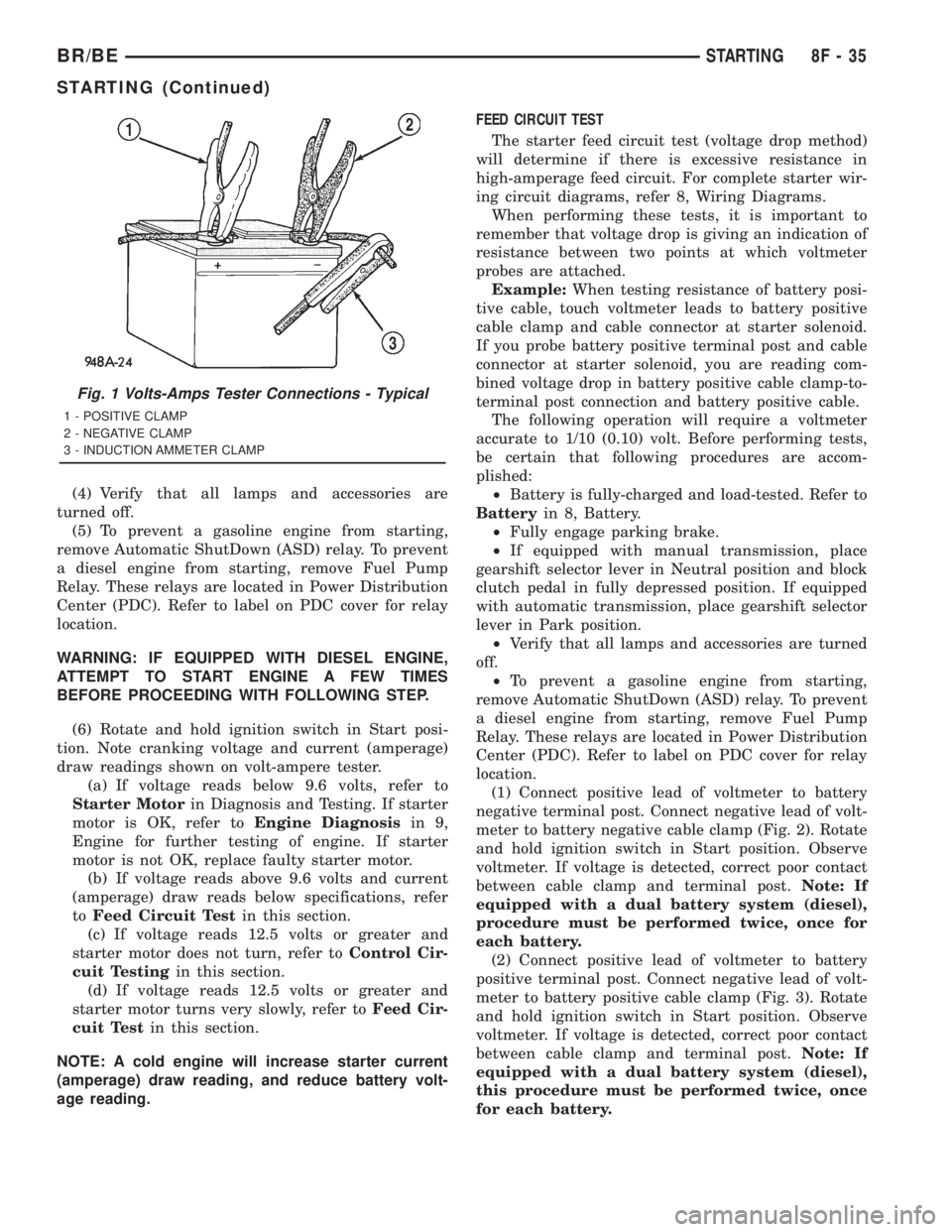
Fig. 1 Volts-Amps Tester Connections - Typical
1 - POSITIVE CLAMP
2 - NEGATIVE CLAMP
3 - INDUCTION AMMETER CLAMP
BR/BESTARTING 8F - 35
STARTING (Continued)