2001 DODGE RAM Fuel pump relay
[x] Cancel search: Fuel pump relayPage 1490 of 2889
(4) Connect the 0-414 kPa (0-60 psi) fuel pressure
test gauge (from Gauge Set 5069) to the test port on
the appropriate Adaptor Tool.The DRBtIII Scan
Tool along with the PEP module, the 500 psi
pressure transducer, and the transducer-to-test
port adapter may also be used in place of the
fuel pressure gauge.
The fittings on both tools must be in good
condition and free from any small leaks before
performing the proceeding test.
(5) Start engine and bring to normal operating
temperature.
(6) Observe test gauge. Normal operating pressure
should be 339 kPa +/±34 kPa (49.2 psi +/±5 psi).
(7) Shut engine off.
(8) Pressure should not fall below30 psi for five
minutes.
(9) If pressure falls below 30 psi, it must be deter-
mined if a fuel injector, the check valve within the
fuel pump module, or a fuel tube/line is leaking.
(10) Again, start engine and bring to normal oper-
ating temperature.
(11) Shut engine off.
(12)Testing for fuel injector or fuel rail leak-
age:Clamp off the rubber hose portion of Adaptor
Tool between the fuel rail and the test port ªTº on
Adapter Tool. If pressure now holds at or above 30
psi, a fuel injector or the fuel rail is leaking.
(13)Testing for fuel pump check valve, filter/
regulator check valve or fuel tube/line leakage:
Clamp off the rubber hose portion of Adaptor Tool
between the vehicle fuel line and test port ªTº on
Adapter Tool. If pressure now holds at or above 30
psi, a leak may be found at a fuel tube/line. If no
leaks are found at fuel tubes or lines, one of the
check valves in either the electric fuel pump or filter/
regulator may be leaking.
Note: A quick loss of pressure usually indicates a
defective check valve in the filter/regulator. A slow
loss of pressure usually indicates a defective check
valve in the electric fuel pump.
The electric fuel pump is not serviced separately.
Replace the fuel pump module assembly. The filter/
regulator may be replaced separately on certain
applications. Refer to Fuel Filter/Fuel Pressure Reg-
ulator Removal/Installation for additional informa-
tion.STANDARD PROCEDURE - FUEL SYSTEM
PRESSURE RELEASE
Use following procedure if the fuel injector
rail is, or is not equipped with a fuel pressure
test port.
(1) Remove fuel fill cap.
(2) Remove fuel pump relay from Power Distribu-
tion Center (PDC). For location of relay, refer to label
on underside of PDC cover.
(3) Start and run engine until it stalls.
(4) Attempt restarting engine until it will no
longer run.
(5) Turn ignition key to OFF position.
CAUTION: Steps 1, 2, 3 and 4 must be performed to
relieve high pressure fuel from within fuel rail. Do
not attempt to use following steps to relieve this
pressure as excessive fuel will be forced into a cyl-
inder chamber.
(6) Unplug connector from any fuel injector.
(7) Attach one end of a jumper wire with alligator
clips (18 gauge or smaller) to either injector terminal.
(8) Connect other end of jumper wire to positive
side of battery.
(9) Connect one end of a second jumper wire to
remaining injector terminal.
CAUTION: Powering an injector for more than a few
seconds will permanently damage the injector.
(10) Momentarily touch other end of jumper wire
to negative terminal of battery for no more than a
few seconds.
(11) Place a rag or towel below fuel line quick-con-
nect fitting at fuel rail.
(12) Disconnect quick-connect fitting at fuel rail.
Refer to Quick-Connect Fittings.
(13) Return fuel pump relay to PDC.
(14) One or more Diagnostic Trouble Codes (DTC's)
may have been stored in PCM memory due to fuel
pump relay removal. The DRBtscan tool must be
used to erase a DTC.
BR/BEFUEL DELIVERY - GASOLINE 14 - 3
FUEL DELIVERY - GASOLINE (Continued)
Page 1496 of 2889
INSTALLATION
The fuel gauge sending unit (fuel level sensor) and
float assembly is located on the side of fuel pump
module (Fig. 9). The fuel pump module is located
inside of fuel tank.
(1) Position sending unit into tracks. Note wire
routing.
(2) Push unit on tracks until lock tab snaps into
notch.
(3) Connect 2 sending unit wires into 4±way con-
nector and install locking collar.
(4) Connect 4±way electrical connector to module.
(5) Install fuel pump module. Refer to Fuel Pump
Module Removal/Installation.
(6) Install fuel tank. Refer to Fuel Tank±All
Engines in the Removal/Installation section.
FUEL LINES
DESCRIPTION
Also refer to Quick-Connect Fittings.
WARNING: THE FUEL SYSTEM IS UNDER A CON-
STANT PRESSURE (EVEN WITH THE ENGINE OFF).
BEFORE SERVICING ANY FUEL SYSTEM HOSES, FIT-
TINGS OR LINES, THE FUEL SYSTEM PRESSURE
MUST BE RELEASED. REFER TO THE FUEL SYSTEM
PRESSURE RELEASE PROCEDURE IN THIS GROUP.
The lines/tubes/hoses used on fuel injected vehicles
are of a special construction. This is due to the
higher fuel pressures and the possibility of contami-
nated fuel in this system. If it is necessary to replace
these lines/tubes/hoses, only those marked EFM/EFI
may be used.
If equipped:The hose clamps used to secure rub-
ber hoses on fuel injected vehicles are of a special
rolled edge construction. This construction is used to
prevent the edge of the clamp from cutting into the
hose. Only these rolled edge type clamps may be
used in this system. All other types of clamps may
cut into the hoses and cause high-pressure fuel leaks.
Use new original equipment type hose clamps.
FUEL PUMP
DESCRIPTION
The fuel pump is located inside of the fuel pump
module. A 12 volt, permanent magnet, electric motor
powers the fuel pump.
OPERATION
Voltage to operate the electric pump is supplied
through the fuel pump relay.Fuel is drawn in through a filter at the bottom of
the module and pushed through the electric motor
gearset to the pump outlet.
Check Valve Operation:The pump outlet con-
tains a one-way check valve to prevent fuel flow back
into the tank and to maintain fuel supply line pres-
sure (engine warm) when pump is not operational. It
is also used to keep the fuel supply line full of gaso-
line when pump is not operational. After the vehicle
has cooled down, fuel pressure may drop to 0 psi
(cold fluid contracts), but liquid gasoline will remain
in fuel supply line between the check valve and fuel
injectors.Fuel pressure that has dropped to 0
psi on a cooled down vehicle (engine off) is a
normal condition.Refer to the Fuel Pressure Leak
Down Test for more information.
DIAGNOSIS AND TESTING - FUEL PUMP
CAPACITY TEST
Before performing this test, verify fuel pump
pressure. Refer to Fuel Pump Pressure Test.
Use this test in conjunction with the Fuel Pres-
sure Leak Down Test.
(1) Release fuel system pressure. Refer to Fuel
Pressure Release Procedure.
(2) Disconnect fuel supply line at fuel rail. Refer to
Quick-Connect Fittings. Some engines may require
air cleaner housing removal before line disconnection.
(3) Obtain correct Fuel Line Pressure Test Adapter
Tool Hose. Tool number 6539 is used for 5/16º fuel
lines and tool number 6631 is used for 3/8º fuel lines.
(4)
Connect correct Fuel Line Pressure Test Adapter
Tool Hose into disconnected fuel supply line. Insert other
end of Adaptor Tool Hose into a graduated container.
(5) Remove fuel fill cap.
(6) To activate fuel pump and pressurize system,
obtain DRBtscan tool and actuate ASD Fuel System
Test.
(7) A good fuel pump will deliver at least 1/4 liter
of fuel in 7 seconds. Do not operate fuel pump for
longer than 7 seconds with fuel line disconnected as
fuel pump module reservoir may run empty.
(a) If capacity is lower than specification, but
fuel pump can be heard operating through fuel fill
cap opening, check for a kinked/damaged fuel sup-
ply line somewhere between fuel rail and fuel
pump module.
(b) If line is not kinked/damaged, and fuel pres-
sure is OK, but capacity is low, replace fuel filter/
fuel pressure regulator. The filter/regulator may be
serviced separately on certain applications. Refer
to Fuel Filter/Fuel Pressure Regulator Removal/In-
stallation for additional information.
(c) If both fuel pressure and capacity are low,
replace fuel pump module assembly. Refer to Fuel
Pump Module Removal/Installation.
BR/BEFUEL DELIVERY - GASOLINE 14 - 9
FUEL LEVEL SENDING UNIT / SENSOR (Continued)
Page 1498 of 2889
(1) Be sure fuel tank contains fuel before starting
test. If tank is empty or near empty, amperage read-
ings will be incorrect.
(2) Obtain LCS adapter.
(3) Plug cable from LCS adapter into DRB scan
tool at SET 1 receptacle.
(4) Plug DRB into vehicle 16±way connector (data
link connector).
(5) Connect (-) and (+) test cable leads into LCS
adapter receptacles. Use10 amp (10A +)receptacle
and common (-) receptacles.
(6) Gain access to MAIN MENU on DRB screen.
(7) Press DVOM button on DRB.
(8) Using left/right arrow keys, highlight CHAN-
NEL 1 function on DRB screen.
(9) Press ENTER three times.
(10) Using up/down arrow keys, highlight RANGE
on DRB screen (screen will default to 2 amp scale).
(11) Press ENTER to change 2 amp scale to 10
amp scale.This step must be done to prevent
damage to DRB scan tool or LCS adapter
(blown fuse).
(12) Remove cover from Power Distribution Center
(PDC).
(13) Remove fuel pump relay from PDC. Refer to
label on PDC cover for relay location.
WARNING: BEFORE PROCEEDING TO NEXT STEP,
NOTE THE FUEL PUMP WILL BE ACTIVATED AND
SYSTEM PRESSURE WILL BE PRESENT. THIS WILL
OCCUR AFTER CONNECTING TEST LEADS FROM
LCS ADAPTER INTO FUEL PUMP RELAY CAVITIES.
THE FUEL PUMP WILL OPERATE EVEN WITH IGNI-
TION KEY IN OFF POSITION. BEFORE ATTACHING
TEST LEADS, BE SURE ALL FUEL LINES AND
FUEL SYSTEM COMPONENTS ARE CONNECTED.
CAUTION: To prevent possible damage to the vehi-
cle electrical system and LCS adapter, the test
leads must be connected into relay cavities exactly
as shown in following steps.
Depending upon vehicle model, year or engine con-
figuration, three different types of relays may be
used: Type-1, type-2 and type±3.
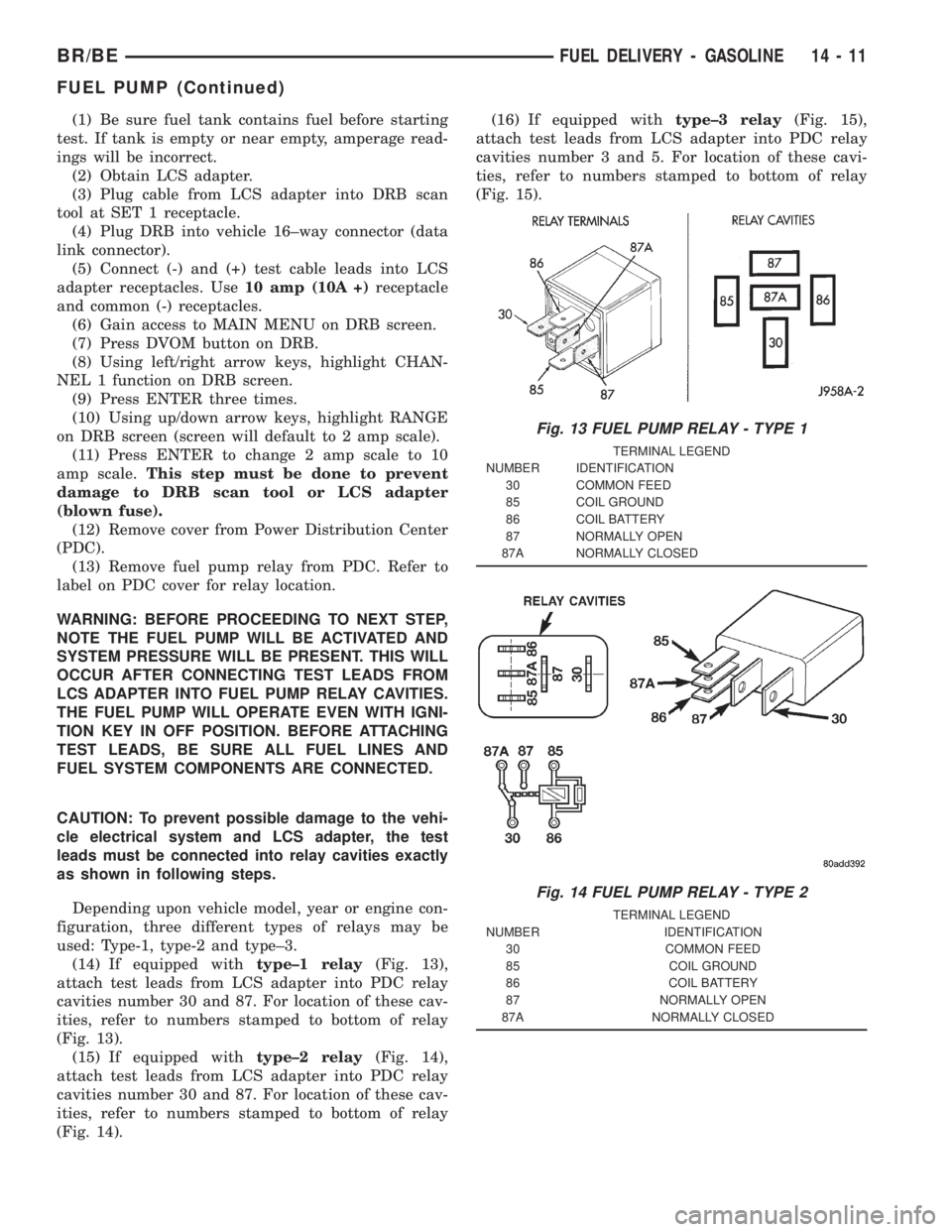
(14) If equipped withtype±1 relay(Fig. 13),
attach test leads from LCS adapter into PDC relay
cavities number 30 and 87. For location of these cav-
ities, refer to numbers stamped to bottom of relay
(Fig. 13).
(15) If equipped withtype±2 relay(Fig. 14),
attach test leads from LCS adapter into PDC relay
cavities number 30 and 87. For location of these cav-
ities, refer to numbers stamped to bottom of relay
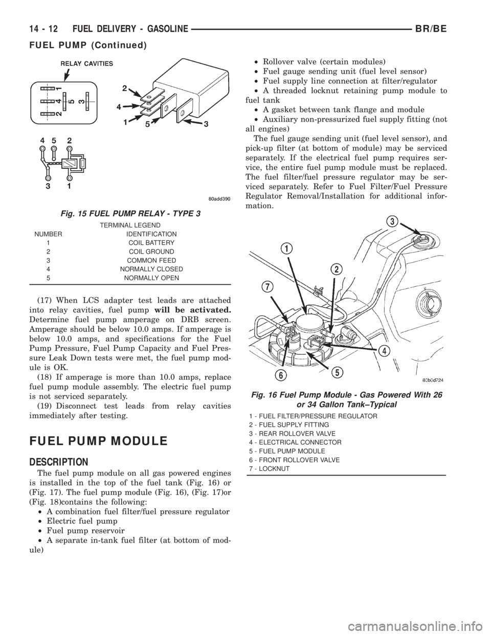
(Fig. 14).(16) If equipped withtype±3 relay(Fig. 15),
attach test leads from LCS adapter into PDC relay
cavities number 3 and 5. For location of these cavi-
ties, refer to numbers stamped to bottom of relay
(Fig. 15).
Fig. 13 FUEL PUMP RELAY - TYPE 1
TERMINAL LEGEND
NUMBER IDENTIFICATION
30 COMMON FEED
85 COIL GROUND
86 COIL BATTERY
87 NORMALLY OPEN
87A NORMALLY CLOSED
Fig. 14 FUEL PUMP RELAY - TYPE 2
TERMINAL LEGEND
NUMBER IDENTIFICATION
30 COMMON FEED
85 COIL GROUND
86 COIL BATTERY
87 NORMALLY OPEN
87A NORMALLY CLOSED
BR/BEFUEL DELIVERY - GASOLINE 14 - 11
FUEL PUMP (Continued)
Page 1499 of 2889
(17) When LCS adapter test leads are attached
into relay cavities, fuel pumpwill be activated.
Determine fuel pump amperage on DRB screen.
Amperage should be below 10.0 amps. If amperage is
below 10.0 amps, and specifications for the Fuel
Pump Pressure, Fuel Pump Capacity and Fuel Pres-
sure Leak Down tests were met, the fuel pump mod-
ule is OK.
(18) If amperage is more than 10.0 amps, replace
fuel pump module assembly. The electric fuel pump
is not serviced separately.
(19) Disconnect test leads from relay cavities
immediately after testing.
FUEL PUMP MODULE
DESCRIPTION
The fuel pump module on all gas powered engines
is installed in the top of the fuel tank (Fig. 16) or
(Fig. 17). The fuel pump module (Fig. 16), (Fig. 17)or
(Fig. 18)contains the following:
²A combination fuel filter/fuel pressure regulator
²Electric fuel pump
²Fuel pump reservoir
²A separate in-tank fuel filter (at bottom of mod-
ule)²Rollover valve (certain modules)
²Fuel gauge sending unit (fuel level sensor)
²Fuel supply line connection at filter/regulator
²A threaded locknut retaining pump module to
fuel tank
²A gasket between tank flange and module
²Auxiliary non-pressurized fuel supply fitting (not
all engines)
The fuel gauge sending unit (fuel level sensor), and
pick-up filter (at bottom of module) may be serviced
separately. If the electrical fuel pump requires ser-
vice, the entire fuel pump module must be replaced.
The fuel filter/fuel pressure regulator may be ser-
viced separately. Refer to Fuel Filter/Fuel Pressure
Regulator Removal/Installation for additional infor-
mation.
Fig. 15 FUEL PUMP RELAY - TYPE 3
TERMINAL LEGEND
NUMBER IDENTIFICATION
1 COIL BATTERY
2 COIL GROUND
3 COMMON FEED
4 NORMALLY CLOSED
5 NORMALLY OPEN
Fig. 16 Fuel Pump Module - Gas Powered With 26
or 34 Gallon Tank±Typical
1 - FUEL FILTER/PRESSURE REGULATOR
2 - FUEL SUPPLY FITTING
3 - REAR ROLLOVER VALVE
4 - ELECTRICAL CONNECTOR
5 - FUEL PUMP MODULE
6 - FRONT ROLLOVER VALVE
7 - LOCKNUT
14 - 12 FUEL DELIVERY - GASOLINEBR/BE
FUEL PUMP (Continued)
Page 1515 of 2889
FUEL INJECTION - GASOLINE
TABLE OF CONTENTS
page page
FUEL INJECTION - GASOLINE
DIAGNOSIS AND TESTING.................28
VISUAL INSPECTION - 3.9L/5.2L/5.9L
ENGINES.............................28
VISUAL INSPECTION - 8.0L ENGINE........32
SPECIFICATIONS........................35
SPECIAL TOOLS.........................36
ACCELERATOR PEDAL
REMOVAL..............................37
INSTALLATION...........................37
CRANKSHAFT POSITION SENSOR
DESCRIPTION...........................38
OPERATION.............................38
REMOVAL..............................39
INSTALLATION...........................40
FUEL PUMP RELAY
DESCRIPTION...........................41
OPERATION.............................41
REMOVAL..............................41
INSTALLATION...........................41
IDLE AIR CONTROL MOTOR
DESCRIPTION...........................41
OPERATION.............................41
REMOVAL..............................42
INSTALLATION...........................42
INTAKE AIR TEMPERATURE SENSOR
DESCRIPTION...........................43
OPERATION.............................43
REMOVAL..............................43
INSTALLATION...........................43
MANIFOLD ABSOLUTE PRESSURE SENSOR
DESCRIPTION...........................44OPERATION.............................44
REMOVAL..............................45
INSTALLATION...........................45
O2 SENSOR
DESCRIPTION...........................46
OPERATION.............................46
REMOVAL..............................47
INSTALLATION...........................48
PTO SWITCH
DESCRIPTION...........................48
OPERATION.............................48
THROTTLE BODY
DESCRIPTION...........................48
OPERATION.............................48
REMOVAL..............................48
INSTALLATION...........................49
THROTTLE CONTROL CABLE
REMOVAL..............................50
INSTALLATION...........................50
THROTTLE POSITION SENSOR
DESCRIPTION...........................51
OPERATION.............................51
REMOVAL..............................51
INSTALLATION...........................52
FUEL INJECTOR
DESCRIPTION...........................53
OPERATION.............................53
DIAGNOSIS AND TESTING.................53
FUEL INJECTOR TEST...................53
REMOVAL..............................53
INSTALLATION...........................53
FUEL INJECTION - GASOLINE
VISUAL INSPECTIONÐ3.9L/5.2L/5.9L
ENGINES
A visual inspection for loose, disconnected or incor-
rectly routed wires and hoses should be made. This
should be done before attempting to diagnose or ser-
vice the fuel injection system. A visual check will
help spot these faults and save unnecessary test and
diagnostic time. A thorough visual inspection will
include the following checks:
(1) Verify that the three 32±way electrical connec-
tors are fully inserted into the connector of the pow-
ertrain control module (PCM) (Fig. 1).(2) Inspect the battery cable connections. Be sure
that they are clean and tight.
(3) Inspect fuel pump relay and air conditioning
compressor clutch relay (if equipped). Inspect the
ASD relay connections. Inspect starter motor relay
connections. Inspect relays for signs of physical dam-
age and corrosion. The relays are located in the
Power Distribution Center (PDC) (Fig. 2). Refer to
label on PDC cover for relay location.
(4) Inspect ignition coil connections. Verify that
coil secondary cable is firmly connected to coil (Fig.
3).
14 - 28 FUEL INJECTION - GASOLINEBR/BE
Page 1519 of 2889
VISUAL INSPECTIONÐ8.0L ENGINE
A visual inspection for loose, disconnected or incor-
rectly routed wires and hoses should be made. This
should be done before attempting to diagnose or ser-
vice the fuel injection system. A visual check will
help spot these faults and save unnecessary test and
diagnostic time. A thorough visual inspection will
include the following checks:
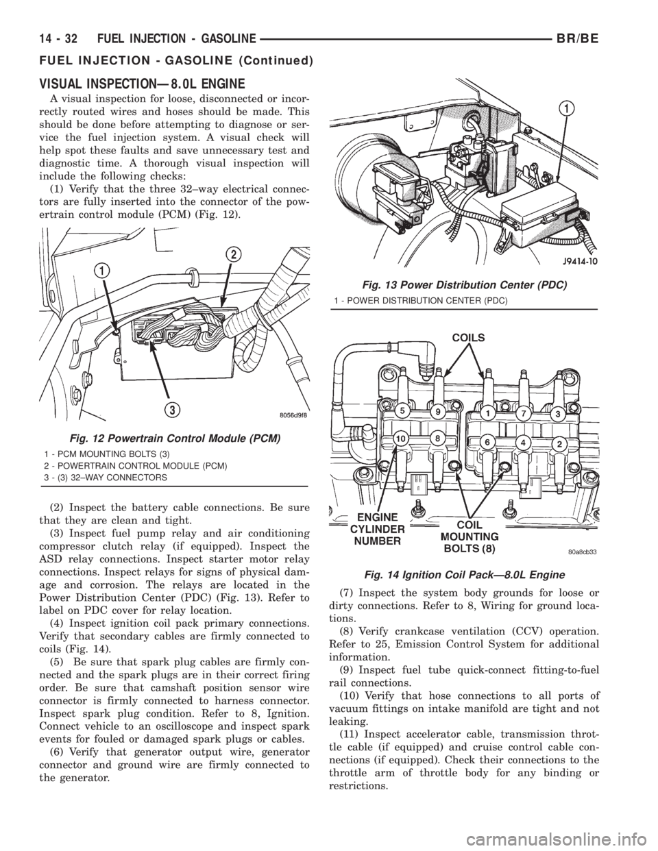
(1) Verify that the three 32±way electrical connec-
tors are fully inserted into the connector of the pow-
ertrain control module (PCM) (Fig. 12).
(2) Inspect the battery cable connections. Be sure
that they are clean and tight.
(3) Inspect fuel pump relay and air conditioning
compressor clutch relay (if equipped). Inspect the
ASD relay connections. Inspect starter motor relay
connections. Inspect relays for signs of physical dam-
age and corrosion. The relays are located in the
Power Distribution Center (PDC) (Fig. 13). Refer to
label on PDC cover for relay location.
(4) Inspect ignition coil pack primary connections.
Verify that secondary cables are firmly connected to
coils (Fig. 14).
(5) Be sure that spark plug cables are firmly con-
nected and the spark plugs are in their correct firing
order. Be sure that camshaft position sensor wire
connector is firmly connected to harness connector.
Inspect spark plug condition. Refer to 8, Ignition.
Connect vehicle to an oscilloscope and inspect spark
events for fouled or damaged spark plugs or cables.
(6) Verify that generator output wire, generator
connector and ground wire are firmly connected to
the generator.(7) Inspect the system body grounds for loose or
dirty connections. Refer to 8, Wiring for ground loca-
tions.
(8) Verify crankcase ventilation (CCV) operation.
Refer to 25, Emission Control System for additional
information.
(9) Inspect fuel tube quick-connect fitting-to-fuel
rail connections.
(10) Verify that hose connections to all ports of
vacuum fittings on intake manifold are tight and not
leaking.
(11) Inspect accelerator cable, transmission throt-
tle cable (if equipped) and cruise control cable con-
nections (if equipped). Check their connections to the
throttle arm of throttle body for any binding or
restrictions.
Fig. 12 Powertrain Control Module (PCM)
1 - PCM MOUNTING BOLTS (3)
2 - POWERTRAIN CONTROL MODULE (PCM)
3 - (3) 32±WAY CONNECTORS
Fig. 13 Power Distribution Center (PDC)
1 - POWER DISTRIBUTION CENTER (PDC)
Fig. 14 Ignition Coil PackÐ8.0L Engine
14 - 32 FUEL INJECTION - GASOLINEBR/BE
FUEL INJECTION - GASOLINE (Continued)
Page 1528 of 2889
(5) Install new plastic tie strap (Fig. 28) to secure
sensor pigtail harness to side of engine block. Thread
tie strap through casting hole on cylinder block.
FUEL PUMP RELAY
DESCRIPTION
The 5±pin, 12±volt, fuel pump relay is located in
the Power Distribution Center (PDC). Refer to the
label on the PDC cover for relay location.
OPERATION
The Powertrain Control Module (PCM) energizes
the electric fuel pump through the fuel pump relay.
The fuel pump relay is energized by first applying
battery voltage to it when the ignition key is turned
ON, and then applying a ground signal to the relay
from the PCM.
Whenever the ignition key is turned ON, the elec-
tric fuel pump will operate. But, the PCM will shut-
down the ground circuit to the fuel pump relay in
approximately 1±3 seconds unless the engine is oper-
ating or the starter motor is engaged.
REMOVAL
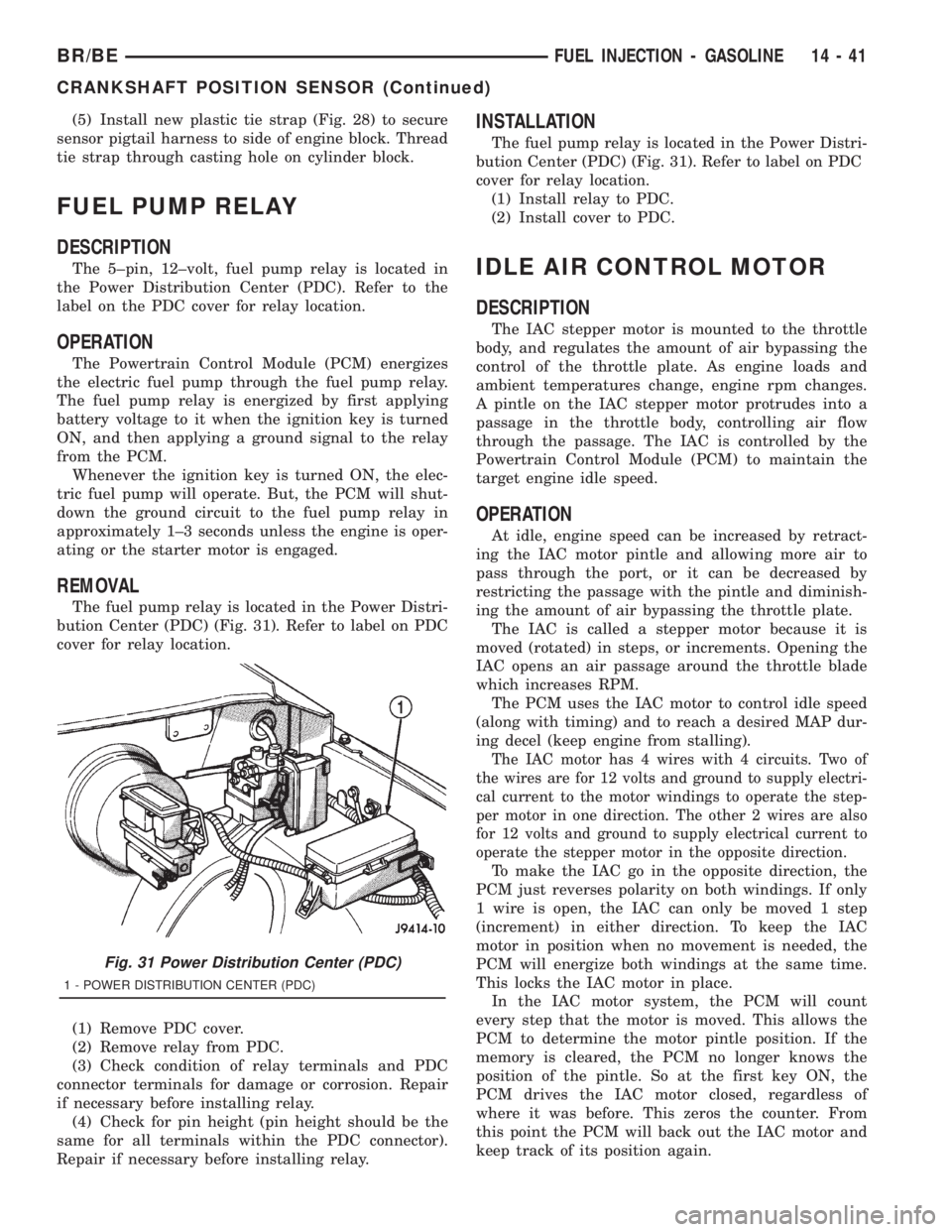
The fuel pump relay is located in the Power Distri-
bution Center (PDC) (Fig. 31). Refer to label on PDC
cover for relay location.
(1) Remove PDC cover.
(2) Remove relay from PDC.
(3) Check condition of relay terminals and PDC
connector terminals for damage or corrosion. Repair
if necessary before installing relay.
(4) Check for pin height (pin height should be the
same for all terminals within the PDC connector).
Repair if necessary before installing relay.
INSTALLATION
The fuel pump relay is located in the Power Distri-
bution Center (PDC) (Fig. 31). Refer to label on PDC
cover for relay location.
(1) Install relay to PDC.
(2) Install cover to PDC.
IDLE AIR CONTROL MOTOR
DESCRIPTION
The IAC stepper motor is mounted to the throttle
body, and regulates the amount of air bypassing the
control of the throttle plate. As engine loads and
ambient temperatures change, engine rpm changes.
A pintle on the IAC stepper motor protrudes into a
passage in the throttle body, controlling air flow
through the passage. The IAC is controlled by the
Powertrain Control Module (PCM) to maintain the
target engine idle speed.
OPERATION
At idle, engine speed can be increased by retract-
ing the IAC motor pintle and allowing more air to
pass through the port, or it can be decreased by
restricting the passage with the pintle and diminish-
ing the amount of air bypassing the throttle plate.
The IAC is called a stepper motor because it is
moved (rotated) in steps, or increments. Opening the
IAC opens an air passage around the throttle blade
which increases RPM.
The PCM uses the IAC motor to control idle speed
(along with timing) and to reach a desired MAP dur-
ing decel (keep engine from stalling).
The IAC motor has 4 wires with 4 circuits. Two of
the wires are for 12 volts and ground to supply electri-
cal current to the motor windings to operate the step-
per motor in one direction. The other 2 wires are also
for 12 volts and ground to supply electrical current to
operate the stepper motor in the opposite direction.
To make the IAC go in the opposite direction, the
PCM just reverses polarity on both windings. If only
1 wire is open, the IAC can only be moved 1 step
(increment) in either direction. To keep the IAC
motor in position when no movement is needed, the
PCM will energize both windings at the same time.
This locks the IAC motor in place.
In the IAC motor system, the PCM will count
every step that the motor is moved. This allows the
PCM to determine the motor pintle position. If the
memory is cleared, the PCM no longer knows the
position of the pintle. So at the first key ON, the
PCM drives the IAC motor closed, regardless of
where it was before. This zeros the counter. From
this point the PCM will back out the IAC motor and
keep track of its position again.
Fig. 31 Power Distribution Center (PDC)
1 - POWER DISTRIBUTION CENTER (PDC)
BR/BEFUEL INJECTION - GASOLINE 14 - 41
CRANKSHAFT POSITION SENSOR (Continued)
Page 1541 of 2889
FUEL DELIVERY - DIESEL
TABLE OF CONTENTS
page page
FUEL DELIVERY - DIESEL
DESCRIPTION...........................54
OPERATION.............................56
DIAGNOSIS AND TESTING.................56
AIR IN FUEL SYSTEM...................56
FUEL SUPPLY RESTRICTIONS............56
STANDARD PROCEDURE..................56
WATER DRAINING AT FUEL FILTER........56
CLEANING FUEL SYSTEM PARTS..........57
AIR BLEED............................57
SPECIFICATIONS........................58
SPECIAL TOOLS.........................59
FUEL FILTER / WATER SEPARATOR
DESCRIPTION...........................59
OPERATION.............................59
REMOVAL..............................60
INSTALLATION...........................61
FUEL HEATER
DESCRIPTION...........................62
OPERATION.............................62
DIAGNOSIS AND TESTING.................62
FUEL HEATER.........................62
REMOVAL..............................63
FUEL HEATER RELAY
DESCRIPTION...........................63
OPERATION.............................63
DIAGNOSIS AND TESTING.................64
FUEL HEATER RELAY...................64
REMOVAL..............................65
INSTALLATION...........................65
FUEL INJECTION PUMP
DESCRIPTION...........................65
OPERATION.............................66
DIAGNOSIS AND TESTING.................66
FUEL INJECTION PUMP TIMING...........66
REMOVAL..............................68
INSTALLATION...........................71
FUEL INJECTION PUMP DATA PLATE
SPECIFICATIONS........................73FUEL LEVEL SENDING UNIT / SENSOR
DESCRIPTION...........................73
OPERATION.............................73
FUEL LINES
DESCRIPTION...........................73
OPERATION.............................74
DIAGNOSIS AND TESTING.................74
HIGH-PRESSURE FUEL LINE LEAK.........74
REMOVAL..............................75
INSTALLATION...........................77
FUEL TANK
DESCRIPTION...........................78
FUEL TANK MODULE
DESCRIPTION...........................78
OPERATION.............................78
REMOVAL..............................78
INSTALLATION...........................79
FUEL TRANSFER PUMP
DESCRIPTION...........................79
OPERATION.............................79
DIAGNOSIS AND TESTING.................80
FUEL TRANSFER PUMP PRESSURE........80
REMOVAL..............................83
INSTALLATION...........................83
OVERFLOW VALVE
DESCRIPTION...........................83
OPERATION.............................83
DIAGNOSIS AND TESTING.................84
OVERFLOW VALVE.....................84
REMOVAL..............................84
INSTALLATION...........................85
WATER IN FUEL SENSOR
DESCRIPTION...........................85
OPERATION.............................85
REMOVAL..............................85
FUEL DRAIN MANIFOLD
DESCRIPTION...........................86
OPERATION.............................86
REMOVAL..............................86
INSTALLATION...........................86
FUEL DELIVERY - DIESEL
DESCRIPTION - DIESEL FUEL DELIVERY
SYSTEM
The fuel system on the Cummins 24 valveÐTurbo
Diesel Engine uses anelectronicfuel injection
pump with three control modules.Also refer to the Powertrain Control Module (PCM)
or Engine Control Module sections.
Some fuel system components are shown in (Fig.
1).
The fuel delivery system consists of the:
²Accelerator pedal
²Air cleaner housing/element
²Fuel drain manifold (passage)
14 - 54 FUEL DELIVERY - DIESELBR/BE