2001 DODGE RAM Fuel pump relay
[x] Cancel search: Fuel pump relayPage 2788 of 2889
EMISSIONS CONTROL
TABLE OF CONTENTS
page page
EMISSIONS CONTROL
DESCRIPTION............................1
OPERATION.............................18AIR INJECTION..........................25
EVAPORATIVE EMISSIONS.................31
EMISSIONS CONTROL
DESCRIPTION - DIESEL
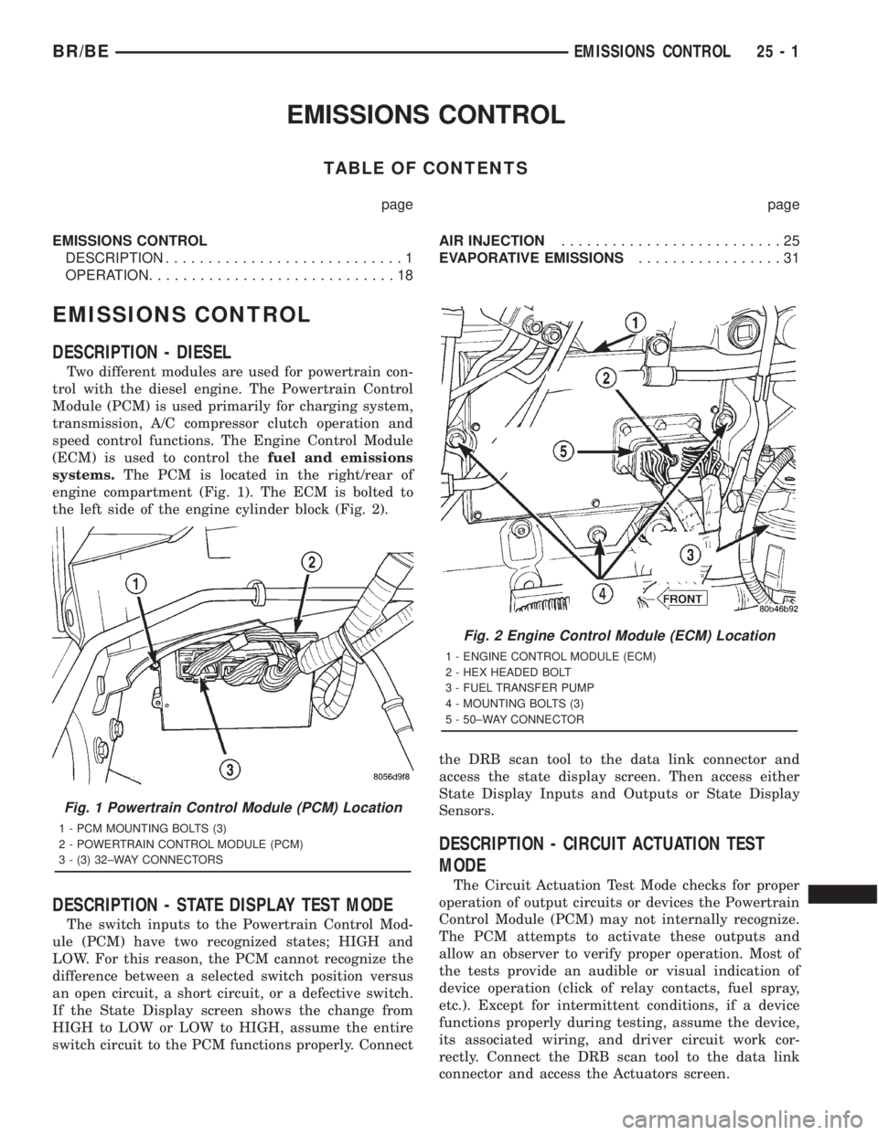
Two different modules are used for powertrain con-
trol with the diesel engine. The Powertrain Control
Module (PCM) is used primarily for charging system,
transmission, A/C compressor clutch operation and
speed control functions. The Engine Control Module
(ECM) is used to control thefuel and emissions
systems.The PCM is located in the right/rear of
engine compartment (Fig. 1). The ECM is bolted to
the left side of the engine cylinder block (Fig. 2).
DESCRIPTION - STATE DISPLAY TEST MODE
The switch inputs to the Powertrain Control Mod-
ule (PCM) have two recognized states; HIGH and
LOW. For this reason, the PCM cannot recognize the
difference between a selected switch position versus
an open circuit, a short circuit, or a defective switch.
If the State Display screen shows the change from
HIGH to LOW or LOW to HIGH, assume the entire
switch circuit to the PCM functions properly. Connectthe DRB scan tool to the data link connector and
access the state display screen. Then access either
State Display Inputs and Outputs or State Display
Sensors.
DESCRIPTION - CIRCUIT ACTUATION TEST
MODE
The Circuit Actuation Test Mode checks for proper
operation of output circuits or devices the Powertrain
Control Module (PCM) may not internally recognize.
The PCM attempts to activate these outputs and
allow an observer to verify proper operation. Most of
the tests provide an audible or visual indication of
device operation (click of relay contacts, fuel spray,
etc.). Except for intermittent conditions, if a device
functions properly during testing, assume the device,
its associated wiring, and driver circuit work cor-
rectly. Connect the DRB scan tool to the data link
connector and access the Actuators screen.
Fig. 1 Powertrain Control Module (PCM) Location
1 - PCM MOUNTING BOLTS (3)
2 - POWERTRAIN CONTROL MODULE (PCM)
3 - (3) 32±WAY CONNECTORS
Fig. 2 Engine Control Module (ECM) Location
1 - ENGINE CONTROL MODULE (ECM)
2 - HEX HEADED BOLT
3 - FUEL TRANSFER PUMP
4 - MOUNTING BOLTS (3)
5 - 50±WAY CONNECTOR
BR/BEEMISSIONS CONTROL 25 - 1
Page 2792 of 2889
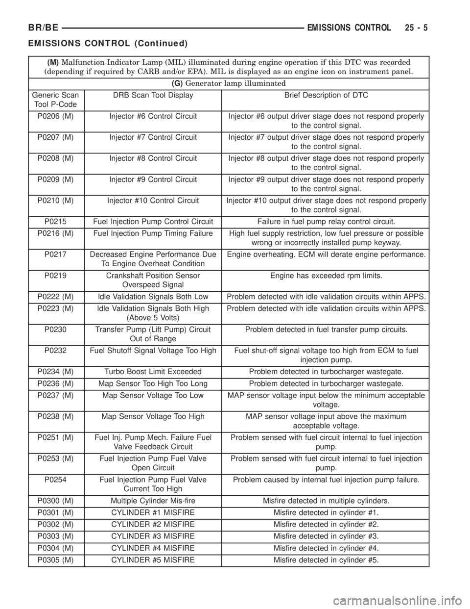
(M)Malfunction Indicator Lamp (MIL) illuminated during engine operation if this DTC was recorded
(depending if required by CARB and/or EPA). MIL is displayed as an engine icon on instrument panel.
(G)Generator lamp illuminated
Generic Scan
Tool P-CodeDRB Scan Tool Display Brief Description of DTC
P0206 (M) Injector #6 Control Circuit Injector #6 output driver stage does not respond properly
to the control signal.
P0207 (M) Injector #7 Control Circuit Injector #7 output driver stage does not respond properly
to the control signal.
P0208 (M) Injector #8 Control Circuit Injector #8 output driver stage does not respond properly
to the control signal.
P0209 (M) Injector #9 Control Circuit Injector #9 output driver stage does not respond properly
to the control signal.
P0210 (M) Injector #10 Control Circuit Injector #10 output driver stage does not respond properly
to the control signal.
P0215 Fuel Injection Pump Control Circuit Failure in fuel pump relay control circuit.
P0216 (M) Fuel Injection Pump Timing Failure High fuel supply restriction, low fuel pressure or possible
wrong or incorrectly installed pump keyway.
P0217 Decreased Engine Performance Due
To Engine Overheat ConditionEngine overheating. ECM will derate engine performance.
P0219 Crankshaft Position Sensor
Overspeed SignalEngine has exceeded rpm limits.
P0222 (M) Idle Validation Signals Both Low Problem detected with idle validation circuits within APPS.
P0223 (M) Idle Validation Signals Both High
(Above 5 Volts)Problem detected with idle validation circuits within APPS.
P0230 Transfer Pump (Lift Pump) Circuit
Out of RangeProblem detected in fuel transfer pump circuits.
P0232 Fuel Shutoff Signal Voltage Too High Fuel shut-off signal voltage too high from ECM to fuel
injection pump.
P0234 (M) Turbo Boost Limit Exceeded Problem detected in turbocharger wastegate.
P0236 (M) Map Sensor Too High Too Long Problem detected in turbocharger wastegate.
P0237 (M) Map Sensor Voltage Too Low MAP sensor voltage input below the minimum acceptable
voltage.
P0238 (M) Map Sensor Voltage Too High MAP sensor voltage input above the maximum
acceptable voltage.
P0251 (M) Fuel Inj. Pump Mech. Failure Fuel
Valve Feedback CircuitProblem sensed with fuel circuit internal to fuel injection
pump.
P0253 (M) Fuel Injection Pump Fuel Valve
Open CircuitProblem sensed with fuel circuit internal to fuel injection
pump.
P0254 Fuel Injection Pump Fuel Valve
Current Too HighProblem caused by internal fuel injection pump failure.
P0300 (M) Multiple Cylinder Mis-fire Misfire detected in multiple cylinders.
P0301 (M) CYLINDER #1 MISFIRE Misfire detected in cylinder #1.
P0302 (M) CYLINDER #2 MISFIRE Misfire detected in cylinder #2.
P0303 (M) CYLINDER #3 MISFIRE Misfire detected in cylinder #3.
P0304 (M) CYLINDER #4 MISFIRE Misfire detected in cylinder #4.
P0305 (M) CYLINDER #5 MISFIRE Misfire detected in cylinder #5.
BR/BEEMISSIONS CONTROL 25 - 5
EMISSIONS CONTROL (Continued)
Page 2793 of 2889
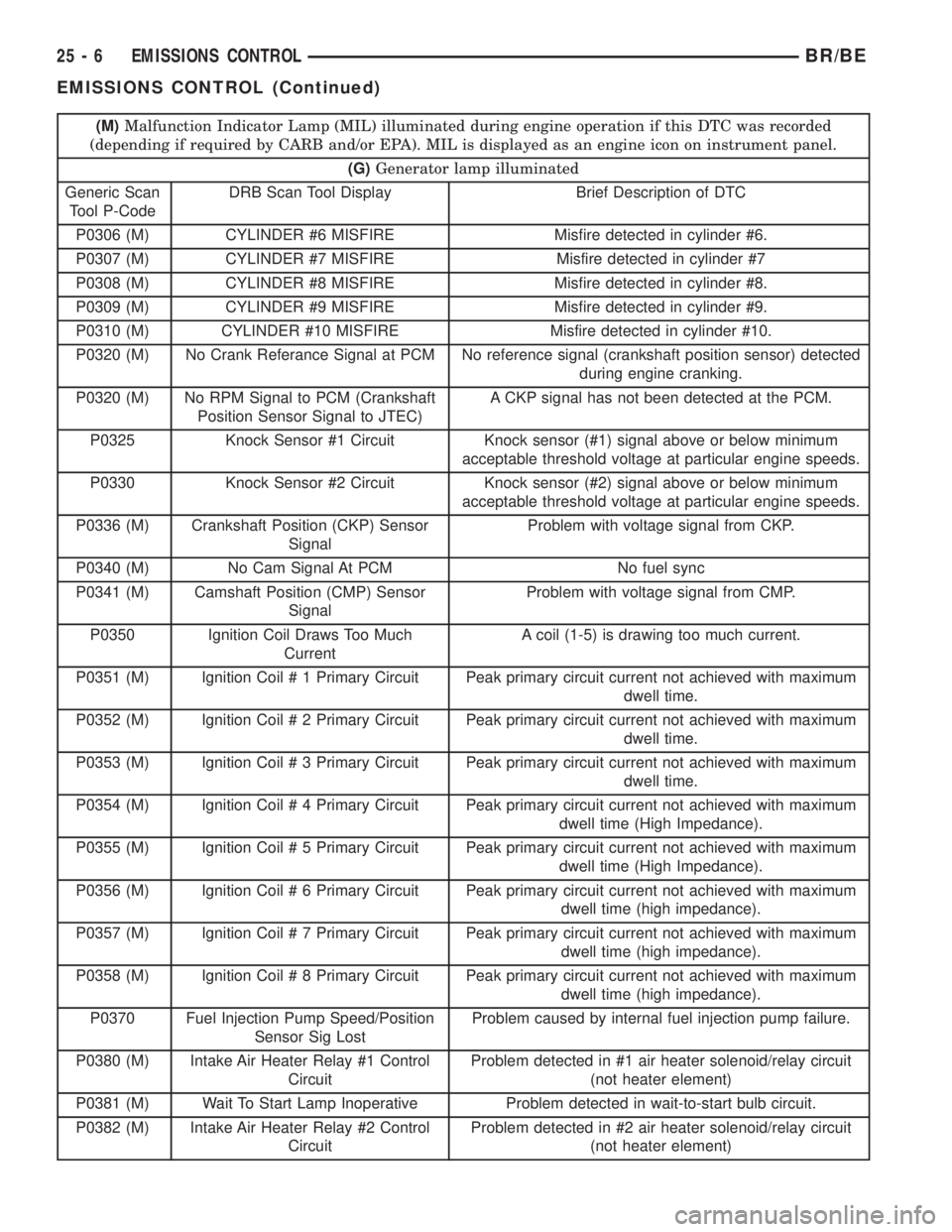
(M)Malfunction Indicator Lamp (MIL) illuminated during engine operation if this DTC was recorded
(depending if required by CARB and/or EPA). MIL is displayed as an engine icon on instrument panel.
(G)Generator lamp illuminated
Generic Scan
Tool P-CodeDRB Scan Tool Display Brief Description of DTC
P0306 (M) CYLINDER #6 MISFIRE Misfire detected in cylinder #6.
P0307 (M) CYLINDER #7 MISFIRE Misfire detected in cylinder #7
P0308 (M) CYLINDER #8 MISFIRE Misfire detected in cylinder #8.
P0309 (M) CYLINDER #9 MISFIRE Misfire detected in cylinder #9.
P0310 (M) CYLINDER #10 MISFIRE Misfire detected in cylinder #10.
P0320 (M) No Crank Referance Signal at PCM No reference signal (crankshaft position sensor) detected
during engine cranking.
P0320 (M) No RPM Signal to PCM (Crankshaft
Position Sensor Signal to JTEC)A CKP signal has not been detected at the PCM.
P0325 Knock Sensor #1 Circuit Knock sensor (#1) signal above or below minimum
acceptable threshold voltage at particular engine speeds.
P0330 Knock Sensor #2 Circuit Knock sensor (#2) signal above or below minimum
acceptable threshold voltage at particular engine speeds.
P0336 (M) Crankshaft Position (CKP) Sensor
SignalProblem with voltage signal from CKP.
P0340 (M) No Cam Signal At PCM No fuel sync
P0341 (M) Camshaft Position (CMP) Sensor
SignalProblem with voltage signal from CMP.
P0350 Ignition Coil Draws Too Much
CurrentA coil (1-5) is drawing too much current.
P0351 (M) Ignition Coil # 1 Primary Circuit Peak primary circuit current not achieved with maximum
dwell time.
P0352 (M) Ignition Coil # 2 Primary Circuit Peak primary circuit current not achieved with maximum
dwell time.
P0353 (M) Ignition Coil # 3 Primary Circuit Peak primary circuit current not achieved with maximum
dwell time.
P0354 (M) Ignition Coil # 4 Primary Circuit Peak primary circuit current not achieved with maximum
dwell time (High Impedance).
P0355 (M) Ignition Coil # 5 Primary Circuit Peak primary circuit current not achieved with maximum
dwell time (High Impedance).
P0356 (M) Ignition Coil # 6 Primary Circuit Peak primary circuit current not achieved with maximum
dwell time (high impedance).
P0357 (M) Ignition Coil # 7 Primary Circuit Peak primary circuit current not achieved with maximum
dwell time (high impedance).
P0358 (M) Ignition Coil # 8 Primary Circuit Peak primary circuit current not achieved with maximum
dwell time (high impedance).
P0370 Fuel Injection Pump Speed/Position
Sensor Sig LostProblem caused by internal fuel injection pump failure.
P0380 (M) Intake Air Heater Relay #1 Control
CircuitProblem detected in #1 air heater solenoid/relay circuit
(not heater element)
P0381 (M) Wait To Start Lamp Inoperative Problem detected in wait-to-start bulb circuit.
P0382 (M) Intake Air Heater Relay #2 Control
CircuitProblem detected in #2 air heater solenoid/relay circuit
(not heater element)
25 - 6 EMISSIONS CONTROLBR/BE
EMISSIONS CONTROL (Continued)
Page 2796 of 2889
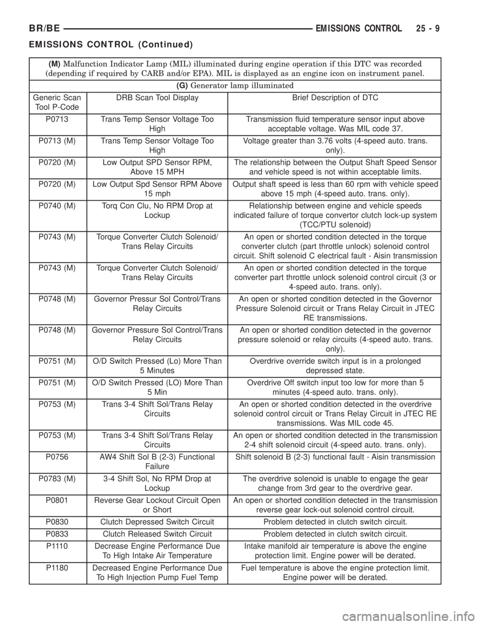
(M)Malfunction Indicator Lamp (MIL) illuminated during engine operation if this DTC was recorded
(depending if required by CARB and/or EPA). MIL is displayed as an engine icon on instrument panel.
(G)Generator lamp illuminated
Generic Scan
Tool P-CodeDRB Scan Tool Display Brief Description of DTC
P0713 Trans Temp Sensor Voltage Too
HighTransmission fluid temperature sensor input above
acceptable voltage. Was MIL code 37.
P0713 (M) Trans Temp Sensor Voltage Too
HighVoltage greater than 3.76 volts (4-speed auto. trans.
only).
P0720 (M) Low Output SPD Sensor RPM,
Above 15 MPHThe relationship between the Output Shaft Speed Sensor
and vehicle speed is not within acceptable limits.
P0720 (M) Low Output Spd Sensor RPM Above
15 mphOutput shaft speed is less than 60 rpm with vehicle speed
above 15 mph (4-speed auto. trans. only).
P0740 (M) Torq Con Clu, No RPM Drop at
LockupRelationship between engine and vehicle speeds
indicated failure of torque convertor clutch lock-up system
(TCC/PTU solenoid)
P0743 (M) Torque Converter Clutch Solenoid/
Trans Relay CircuitsAn open or shorted condition detected in the torque
converter clutch (part throttle unlock) solenoid control
circuit. Shift solenoid C electrical fault - Aisin transmission
P0743 (M) Torque Converter Clutch Solenoid/
Trans Relay CircuitsAn open or shorted condition detected in the torque
converter part throttle unlock solenoid control circuit (3 or
4-speed auto. trans. only).
P0748 (M) Governor Pressur Sol Control/Trans
Relay CircuitsAn open or shorted condition detected in the Governor
Pressure Solenoid circuit or Trans Relay Circuit in JTEC
RE transmissions.
P0748 (M) Governor Pressure Sol Control/Trans
Relay CircuitsAn open or shorted condition detected in the governor
pressure solenoid or relay circuits (4-speed auto. trans.
only).
P0751 (M) O/D Switch Pressed (Lo) More Than
5 MinutesOverdrive override switch input is in a prolonged
depressed state.
P0751 (M) O/D Switch Pressed (LO) More Than
5 MinOverdrive Off switch input too low for more than 5
minutes (4-speed auto. trans. only).
P0753 (M) Trans 3-4 Shift Sol/Trans Relay
CircuitsAn open or shorted condition detected in the overdrive
solenoid control circuit or Trans Relay Circuit in JTEC RE
transmissions. Was MIL code 45.
P0753 (M) Trans 3-4 Shift Sol/Trans Relay
CircuitsAn open or shorted condition detected in the transmission
2-4 shift solenoid circuit (4-speed auto. trans. only).
P0756 AW4 Shift Sol B (2-3) Functional
FailureShift solenoid B (2-3) functional fault - Aisin transmission
P0783 (M) 3-4 Shift Sol, No RPM Drop at
LockupThe overdrive solenoid is unable to engage the gear
change from 3rd gear to the overdrive gear.
P0801 Reverse Gear Lockout Circuit Open
or ShortAn open or shorted condition detected in the transmission
reverse gear lock-out solenoid control circuit.
P0830 Clutch Depressed Switch Circuit Problem detected in clutch switch circuit.
P0833 Clutch Released Switch Circuit Problem detected in clutch switch circuit.
P1110 Decrease Engine Performance Due
To High Intake Air TemperatureIntake manifold air temperature is above the engine
protection limit. Engine power will be derated.
P1180 Decreased Engine Performance Due
To High Injection Pump Fuel TempFuel temperature is above the engine protection limit.
Engine power will be derated.
BR/BEEMISSIONS CONTROL 25 - 9
EMISSIONS CONTROL (Continued)
Page 2797 of 2889
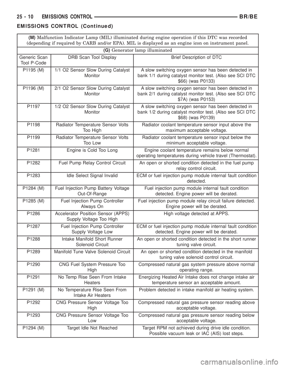
(M)Malfunction Indicator Lamp (MIL) illuminated during engine operation if this DTC was recorded
(depending if required by CARB and/or EPA). MIL is displayed as an engine icon on instrument panel.
(G)Generator lamp illuminated
Generic Scan
Tool P-CodeDRB Scan Tool Display Brief Description of DTC
P1195 (M) 1/1 O2 Sensor Slow During Catalyst
MonitorA slow switching oxygen sensor has been detected in
bank 1/1 during catalyst monitor test. (Also see SCI DTC
$66) (was P0133)
P1196 (M) 2/1 O2 Sensor Slow During Catalyst
MonitorA slow switching oxygen sensor has been detected in
bank 2/1 during catalyst monitor test. (Also see SCI DTC
$7A) (was P0153)
P1197 1/2 O2 Sensor Slow During Catalyst
MonitorA slow switching oxygen sensor has been detected in
bank 1/2 during catalyst monitor test. (Also see SCI DTC
$68) (was P0139)
P1198 Radiator Temperature Sensor Volts
Too HighRadiator coolant temperature sensor input above the
maximum acceptable voltage.
P1199 Radiator Temperature Sensor Volts
Too LowRadiator coolant temperature sensor input below the
minimum acceptable voltage.
P1281 Engine is Cold Too Long Engine coolant temperature remains below normal
operating temperatures during vehicle travel (Thermostat).
P1282 Fuel Pump Relay Control Circuit An open or shorted condition detected in the fuel pump
relay control circuit.
P1283 Idle Select Signal Invalid ECM or fuel injection pump module internal fault condition
detected.
P1284 (M) Fuel Injection Pump Battery Voltage
Out-Of-RangeFuel injection pump module internal fault condition
detected. Engine power will be derated.
P1285 (M) Fuel Injection Pump Controller
Always OnFuel injection pump module relay circuit failure detected.
Engine power will be derated.
P1286 Accelerator Position Sensor (APPS)
Supply Voltage Too HighHigh voltage detected at APPS.
P1287 Fuel Injection Pump Controller
Supply Voltage LowECM or fuel injection pump module internal fault condition
detected. Engine power will be derated.
P1288 Intake Manifold Short Runner
Solenoid CircuitAn open or shorted condition detected in the short runner
tuning valve circuit.
P1289 Manifold Tune Valve Solenoid Circuit An open or shorted condition detected in the manifold
tuning valve solenoid control circuit.
P1290 CNG Fuel System Pressure Too
HighCompressed natural gas system pressure above normal
operating range.
P1291 No Temp Rise Seen From Intake
HeatersEnergizing Heated Air Intake does not change intake air
temperature sensor an acceptable amount.
P1291 (M) No Temperature Rise Seen From
Intake Air HeatersProblem detected in intake manifold air heating system.
P1292 CNG Pressure Sensor Voltage Too
HighCompressed natural gas pressure sensor reading above
acceptable voltage.
P1293 CNG Pressure Sensor Voltage Too
LowCompressed natural gas pressure sensor reading below
acceptable voltage.
P1294 (M) Target Idle Not Reached Target RPM not achieved during drive idle condition.
Possible vacuum leak or IAC (AIS) lost steps.
25 - 10 EMISSIONS CONTROLBR/BE
EMISSIONS CONTROL (Continued)
Page 2800 of 2889
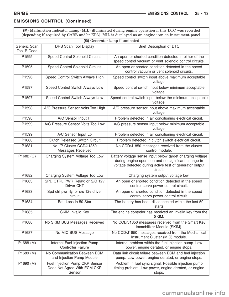
(M)Malfunction Indicator Lamp (MIL) illuminated during engine operation if this DTC was recorded
(depending if required by CARB and/or EPA). MIL is displayed as an engine icon on instrument panel.
(G)Generator lamp illuminated
Generic Scan
Tool P-CodeDRB Scan Tool Display Brief Description of DTC
P1595 Speed Control Solenoid Circuits An open or shorted condition detected in either of the
speed control vacuum or vent solenoid control circuits.
P1595 Speed Control Solenoid Circuits An open or shorted condition detected in the speed
control vacuum or vent solenoid circuits.
P1596 Speed Control Switch Always High Speed control switch input above maximum acceptable
voltage.
P1597 Speed Control Switch Always Low Speed control switch input below minimum acceptable
voltage.
P1597 Speed Control Switch Always Low Speed control switch input below the minimum acceptable
voltage.
P1598 A/C Pressure Sensor Volts Too High A/C pressure sensor input above maximum acceptable
voltage.
P1598 A/C Sensor Input Hi Problem detected in air conditioning electrical circuit.
P1599 A/C Pressure Sensor Volts Too Low A/C pressure sensor input below minimum acceptable
voltage.
P1599 A/C Sensor Input Lo Problem detected in air conditioning electrical circuit.
P1680 Clutch Released Switch Circuit Problem detected in clutch switch electrical circuit.
P1681 No I/P Cluster CCD/J1850
Messages ReceivedNo CCD/J1850 messages received from the cluster
control module.
P1682 (G) Charging System Voltage Too Low Battery voltage sense input below target charging voltage
during engine operation and no significant change in
voltage detected during active test of generator output
circuit.
P1682 Charging System Voltage Too Low Charging system output voltage low.
P1683 SPD CTRL PWR Relay; or S/C 12v
Driver CKTAn open or shorted condition detected in the speed
control servo power control circuit.
P1683 Spd ctrl pwr rly, or s/c 12v driver
circuitAn open or shorted condition detected in the speed
control servo power control circuit.
P1684 Batt Loss in 50 Star The battery has been disconnected within the last 50
starts
P1685 SKIM Invalid Key The engine controler has received an invalid key from the
SKIM.
P1686 No SKIM BUS Messages Received No CCD/J1850 messages received from the Smart Key
Immobilizer Module (SKIM).
P1687 No MIC BUS Message No CCD/J1850 messages received from the Mechanical
Instrument Cluster (MIC) module.
P1688 (M) Internal Fuel Injection Pump
Controller FailureInternal problem within the fuel injection pump. Low
power, engine derated, or engine stops.
P1689 (M) No Communication Between ECM
and Injection Pump ModuleData link circuit failure between ECM and fuel injection
pump. Low power, engine derated, or engine stops.
P1690 (M) Fuel Injection Pump CKP Sensor
Does Not Agree With ECM CKP
SensorProblem in fuel sync signal. Possible injection pump
timing problem. Low power, engine derated, or engine
stops.
BR/BEEMISSIONS CONTROL 25 - 13
EMISSIONS CONTROL (Continued)
Page 2802 of 2889
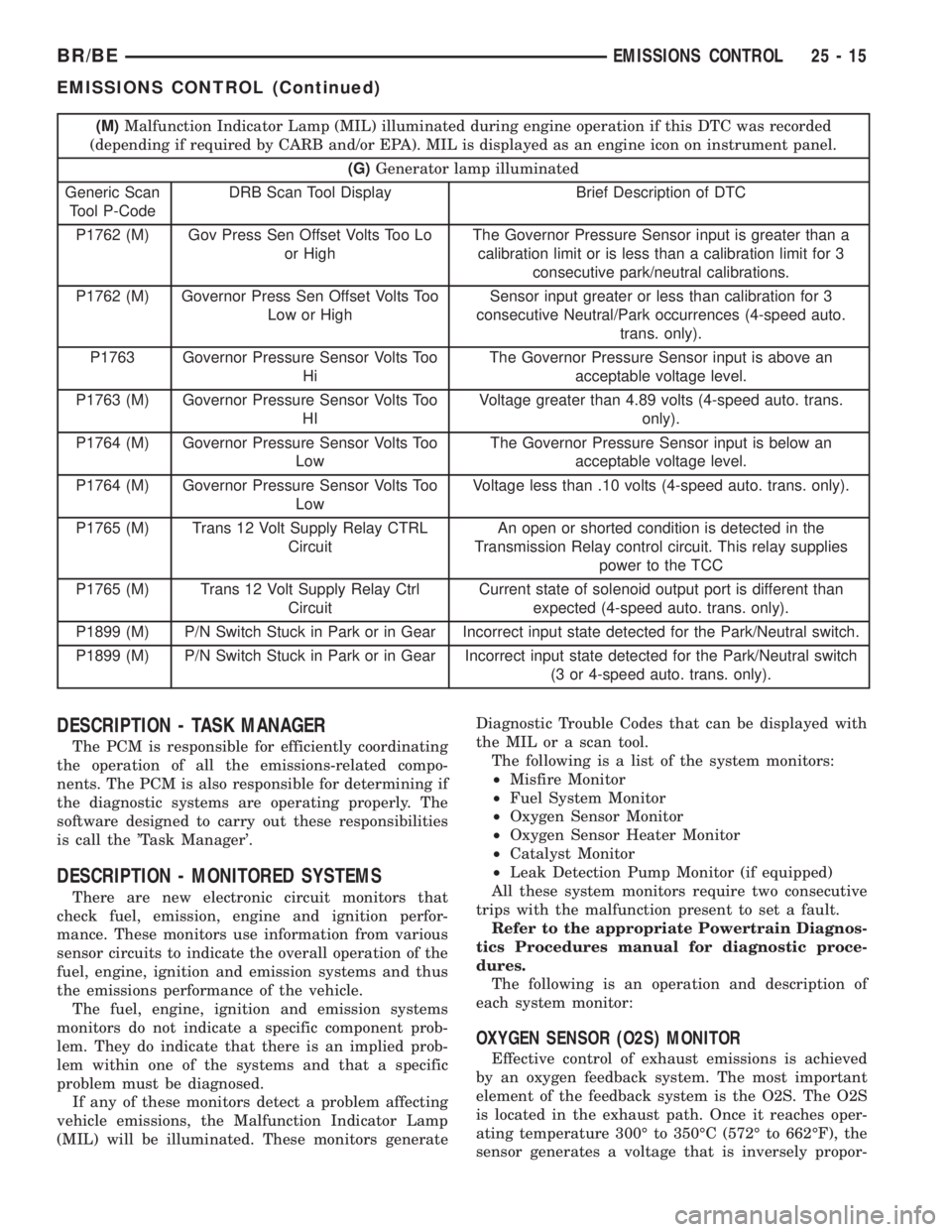
(M)Malfunction Indicator Lamp (MIL) illuminated during engine operation if this DTC was recorded
(depending if required by CARB and/or EPA). MIL is displayed as an engine icon on instrument panel.
(G)Generator lamp illuminated
Generic Scan
Tool P-CodeDRB Scan Tool Display Brief Description of DTC
P1762 (M) Gov Press Sen Offset Volts Too Lo
or HighThe Governor Pressure Sensor input is greater than a
calibration limit or is less than a calibration limit for 3
consecutive park/neutral calibrations.
P1762 (M) Governor Press Sen Offset Volts Too
Low or HighSensor input greater or less than calibration for 3
consecutive Neutral/Park occurrences (4-speed auto.
trans. only).
P1763 Governor Pressure Sensor Volts Too
HiThe Governor Pressure Sensor input is above an
acceptable voltage level.
P1763 (M) Governor Pressure Sensor Volts Too
HIVoltage greater than 4.89 volts (4-speed auto. trans.
only).
P1764 (M) Governor Pressure Sensor Volts Too
LowThe Governor Pressure Sensor input is below an
acceptable voltage level.
P1764 (M) Governor Pressure Sensor Volts Too
LowVoltage less than .10 volts (4-speed auto. trans. only).
P1765 (M) Trans 12 Volt Supply Relay CTRL
CircuitAn open or shorted condition is detected in the
Transmission Relay control circuit. This relay supplies
power to the TCC
P1765 (M) Trans 12 Volt Supply Relay Ctrl
CircuitCurrent state of solenoid output port is different than
expected (4-speed auto. trans. only).
P1899 (M) P/N Switch Stuck in Park or in Gear Incorrect input state detected for the Park/Neutral switch.
P1899 (M) P/N Switch Stuck in Park or in Gear Incorrect input state detected for the Park/Neutral switch
(3 or 4-speed auto. trans. only).
DESCRIPTION - TASK MANAGER
The PCM is responsible for efficiently coordinating
the operation of all the emissions-related compo-
nents. The PCM is also responsible for determining if
the diagnostic systems are operating properly. The
software designed to carry out these responsibilities
is call the 'Task Manager'.
DESCRIPTION - MONITORED SYSTEMS
There are new electronic circuit monitors that
check fuel, emission, engine and ignition perfor-
mance. These monitors use information from various
sensor circuits to indicate the overall operation of the
fuel, engine, ignition and emission systems and thus
the emissions performance of the vehicle.
The fuel, engine, ignition and emission systems
monitors do not indicate a specific component prob-
lem. They do indicate that there is an implied prob-
lem within one of the systems and that a specific
problem must be diagnosed.
If any of these monitors detect a problem affecting
vehicle emissions, the Malfunction Indicator Lamp
(MIL) will be illuminated. These monitors generateDiagnostic Trouble Codes that can be displayed with
the MIL or a scan tool.
The following is a list of the system monitors:
²Misfire Monitor
²Fuel System Monitor
²Oxygen Sensor Monitor
²Oxygen Sensor Heater Monitor
²Catalyst Monitor
²Leak Detection Pump Monitor (if equipped)
All these system monitors require two consecutive
trips with the malfunction present to set a fault.
Refer to the appropriate Powertrain Diagnos-
tics Procedures manual for diagnostic proce-
dures.
The following is an operation and description of
each system monitor:
OXYGEN SENSOR (O2S) MONITOR
Effective control of exhaust emissions is achieved
by an oxygen feedback system. The most important
element of the feedback system is the O2S. The O2S
is located in the exhaust path. Once it reaches oper-
ating temperature 300É to 350ÉC (572É to 662ÉF), the
sensor generates a voltage that is inversely propor-
BR/BEEMISSIONS CONTROL 25 - 15
EMISSIONS CONTROL (Continued)
Page 2848 of 2889
ABS INDICATOR - DESCRIPTION.........8J-14
ABS INDICATOR - OPERATION..........8J-14
A/C APPLICATION TABLE,
SPECIFICATIONS......................24-8
A/C COMPRESSOR - DESCRIPTION......24-46
A/C COMPRESSOR - DIAGNOSIS AND
TESTING...........................24-46
A/C COMPRESSOR - INSTALLATION......24-47
A/C COMPRESSOR - OPERATION........24-46
A/C COMPRESSOR - REMOVAL.........24-47
A/C COMPRESSOR CLUTCH -
DESCRIPTION.......................24-13
A/C COMPRESSOR CLUTCH -
INSPECTION........................24-16
A/C COMPRESSOR CLUTCH -
INSTALLATION.......................24-16
A/C COMPRESSOR CLUTCH -
OPERATION.........................24-13
A/C COMPRESSOR CLUTCH - REMOVAL . . 24-14
A/C COMPRESSOR CLUTCH BREAK-IN -
STANDARD PROCEDURE...............24-13
A/C COMPRESSOR CLUTCH COIL -
DIAGNOSIS AND TESTING.............24-13
A/C COMPRESSOR CLUTCH RELAY -
DESCRIPTION.......................24-17
A/C COMPRESSOR CLUTCH RELAY -
DIAGNOSIS AND TESTING.............24-17
A/C COMPRESSOR CLUTCH RELAY -
INSTALLATION.......................24-18
A/C COMPRESSOR CLUTCH RELAY -
OPERATION.........................24-17
A/C COMPRESSOR CLUTCH RELAY -
REMOVAL..........................24-18
A/C CONDENSER - DESCRIPTION........24-48
A/C CONDENSER - INSTALLATION.......24-49
A/C CONDENSER - OPERATION..........24-48
A/C CONDENSER - REMOVAL...........24-49
A/C EVAPORATOR - DESCRIPTION.......24-52
A/C EVAPORATOR - INSTALLATION......24-53
A/C EVAPORATOR - OPERATION.........24-53
A/C EVAPORATOR - REMOVAL..........24-53
A/C HEATER CONTROL - DESCRIPTION . . . 24-18
A/C HEATER CONTROL - DIAGNOSIS
AND TESTING.......................24-19
A/C HEATER CONTROL - INSTALLATION . . . 24-20
A/C HEATER CONTROL - OPERATION.....24-18
A/C HEATER CONTROL - REMOVAL......24-19
A/C HIGH PRESSURE SWITCH -
DESCRIPTION.......................24-20
A/C HIGH PRESSURE SWITCH -
DIAGNOSIS AND TESTING.............24-20
A/C HIGH PRESSURE SWITCH -
INSTALLATION.......................24-21
A/C HIGH PRESSURE SWITCH -
OPERATION.........................24-20
A/C HIGH PRESSURE SWITCH -
REMOVAL..........................24-21
A/C LINE COUPLERS - DESCRIPTION.....24-40
A/C LINE COUPLERS - OPERATION......24-41
A/C LINE COUPLERS - STANDARD
PROCEDURE........................24-43
A/C LOW PRESSURE SWITCH -
DESCRIPTION.......................24-21
A/C LOW PRESSURE SWITCH -
DIAGNOSIS AND TESTING.............24-21
A/C LOW PRESSURE SWITCH -
INSTALLATION.......................24-22
A/C LOW PRESSURE SWITCH -
OPERATION.........................24-21
A/C LOW PRESSURE SWITCH -
REMOVAL..........................24-21
A/C ORIFICE TUBE - DESCRIPTION.......24-53
A/C ORIFICE TUBE - OPERATION........24-53
A/C ORIFICE TUBE - REMOVAL..........24-54
A/C PERFORMANCE - DIAGNOSIS AND
TESTING............................24-2
ACCELERATOR PEDAL - INSTALLATION . . . 14-37
ACCELERATOR PEDAL - REMOVAL.......14-37
ACCELERATOR PEDAL POSITION
SENSOR - DESCRIPTION
...............14-91
ACCELERATOR PEDAL POSITION
SENSOR - INSTALLATION
..............14-93
ACCELERATOR PEDAL POSITION
SENSOR - OPERATION
................14-91
ACCELERATOR PEDAL POSITION
SENSOR - REMOVAL
..................14-91
ACCESSORY DRIVE BELT - DIAGNOSIS
AND TESTING
................7-24,7-27,7-31ACCUMULATOR - DESCRIPTION.........24-54
ACCUMULATOR - DESCRIPTION . 21-191,21-362,
21-537,21-707
ACCUMULATOR - INSPECTION . . 21-192,21-363,
21-538,21-708
ACCUMULATOR - INSTALLATION........24-55
ACCUMULATOR - OPERATION..........24-54
ACCUMULATOR - OPERATION . . . 21-191,21-362,
21-537,21-708
ACCUMULATOR - REMOVAL............24-54
ACTUATION TEST MODE - DESCRIPTION,
CIRCUIT.............................25-1
ACTUATOR - INSTALLATION, BLEND
DOOR.............................24-26
ACTUATOR - INSTALLATION, HEAT/
DEFROST DOOR.....................24-27
ACTUATOR - INSTALLATION, INSIDE
HANDLE.......................23-71,23-80
ACTUATOR - INSTALLATION, PANEL/
DEFROST DOOR.....................24-27
ACTUATOR - INSTALLATION,
RECIRCULATION DOOR................24-28
ACTUATOR - REMOVAL, BLEND DOOR....24-25
ACTUATOR - REMOVAL, HEAT/DEFROST
DOOR.............................24-26
ACTUATOR - REMOVAL, INSIDE HANDLE . 23-71,
23-80
ACTUATOR - REMOVAL, PANEL/DEFROST
DOOR.............................24-27
ACTUATOR - REMOVAL, RECIRCULATION
DOOR.............................24-27
ADAPTER - INSTALLATION, DEFROSTER
AND DEMISTER DUCT.................24-35
ADAPTER - REMOVAL, DEFROSTER AND
DEMISTER DUCT.....................24-35
ADAPTER BRACKET - INSTALLATION,
CAB CHASSIS........................13-9
ADAPTER BRACKET - REMOVAL, CAB
CHASSIS............................13-9
ADAPTER HOUSING SEAL -
INSTALLATION.................21-132,21-87
ADAPTER HOUSING SEAL - REMOVAL . . 21-132,
21-87
ADDING ADDITIONAL COOLANT -
STANDARD PROCEDURE................7-16
ADDITIONAL COOLANT - STANDARD
PROCEDURE, ADDING..................7-16
ADHESIVE LOCATIONS, SPECIFICATIONS
- STRUCTURAL......................23-44
ADJUSTER - DIAGNOSIS & TESTING,
POWER LUMBAR....................8N-18
ADJUSTER - INSTALLATION, SEAT BELT
TURNING LOOP.....................8O-29
ADJUSTER - INSTALLATION, SEAT
TRACK............................23-143
ADJUSTER - REMOVAL, SEAT BELT
TURNING LOOP.....................8O-29
ADJUSTER - REMOVAL, SEAT TRACK....23-143
ADJUSTER ASSEMBLY - INSTALLATION,
ROCKER ARM........................9-85
ADJUSTER ASSEMBLY - REMOVAL,
ROCKER ARM........................9-85
ADJUSTER ASSY - CLEANING, ROCKER
ARM ..............................9-262
ADJUSTER ASSY - DESCRIPTION,
ROCKER ARM.......................9-261
ADJUSTER ASSY - INSPECTION,
ROCKER ARM.......................9-262
ADJUSTER ASSY - INSTALLATION,
ROCKER ARM.............9-142,9-200,9-263
ADJUSTER ASSY - REMOVAL, ROCKER
ARM ....................9-142,9-200,9-261
ADJUSTER KNOB - INSTALLATION,
TURNING LOOP HEIGHT...............8O-30
ADJUSTER KNOB - REMOVAL, TURNING
LOOP HEIGHT.......................8O-30
ADJUSTMENT - STANDARD
PROCEDURE, COMPASS VARIATION......8M-4
ADJUSTMENT AND VERIFICATION -
STANDARD PROCEDURE, VALVE LASH....9-256
ADJUSTMENT, BANDS . . . 21-193,21-364,21-539,
21-709
ADJUSTMENT, CABLE TENSIONER
........5-40
ADJUSTMENT, CARGO DOOR
...........23-78
ADJUSTMENT, CENTER BEARING -
CENTER BEARING
.....................3-10
ADJUSTMENT, FRONT DOOR FORE/AFT
. . . 23-68
ADJUSTMENT, FRONT DOOR IN/OUT
.....23-69ADJUSTMENT, FRONT DOOR LATCH......23-72
ADJUSTMENT, FRONT DOOR UP/DOWN . . . 23-69
ADJUSTMENT, FRONT FASCIA...........13-2
ADJUSTMENT, HOOD................23-100
ADJUSTMENT, LATCH................23-100
ADJUSTMENT, LATCH STRIKER........23-102
ADJUSTMENT, REAR BRAKE DRUM.......5-34
ADJUSTMENT, SHIFT LEVER....21-853,21-888,
21-925
ADJUSTMENT, SHIFT MECHANISM.....21-252,
21-423,21-596,21-769
ADJUSTMENTS, FOG LAMP UNIT........8L-12
ADJUSTMENTS, FRONT AXLE - 216FBI....3-17
ADJUSTMENTS, FRONT AXLE - 248FBI....3-50
ADJUSTMENTS, GEAR.................19-16
ADJUSTMENTS, HEADLAMP UNIT.......8L-21
ADJUSTMENTS, REAR AXLE - 248RBI....3-114
ADJUSTMENTS, REAR AXLE - 267RBI....3-145
ADJUSTMENTS, REAR AXLE - 286RBI....3-174
ADJUSTMENTS, REAR AXLE - 9 1/4 .......3-84
ADJUSTMENTS, TRANSMISSION
THROTTLE VALVE CABLE . 21-254,21-425,21-598,
21-771
ADJUSTMENTS, VALVE BODY . . . 21-304,21-476,
21-646,21-818
AFTER AN AIRBAG DEPLOYMENT -
STANDARD PROCEDURE, SERVICE.......8O-4
AIR BLEED - STANDARD PROCEDURE....14-57
AIR CHECKING TRANSMISSION CLUTCH
AND BAND OPERATION - DIAGNOSIS
AND TESTING................21-147,21-318
AIR CLEANER ELEMENT - INSTALLATION . . 9-245
AIR CLEANER ELEMENT - REMOVAL.....9-244
AIR CONDITIONER - DESCRIPTION,
HEATER .............................24-1
AIR CONDITIONER - OPERATION,
HEATER .............................24-1
AIR CONDITIONING - INSTALLATION,
WATER PUMP BYPASS HOSE WITH.......7-77
AIR CONDITIONING - INSTALLATION,
WATER PUMP BYPASS HOSE
WITHOUT............................7-78
AIR CONDITIONING - REMOVAL, WATER
PUMP BYPASS HOSE WITH.............7-74
AIR CONDITIONING - REMOVAL, WATER
PUMP BYPASS HOSE WITHOUT..........7-77
AIR CONTROL MOTOR - DESCRIPTION,
IDLE...............................14-41
AIR CONTROL MOTOR - OPERATION,
IDLE...............................14-41
AIR COOLER AND PLUMBING -
CLEANING, CHARGE..................11-18
AIR COOLER AND PLUMBING -
DESCRIPTION, CHARGE...............11-17
AIR COOLER AND PLUMBING -
INSPECTION, CHARGE.................11-18
AIR COOLER AND PLUMBING -
INSTALLATION, CHARGE...............11-18
AIR COOLER AND PLUMBING -
OPERATION, CHARGE.................11-17
AIR COOLER AND PLUMBING -
REMOVAL, CHARGE..................11-17
AIR DAM - INSTALLATION, FRONT........13-2
AIR DAM - REMOVAL, FRONT...........13-1
AIR EXHAUSTER - INSTALLATION.......23-77
AIR EXHAUSTER - REMOVAL...........23-77
AIR HEATER - DESCRIPTION, INTAKE....14-100
AIR HEATER - INSTALLATION, INTAKE . . . 14-101
AIR HEATER - OPERATION, INTAKE.....14-100
AIR HEATER - REMOVAL, INTAKE.......14-100
AIR HEATER RELAY - DESCRIPTION,
INTAKE............................14-101
AIR HEATER RELAY - INSTALLATION,
INTAKE............................14-102
AIR HEATER RELAY - OPERATION,
INTAKE............................14-102
AIR HEATER RELAY - REMOVAL, INTAKE . 14-102
AIR IN FUEL SYSTEM - DIAGNOSIS AND
TESTING...........................14-56
AIR INJECTION PUMP - DESCRIPTION....25-28
AIR INJECTION PUMP - DIAGNOSIS AND
TESTING...........................25-28
AIR INJECTION PUMP - INSTALLATION . . . 25-29
AIR INJECTION PUMP - OPERATION
.....25-28
AIR INJECTION PUMP - REMOVAL
.......25-29
AIR INJECTION SYSTEM - DESCRIPTION
. . 25-25
AIR INJECTION SYSTEM - OPERATION
....25-27
AIR INJECTION SYSTEM - TORQUE
......25-28
BR/BEINDEX 1
Description Group-Page Description Group-Page Description Group-Page