2001 DODGE RAM service
[x] Cancel search: servicePage 2468 of 2889
Inspect rear extension bushing. Replace if worn or
scored.DRIVE CHAIN
Examine the drive chain and shaft bearings.
replace the chain if stretched, distorted, or if any of
the links bind. Replace the bearings if rough, or
noisy.
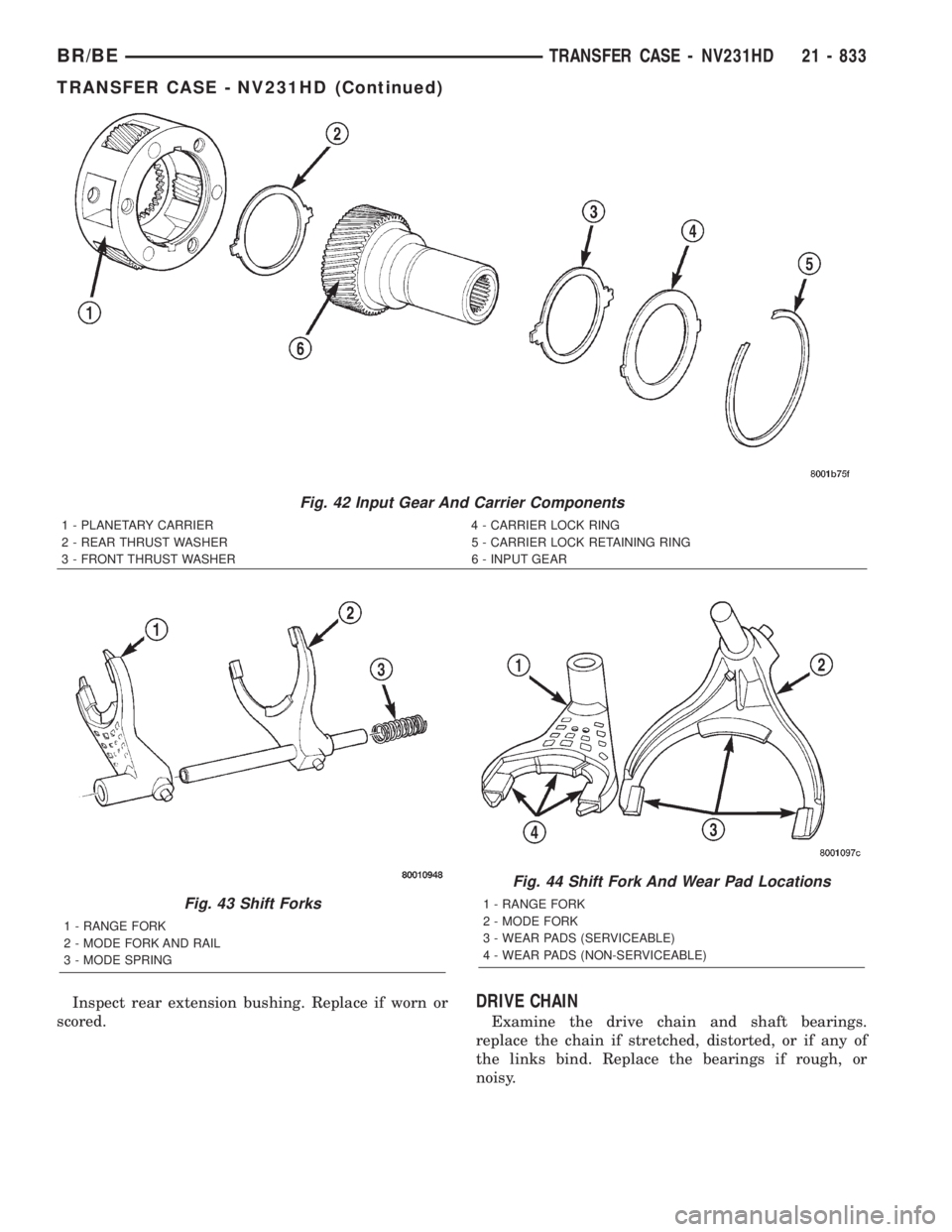
Fig. 42 Input Gear And Carrier Components
1 - PLANETARY CARRIER 4 - CARRIER LOCK RING
2 - REAR THRUST WASHER 5 - CARRIER LOCK RETAINING RING
3 - FRONT THRUST WASHER 6 - INPUT GEAR
Fig. 43 Shift Forks
1 - RANGE FORK
2 - MODE FORK AND RAIL
3 - MODE SPRING
Fig. 44 Shift Fork And Wear Pad Locations
1 - RANGE FORK
2 - MODE FORK
3 - WEAR PADS (SERVICEABLE)
4 - WEAR PADS (NON-SERVICEABLE)
BR/BETRANSFER CASE - NV231HD 21 - 833
TRANSFER CASE - NV231HD (Continued)
Page 2469 of 2889
LOW RANGE ANNULUS GEAR
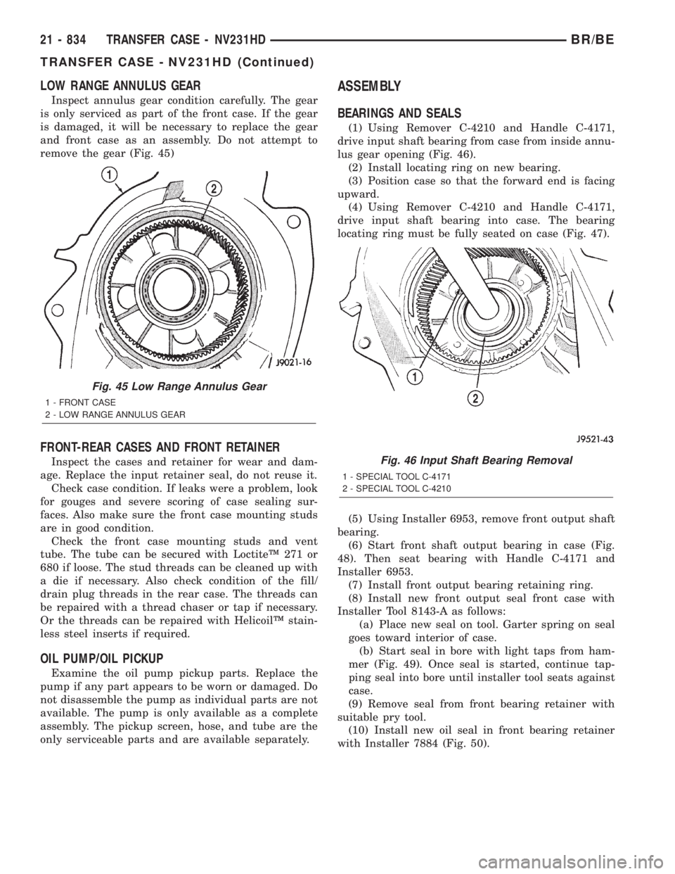
Inspect annulus gear condition carefully. The gear
is only serviced as part of the front case. If the gear
is damaged, it will be necessary to replace the gear
and front case as an assembly. Do not attempt to
remove the gear (Fig. 45)
FRONT-REAR CASES AND FRONT RETAINER
Inspect the cases and retainer for wear and dam-
age. Replace the input retainer seal, do not reuse it.
Check case condition. If leaks were a problem, look
for gouges and severe scoring of case sealing sur-
faces. Also make sure the front case mounting studs
are in good condition.
Check the front case mounting studs and vent
tube. The tube can be secured with LoctiteŸ 271 or
680 if loose. The stud threads can be cleaned up with
a die if necessary. Also check condition of the fill/
drain plug threads in the rear case. The threads can
be repaired with a thread chaser or tap if necessary.
Or the threads can be repaired with HelicoilŸ stain-
less steel inserts if required.
OIL PUMP/OIL PICKUP
Examine the oil pump pickup parts. Replace the
pump if any part appears to be worn or damaged. Do
not disassemble the pump as individual parts are not
available. The pump is only available as a complete
assembly. The pickup screen, hose, and tube are the
only serviceable parts and are available separately.
ASSEMBLY
BEARINGS AND SEALS
(1) Using Remover C-4210 and Handle C-4171,
drive input shaft bearing from case from inside annu-
lus gear opening (Fig. 46).
(2) Install locating ring on new bearing.
(3) Position case so that the forward end is facing
upward.
(4) Using Remover C-4210 and Handle C-4171,
drive input shaft bearing into case. The bearing
locating ring must be fully seated on case (Fig. 47).
(5) Using Installer 6953, remove front output shaft
bearing.
(6) Start front shaft output bearing in case (Fig.
48). Then seat bearing with Handle C-4171 and
Installer 6953.
(7) Install front output bearing retaining ring.
(8) Install new front output seal front case with
Installer Tool 8143-A as follows:
(a) Place new seal on tool. Garter spring on seal
goes toward interior of case.
(b) Start seal in bore with light taps from ham-
mer (Fig. 49). Once seal is started, continue tap-
ping seal into bore until installer tool seats against
case.
(9) Remove seal from front bearing retainer with
suitable pry tool.
(10) Install new oil seal in front bearing retainer
with Installer 7884 (Fig. 50).
Fig. 45 Low Range Annulus Gear
1 - FRONT CASE
2 - LOW RANGE ANNULUS GEAR
Fig. 46 Input Shaft Bearing Removal
1 - SPECIAL TOOL C-4171
2 - SPECIAL TOOL C-4210
21 - 834 TRANSFER CASE - NV231HDBR/BE
TRANSFER CASE - NV231HD (Continued)
Page 2503 of 2889
SHIFT FORKS/HUBS/SLEEVES
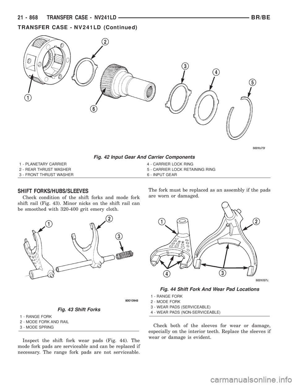
Check condition of the shift forks and mode fork
shift rail (Fig. 43). Minor nicks on the shift rail can
be smoothed with 320-400 grit emery cloth.
Inspect the shift fork wear pads (Fig. 44). The
mode fork pads are serviceable and can be replaced if
necessary. The range fork pads are not serviceable.The fork must be replaced as an assembly if the pads
are worn or damaged.
Check both of the sleeves for wear or damage,
especially on the interior teeth. Replace the sleeves if
wear or damage is evident.
Fig. 42 Input Gear And Carrier Components
1 - PLANETARY CARRIER 4 - CARRIER LOCK RING
2 - REAR THRUST WASHER 5 - CARRIER LOCK RETAINING RING
3 - FRONT THRUST WASHER 6 - INPUT GEAR
Fig. 43 Shift Forks
1 - RANGE FORK
2 - MODE FORK AND RAIL
3 - MODE SPRING
Fig. 44 Shift Fork And Wear Pad Locations
1 - RANGE FORK
2 - MODE FORK
3 - WEAR PADS (SERVICEABLE)
4 - WEAR PADS (NON-SERVICEABLE)
21 - 868 TRANSFER CASE - NV241LDBR/BE
TRANSFER CASE - NV241LD (Continued)
Page 2504 of 2889
REAR RETAINER COMPONENTS
Inspect the retainer components. Replace the bear-
ing if rough or noisy. Check the retainer for cracks or
wear in the bearing bore.
Inspect the retaining rings and washers. Replace
any part if distorted, bent, or broken. Reuse is not
recommended.
Inspect rear extension bushing. Replace if worn or
scored.
DRIVE CHAIN
Examine the drive chain and shaft bearings.
replace the chain if stretched, distorted, or if any of
the links bind. Replace the bearings if rough, or
noisy.
LOW RANGE ANNULUS GEAR
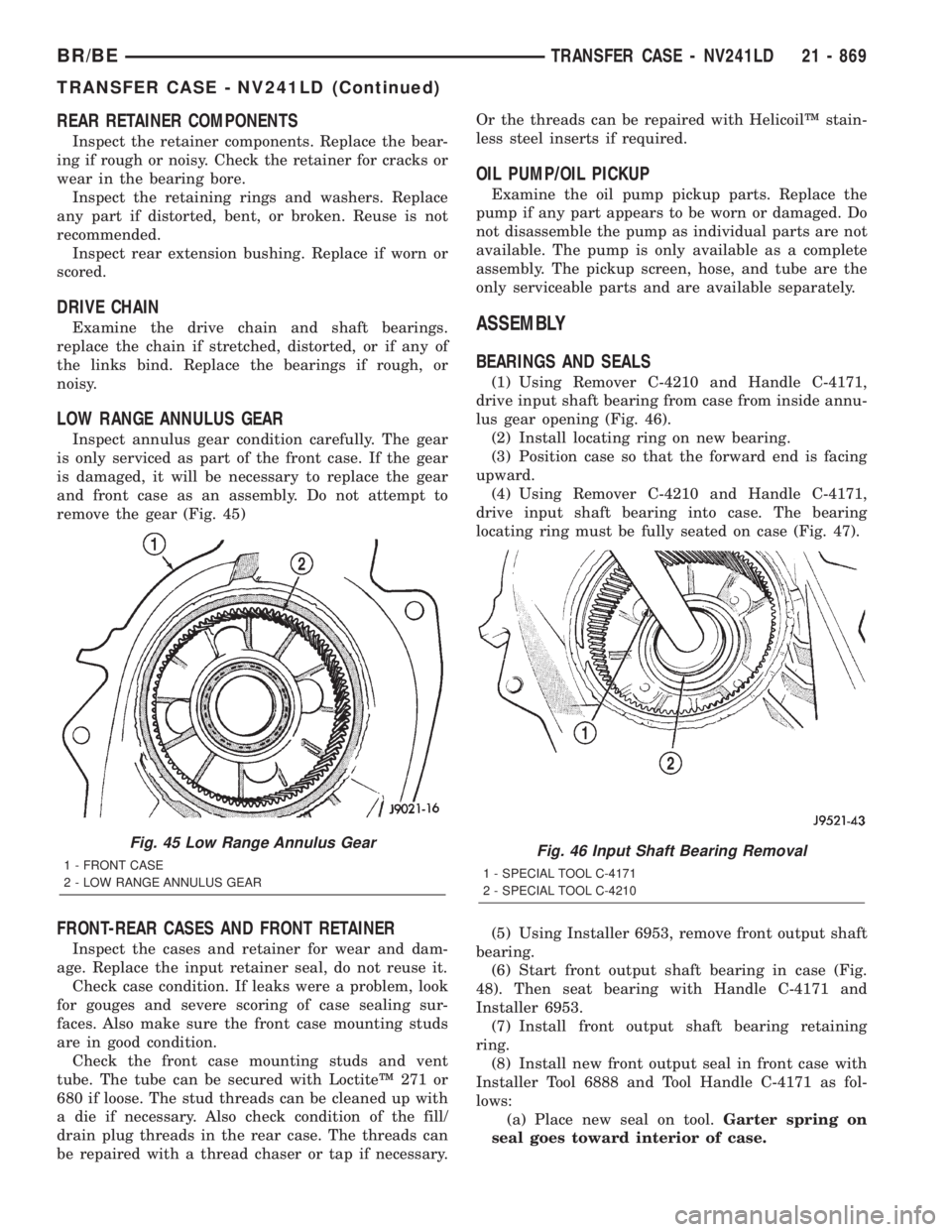
Inspect annulus gear condition carefully. The gear
is only serviced as part of the front case. If the gear
is damaged, it will be necessary to replace the gear
and front case as an assembly. Do not attempt to
remove the gear (Fig. 45)
FRONT-REAR CASES AND FRONT RETAINER
Inspect the cases and retainer for wear and dam-
age. Replace the input retainer seal, do not reuse it.
Check case condition. If leaks were a problem, look
for gouges and severe scoring of case sealing sur-
faces. Also make sure the front case mounting studs
are in good condition.
Check the front case mounting studs and vent
tube. The tube can be secured with LoctiteŸ 271 or
680 if loose. The stud threads can be cleaned up with
a die if necessary. Also check condition of the fill/
drain plug threads in the rear case. The threads can
be repaired with a thread chaser or tap if necessary.Or the threads can be repaired with HelicoilŸ stain-
less steel inserts if required.
OIL PUMP/OIL PICKUP
Examine the oil pump pickup parts. Replace the
pump if any part appears to be worn or damaged. Do
not disassemble the pump as individual parts are not
available. The pump is only available as a complete
assembly. The pickup screen, hose, and tube are the
only serviceable parts and are available separately.
ASSEMBLY
BEARINGS AND SEALS
(1) Using Remover C-4210 and Handle C-4171,
drive input shaft bearing from case from inside annu-
lus gear opening (Fig. 46).
(2) Install locating ring on new bearing.
(3) Position case so that the forward end is facing
upward.
(4) Using Remover C-4210 and Handle C-4171,
drive input shaft bearing into case. The bearing
locating ring must be fully seated on case (Fig. 47).
(5) Using Installer 6953, remove front output shaft
bearing.
(6) Start front output shaft bearing in case (Fig.
48). Then seat bearing with Handle C-4171 and
Installer 6953.
(7) Install front output shaft bearing retaining
ring.
(8) Install new front output seal in front case with
Installer Tool 6888 and Tool Handle C-4171 as fol-
lows:
(a) Place new seal on tool.Garter spring on
seal goes toward interior of case.
Fig. 45 Low Range Annulus Gear
1 - FRONT CASE
2 - LOW RANGE ANNULUS GEARFig. 46 Input Shaft Bearing Removal
1 - SPECIAL TOOL C-4171
2 - SPECIAL TOOL C-4210
BR/BETRANSFER CASE - NV241LD 21 - 869
TRANSFER CASE - NV241LD (Continued)
Page 2535 of 2889
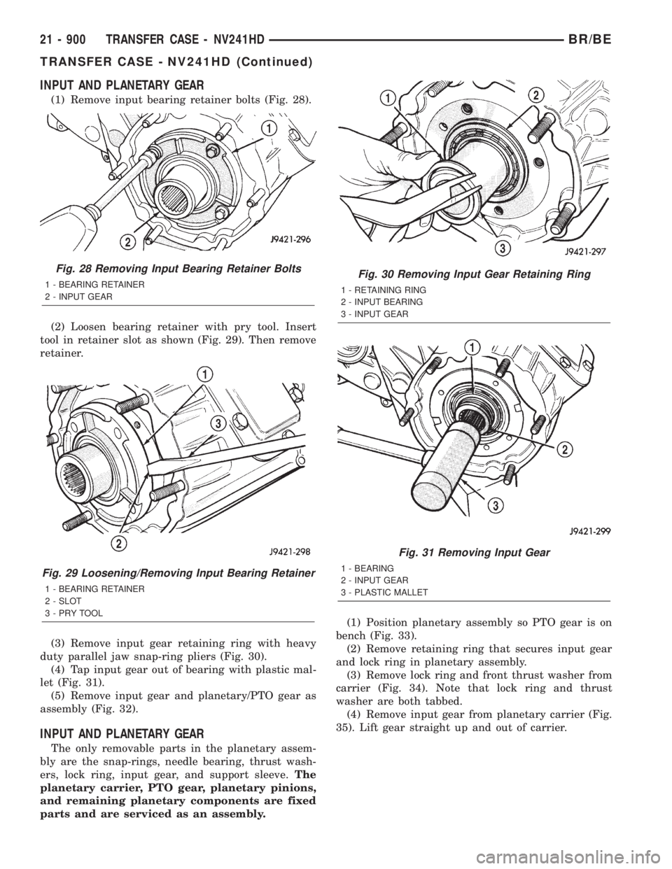
INPUT AND PLANETARY GEAR
(1) Remove input bearing retainer bolts (Fig. 28).
(2) Loosen bearing retainer with pry tool. Insert
tool in retainer slot as shown (Fig. 29). Then remove
retainer.
(3) Remove input gear retaining ring with heavy
duty parallel jaw snap-ring pliers (Fig. 30).
(4) Tap input gear out of bearing with plastic mal-
let (Fig. 31).
(5) Remove input gear and planetary/PTO gear as
assembly (Fig. 32).
INPUT AND PLANETARY GEAR
The only removable parts in the planetary assem-
bly are the snap-rings, needle bearing, thrust wash-
ers, lock ring, input gear, and support sleeve.The
planetary carrier, PTO gear, planetary pinions,
and remaining planetary components are fixed
parts and are serviced as an assembly.(1) Position planetary assembly so PTO gear is on
bench (Fig. 33).
(2) Remove retaining ring that secures input gear
and lock ring in planetary assembly.
(3) Remove lock ring and front thrust washer from
carrier (Fig. 34). Note that lock ring and thrust
washer are both tabbed.
(4) Remove input gear from planetary carrier (Fig.
35). Lift gear straight up and out of carrier.
Fig. 28 Removing Input Bearing Retainer Bolts
1 - BEARING RETAINER
2 - INPUT GEAR
Fig. 29 Loosening/Removing Input Bearing Retainer
1 - BEARING RETAINER
2 - SLOT
3-PRYTOOL
Fig. 30 Removing Input Gear Retaining Ring
1 - RETAINING RING
2 - INPUT BEARING
3 - INPUT GEAR
Fig. 31 Removing Input Gear
1 - BEARING
2 - INPUT GEAR
3 - PLASTIC MALLET
21 - 900 TRANSFER CASE - NV241HDBR/BE
TRANSFER CASE - NV241HD (Continued)
Page 2539 of 2889
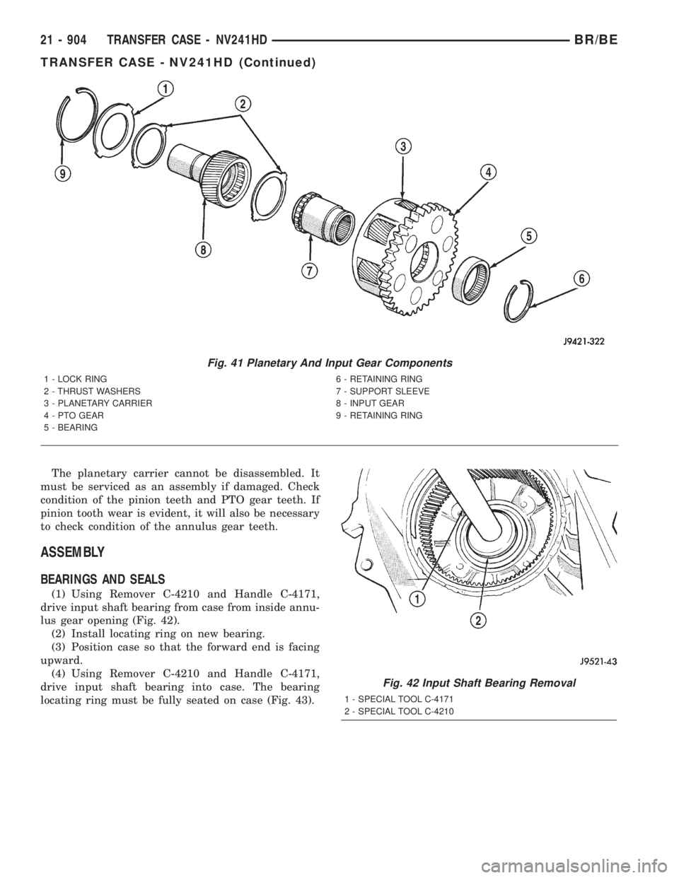
The planetary carrier cannot be disassembled. It
must be serviced as an assembly if damaged. Check
condition of the pinion teeth and PTO gear teeth. If
pinion tooth wear is evident, it will also be necessary
to check condition of the annulus gear teeth.
ASSEMBLY
BEARINGS AND SEALS
(1) Using Remover C-4210 and Handle C-4171,
drive input shaft bearing from case from inside annu-
lus gear opening (Fig. 42).
(2) Install locating ring on new bearing.
(3) Position case so that the forward end is facing
upward.
(4) Using Remover C-4210 and Handle C-4171,
drive input shaft bearing into case. The bearing
locating ring must be fully seated on case (Fig. 43).
Fig. 41 Planetary And Input Gear Components
1 - LOCK RING 6 - RETAINING RING
2 - THRUST WASHERS 7 - SUPPORT SLEEVE
3 - PLANETARY CARRIER 8 - INPUT GEAR
4 - PTO GEAR 9 - RETAINING RING
5 - BEARING
Fig. 42 Input Shaft Bearing Removal
1 - SPECIAL TOOL C-4171
2 - SPECIAL TOOL C-4210
21 - 904 TRANSFER CASE - NV241HDBR/BE
TRANSFER CASE - NV241HD (Continued)
Page 2563 of 2889
METHOD 2 (RELOCATE TIRE ON WHEEL)
NOTE: Rotating the tire on wheel is particularly
effective when there is runout in both tire and
wheel.
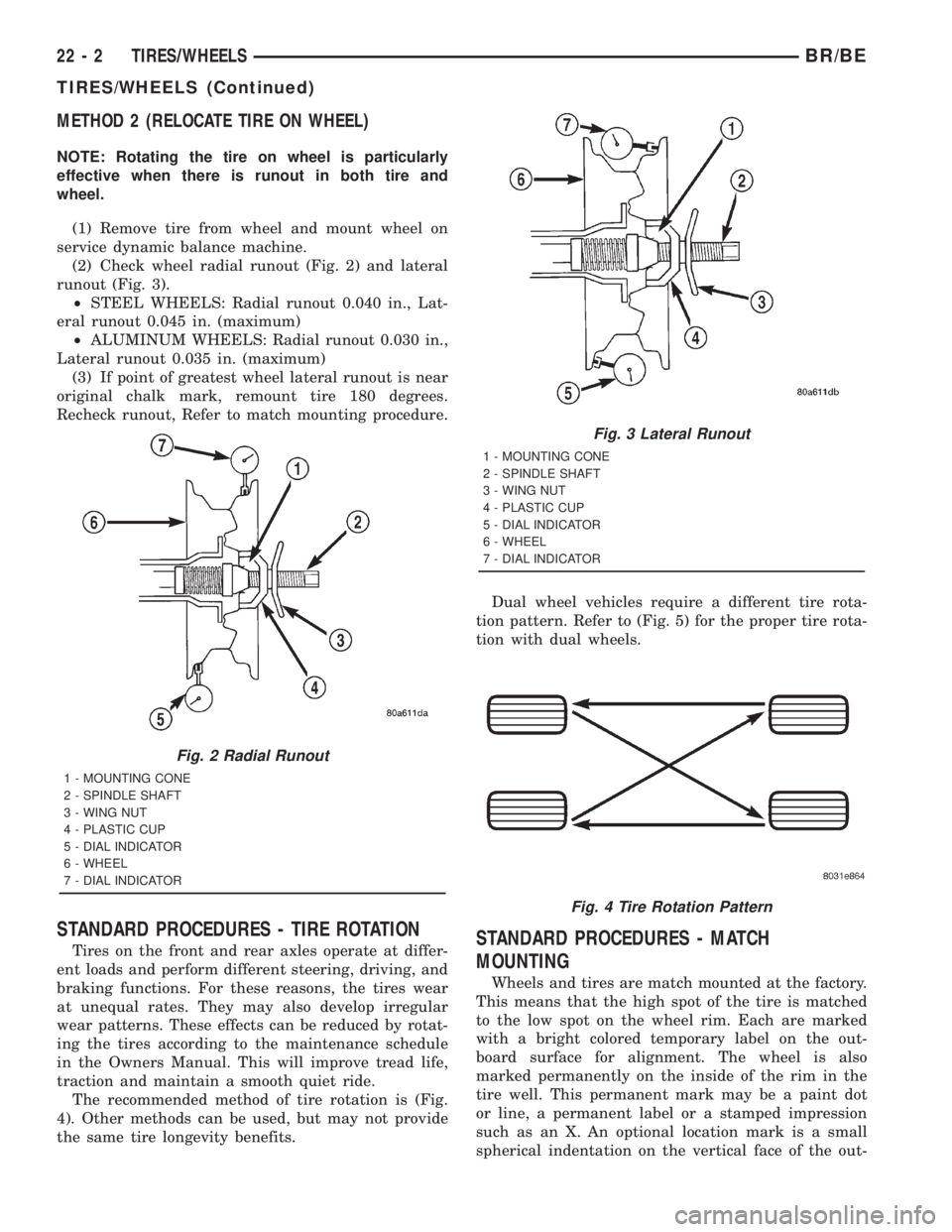
(1) Remove tire from wheel and mount wheel on
service dynamic balance machine.
(2) Check wheel radial runout (Fig. 2) and lateral
runout (Fig. 3).
²STEEL WHEELS: Radial runout 0.040 in., Lat-
eral runout 0.045 in. (maximum)
²ALUMINUM WHEELS: Radial runout 0.030 in.,
Lateral runout 0.035 in. (maximum)
(3) If point of greatest wheel lateral runout is near
original chalk mark, remount tire 180 degrees.
Recheck runout, Refer to match mounting procedure.
STANDARD PROCEDURES - TIRE ROTATION
Tires on the front and rear axles operate at differ-
ent loads and perform different steering, driving, and
braking functions. For these reasons, the tires wear
at unequal rates. They may also develop irregular
wear patterns. These effects can be reduced by rotat-
ing the tires according to the maintenance schedule
in the Owners Manual. This will improve tread life,
traction and maintain a smooth quiet ride.
The recommended method of tire rotation is (Fig.
4). Other methods can be used, but may not provide
the same tire longevity benefits.Dual wheel vehicles require a different tire rota-
tion pattern. Refer to (Fig. 5) for the proper tire rota-
tion with dual wheels.STANDARD PROCEDURES - MATCH
MOUNTING
Wheels and tires are match mounted at the factory.
This means that the high spot of the tire is matched
to the low spot on the wheel rim. Each are marked
with a bright colored temporary label on the out-
board surface for alignment. The wheel is also
marked permanently on the inside of the rim in the
tire well. This permanent mark may be a paint dot
or line, a permanent label or a stamped impression
such as an X. An optional location mark is a small
spherical indentation on the vertical face of the out-
Fig. 2 Radial Runout
1 - MOUNTING CONE
2 - SPINDLE SHAFT
3 - WING NUT
4 - PLASTIC CUP
5 - DIAL INDICATOR
6 - WHEEL
7 - DIAL INDICATOR
Fig. 3 Lateral Runout
1 - MOUNTING CONE
2 - SPINDLE SHAFT
3 - WING NUT
4 - PLASTIC CUP
5 - DIAL INDICATOR
6 - WHEEL
7 - DIAL INDICATOR
Fig. 4 Tire Rotation Pattern
22 - 2 TIRES/WHEELSBR/BE
TIRES/WHEELS (Continued)
Page 2564 of 2889
board flange on some non styled base steel wheels.
The tire must be removed to locate the permanent
mark on the inside of the wheel.
Before dismounting a tire from its wheel, a refer-
ence mark should be placed on the tire at the valve
stem location. This reference will ensure that it is
remounted in the original position on the wheel.
(1) Remove the tire and wheel assembly from the
vehicle and mount on a service dynamic balance
machine.
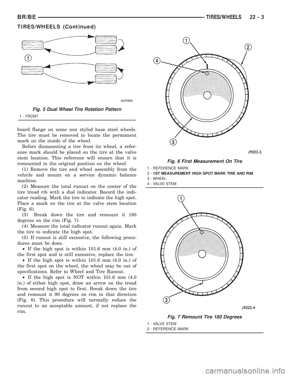
(2) Measure the total runout on the center of the
tire tread rib with a dial indicator. Record the indi-
cator reading. Mark the tire to indicate the high spot.
Place a mark on the tire at the valve stem location
(Fig. 6).
(3) Break down the tire and remount it 180
degrees on the rim (Fig. 7).
(4) Measure the total indicator runout again. Mark
the tire to indicate the high spot.
(5) If runout is still excessive, the following proce-
dures must be done.
²If the high spot is within 101.6 mm (4.0 in.) of
the first spot and is still excessive, replace the tire.
²If the high spot is within 101.6 mm (4.0 in.) of
the first spot on the wheel, the wheel may be out of
specifications. Refer to Wheel and Tire Runout.
²If the high spot is NOT within 101.6 mm (4.0
in.) of either high spot, draw an arrow on the tread
from second high spot to first. Break down the tire
and remount it 90 degrees on rim in that direction
(Fig. 8). This procedure will normally reduce the
runout to an acceptable amount, if not replace the
rim.
Fig. 5 Dual Wheel Tire Rotation Pattern
1 - FRONT
Fig. 6 First Measurement On Tire
1 - REFERENCE MARK
2-1ST MEASUREMENT HIGH SPOT MARK TIRE AND RIM
3 - WHEEL
4 - VALVE STEM
Fig. 7 Remount Tire 180 Degrees
1 - VALVE STEM
2 - REFERENCE MARK
BR/BETIRES/WHEELS 22 - 3
TIRES/WHEELS (Continued)