2001 DODGE RAM service
[x] Cancel search: servicePage 2196 of 2889
ELINE/PROPELLER SHAFT/PROPELLER SHAFT -
REMOVAL)
(6) Remove transmission oil pan, remove gasket,
drain oil and reinstall pan.
(7) If overdrive unit had malfunctioned, or if fluid
is contaminated, remove entire transmission. If diag-
nosis indicated overdrive problems only, remove just
the overdrive unit.
(8) Support transmission with transmission jack.
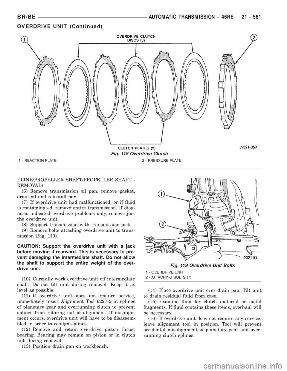
(9) Remove bolts attaching overdrive unit to trans-
mission (Fig. 119).
CAUTION: Support the overdrive unit with a jack
before moving it rearward. This is necessary to pre-
vent damaging the intermediate shaft. Do not allow
the shaft to support the entire weight of the over-
drive unit.
(10) Carefully work overdrive unit off intermediate
shaft. Do not tilt unit during removal. Keep it as
level as possible.
(11) If overdrive unit does not require service,
immediately insert Alignment Tool 6227-2 in splines
of planetary gear and overrunning clutch to prevent
splines from rotating out of alignment. If misalign-
ment occurs, overdrive unit will have to be disassem-
bled in order to realign splines.
(12) Remove and retain overdrive piston thrust
bearing. Bearing may remain on piston or in clutch
hub during removal.
(13) Position drain pan on workbench.(14) Place overdrive unit over drain pan. Tilt unit
to drain residual fluid from case.
(15) Examine fluid for clutch material or metal
fragments. If fluid contains these items, overhaul will
be necessary.
(16) If overdrive unit does not require any service,
leave alignment tool in position. Tool will prevent
accidental misalignment of planetary gear and over-
running clutch splines.
Fig. 118 Overdrive Clutch
1 - REACTION PLATE 2 - PRESSURE PLATE
Fig. 119 Overdrive Unit Bolts
1 - OVERDRIVE UNIT
2 - ATTACHING BOLTS (7)
BR/BEAUTOMATIC TRANSMISSION - 46RE 21 - 561
OVERDRIVE UNIT (Continued)
Page 2204 of 2889
Minor nicks or scratches on components can be
smoothed with crocus cloth. However, do not attempt
to reduce severe scoring on any components with
abrasive materials. Replace severely scored compo-
nents; do not try to salvage them.
INSPECTION
Check condition of the park lock components and
the overdrive case.
Check the bushings in the overdrive case. Replace
the bushings if severely scored or worn. Also replace
the case seal if loose, distorted, or damaged.
Examine the overdrive and direct clutch discs and
plates. Replace the discs if the facing is worn,
severely scored, or burned and flaking off. Replace
the clutch plates if worn, heavily scored, or cracked.
Check the lugs on the clutch plates for wear. The
plates should slide freely in the drum. Replace the
plates or drum if binding occurs.
Check condition of the annulus gear, direct clutch
hub, clutch drum and clutch spring. Replace the gear,
hub and drum if worn or damaged. Replace the
spring if collapsed, distorted, or cracked.
Be sure the splines and lugs on the gear, drum and
hub are in good condition. The clutch plates and
discs should slide freely in these components.
Inspect the thrust bearings and spring plate.
Replace the plate if worn or scored. Replace the bear-
ings if rough, noisy, brinnelled, or worn.
Inspect the planetary gear assembly and the sun
gear and bushings. If either the sun gear or the
bushings are damaged, replace the gear and bush-
ings as an assembly. The gear and bushings are not
serviced separately.
The planetary carrier and pinions must be in good
condition. Also be sure the pinion pins are secure and
in good condition. Replace the carrier if worn or dam-
aged.
Inspect the overrunning clutch and race. The race
surface should be smooth and free of scores. Replace
the overrunning clutch assembly or the race if either
assembly is worn or damaged in any way.
Replace the shaft pilot bushing and inner bushing
if damaged. Replace either shaft bearing if rough or
noisy. Replace the bearing snap-rings if distorted or
cracked.
Check the machined surfaces on the output shaft.
These surfaces should clean and smooth. Very minor
nicks or scratches can be smoothed with crocus cloth.
Replace the shaft if worn, scored or damaged in any
way.
Inspect the output shaft bushings. The small bush-
ing is the intermediate shaft pilot bushing. The large
bushing is the overrunning clutch hub bushing.
Replace either bushing if scored, pitted, cracked, or
worn.
ASSEMBLY
GEARTRAIN AND DIRECT CLUTCH
(1) Soak direct clutch and overdrive clutch discs in
MopartATF +4, type 9602, transmission fluid. Allow
discs to soak for 10-20 minutes.
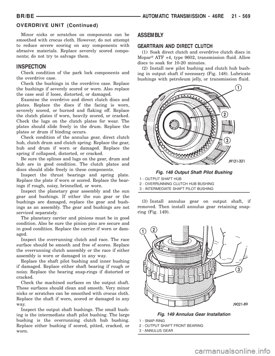
(2) Install new pilot bushing and clutch hub bush-
ing in output shaft if necessary (Fig. 148). Lubricate
bushings with petroleum jelly, or transmission fluid.
(3) Install annulus gear on output shaft, if
removed. Then install annulus gear retaining snap-
ring (Fig. 149).
Fig. 149 Annulus Gear Installation
1 - SNAP-RING
2 - OUTPUT SHAFT FRONT BEARING
3 - ANNULUS GEAR
Fig. 148 Output Shaft Pilot Bushing
1 - OUTPUT SHAFT HUB
2 - OVERRUNNING CLUTCH HUB BUSHING
3 - INTERMEDIATE SHAFT PILOT BUSHING
BR/BEAUTOMATIC TRANSMISSION - 46RE 21 - 569
OVERDRIVE UNIT (Continued)
Page 2213 of 2889
seated and gear splines rotate out of alignment, over-
drive unit will have to be disassembled in order to
realign splines.
(2) If overdrive piston retainer was not removed
during service and original case gasket is no longer
reusable, prepare new gasket by trimming it.
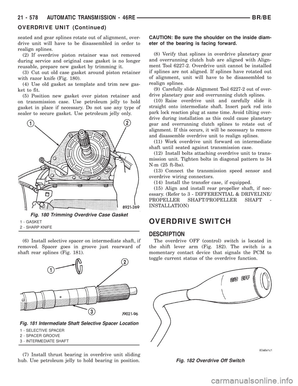
(3) Cut out old case gasket around piston retainer
with razor knife (Fig. 180).
(4) Use old gasket as template and trim new gas-
ket to fit.
(5) Position new gasket over piston retainer and
on transmission case. Use petroleum jelly to hold
gasket in place if necessary. Do not use any type of
sealer to secure gasket. Use petroleum jelly only.
(6) Install selective spacer on intermediate shaft, if
removed. Spacer goes in groove just rearward of
shaft rear splines (Fig. 181).
(7) Install thrust bearing in overdrive unit sliding
hub. Use petroleum jelly to hold bearing in position.CAUTION: Be sure the shoulder on the inside diam-
eter of the bearing is facing forward.
(8) Verify that splines in overdrive planetary gear
and overrunning clutch hub are aligned with Align-
ment Tool 6227-2. Overdrive unit cannot be installed
if splines are not aligned. If splines have rotated out
of alignment, unit will have to be disassembled to
realign splines.
(9)
Carefully slide Alignment Tool 6227-2 out of over-
drive planetary gear and overrunning clutch splines.
(10)Raise overdrive unit and carefully slide it
straight onto intermediate shaft. Insert park rod into
park lock reaction plug at same time. Avoid tilting over-
drive during installation as this could cause planetary
gear and overrunning clutch splines to rotate out of
alignment. If this occurs, it will be necessary to remove
and disassemble overdrive unit to realign splines.
(11) Work overdrive unit forward on intermediate
shaft until seated against transmission case.
(12) Install bolts attaching overdrive unit to trans-
mission unit. Tighten bolts in diagonal pattern to 34
N´m (25 ft-lbs).
(13) Connect the transmission speed sensor and
overdrive wiring connectors.
(14) Install the transfer case, if equipped.
(15) Align and install rear propeller shaft, if nec-
essary. (Refer to 3 - DIFFERENTIAL & DRIVELINE/
PROPELLER SHAFT/PROPELLER SHAFT -
INSTALLATION)
OVERDRIVE SWITCH
DESCRIPTION
The overdrive OFF (control) switch is located in
the shift lever arm (Fig. 182). The switch is a
momentary contact device that signals the PCM to
toggle current status of the overdrive function.
Fig. 180 Trimming Overdrive Case Gasket
1 - GASKET
2 - SHARP KNIFE
Fig. 181 Intermediate Shaft Selective Spacer Location
1 - SELECTIVE SPACER
2 - SPACER GROOVE
3 - INTERMEDIATE SHAFT
Fig. 182 Overdrive Off Switch
21 - 578 AUTOMATIC TRANSMISSION - 46REBR/BE
OVERDRIVE UNIT (Continued)
Page 2222 of 2889
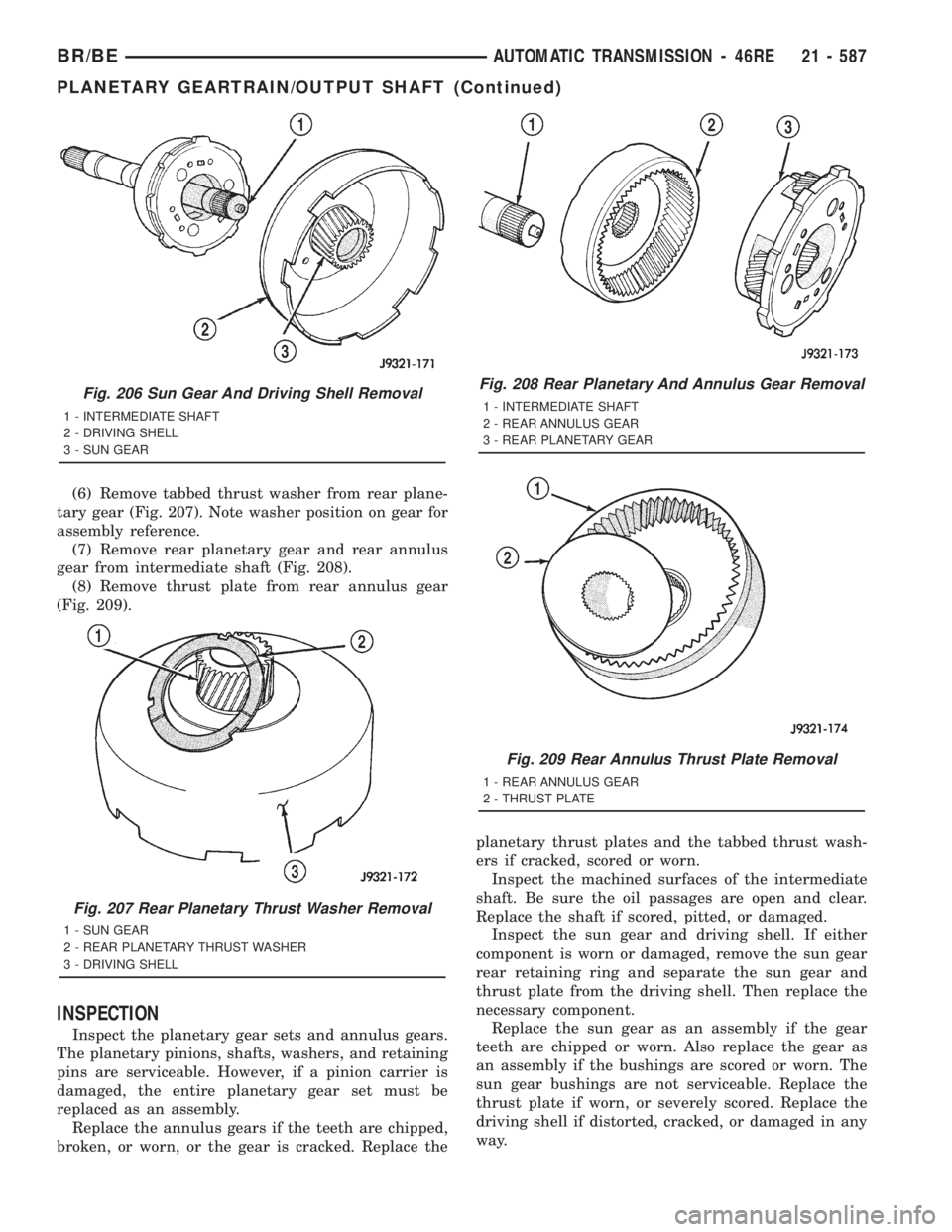
(6) Remove tabbed thrust washer from rear plane-
tary gear (Fig. 207). Note washer position on gear for
assembly reference.
(7) Remove rear planetary gear and rear annulus
gear from intermediate shaft (Fig. 208).
(8) Remove thrust plate from rear annulus gear
(Fig. 209).
INSPECTION
Inspect the planetary gear sets and annulus gears.
The planetary pinions, shafts, washers, and retaining
pins are serviceable. However, if a pinion carrier is
damaged, the entire planetary gear set must be
replaced as an assembly.
Replace the annulus gears if the teeth are chipped,
broken, or worn, or the gear is cracked. Replace theplanetary thrust plates and the tabbed thrust wash-
ers if cracked, scored or worn.
Inspect the machined surfaces of the intermediate
shaft. Be sure the oil passages are open and clear.
Replace the shaft if scored, pitted, or damaged.
Inspect the sun gear and driving shell. If either
component is worn or damaged, remove the sun gear
rear retaining ring and separate the sun gear and
thrust plate from the driving shell. Then replace the
necessary component.
Replace the sun gear as an assembly if the gear
teeth are chipped or worn. Also replace the gear as
an assembly if the bushings are scored or worn. The
sun gear bushings are not serviceable. Replace the
thrust plate if worn, or severely scored. Replace the
driving shell if distorted, cracked, or damaged in any
way.
Fig. 206 Sun Gear And Driving Shell Removal
1 - INTERMEDIATE SHAFT
2 - DRIVING SHELL
3 - SUN GEAR
Fig. 207 Rear Planetary Thrust Washer Removal
1 - SUN GEAR
2 - REAR PLANETARY THRUST WASHER
3 - DRIVING SHELL
Fig. 208 Rear Planetary And Annulus Gear Removal
1 - INTERMEDIATE SHAFT
2 - REAR ANNULUS GEAR
3 - REAR PLANETARY GEAR
Fig. 209 Rear Annulus Thrust Plate Removal
1 - REAR ANNULUS GEAR
2 - THRUST PLATE
BR/BEAUTOMATIC TRANSMISSION - 46RE 21 - 587
PLANETARY GEARTRAIN/OUTPUT SHAFT (Continued)
Page 2235 of 2889
TORQUE CONVERTER
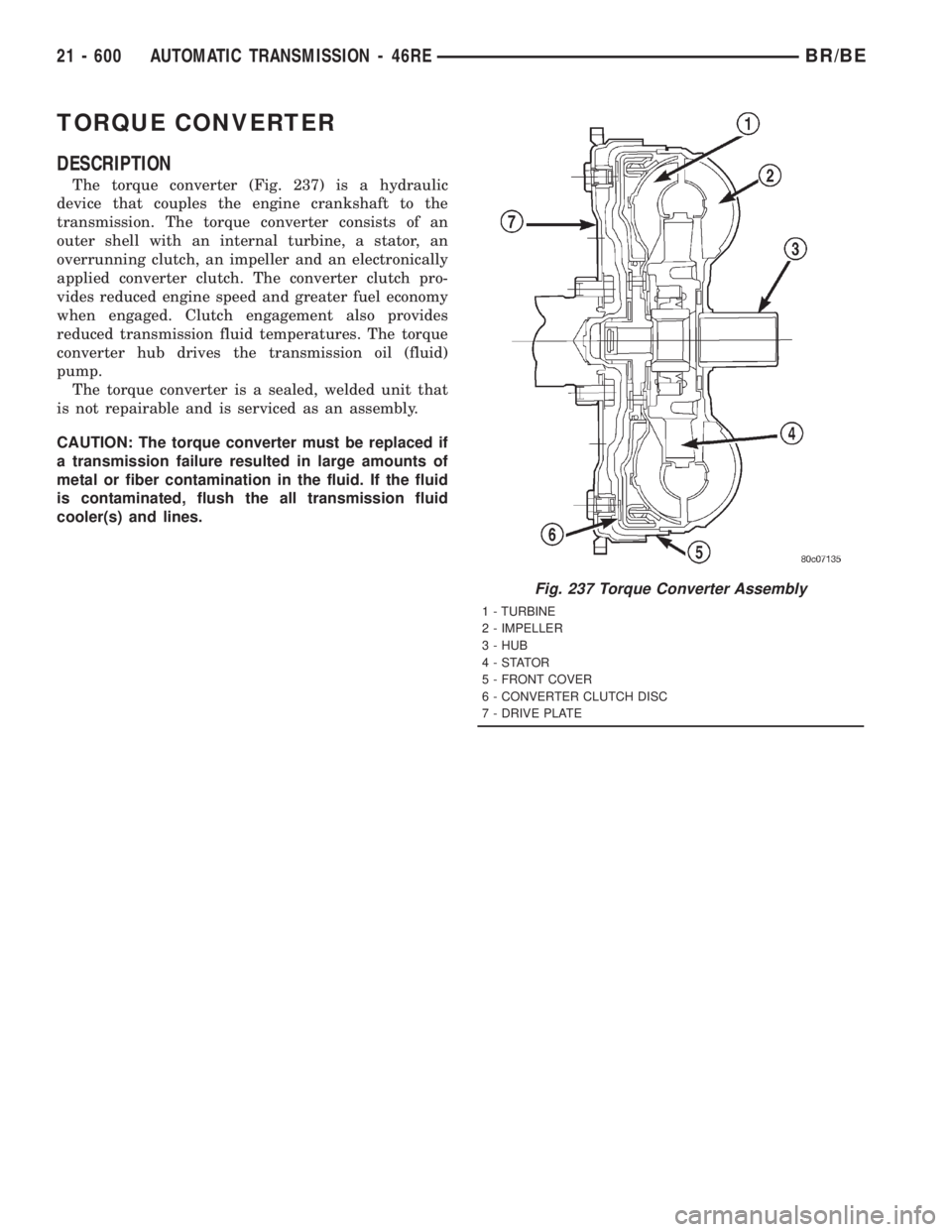
DESCRIPTION
The torque converter (Fig. 237) is a hydraulic
device that couples the engine crankshaft to the
transmission. The torque converter consists of an
outer shell with an internal turbine, a stator, an
overrunning clutch, an impeller and an electronically
applied converter clutch. The converter clutch pro-
vides reduced engine speed and greater fuel economy
when engaged. Clutch engagement also provides
reduced transmission fluid temperatures. The torque
converter hub drives the transmission oil (fluid)
pump.
The torque converter is a sealed, welded unit that
is not repairable and is serviced as an assembly.
CAUTION: The torque converter must be replaced if
a transmission failure resulted in large amounts of
metal or fiber contamination in the fluid. If the fluid
is contaminated, flush the all transmission fluid
cooler(s) and lines.
Fig. 237 Torque Converter Assembly
1 - TURBINE
2 - IMPELLER
3 - HUB
4-STATOR
5 - FRONT COVER
6 - CONVERTER CLUTCH DISC
7 - DRIVE PLATE
21 - 600 AUTOMATIC TRANSMISSION - 46REBR/BE
Page 2241 of 2889
STANDARD PROCEDURE - TORQUE
CONVERTER DRAINBACK VALVE
The converter drainback check valve is located in
the cooler outlet (pressure) line near the radiator
tank. The valve prevents fluid drainback when the
vehicle is parked for lengthy periods. The valve check
ball is spring loaded and has an opening pressure of
approximately 2 psi.
The valve is serviced as an assembly; it is not
repairable. Do not clean the valve if restricted, or
contaminated by sludge, or debris. If the valve fails,
or if a transmission malfunction occurs that gener-
ates significant amounts of sludge and/or clutch par-
ticles and metal shavings, the valve must be
replaced.
The valve must be removed whenever the cooler
and lines are reverse flushed. The valve can be flow
tested when necessary. The procedure is exactly the
same as for flow testing a cooler.
If the valve is restricted, installed backwards, or in
the wrong line, it will cause an overheating condition
and possible transmission failure.
CAUTION: The drainback valve is a one-way flow
device. It must be properly oriented in terms of flow
direction for the cooler to function properly. The
valve must be installed in the pressure line. Other-
wise flow will be blocked and would cause an over-
heating condition and eventual transmission failure.
TRANSMISSION
TEMPERATURE SENSOR
DESCRIPTION
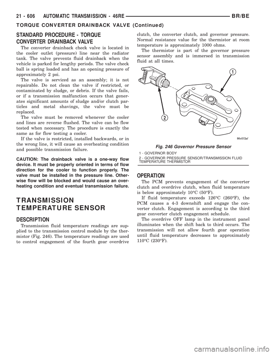
Transmission fluid temperature readings are sup-
plied to the transmission control module by the ther-
mistor (Fig. 246). The temperature readings are used
to control engagement of the fourth gear overdriveclutch, the converter clutch, and governor pressure.
Normal resistance value for the thermistor at room
temperature is approximately 1000 ohms.
The thermistor is part of the governor pressure
sensor assembly and is immersed in transmission
fluid at all times.
OPERATION
The PCM prevents engagement of the converter
clutch and overdrive clutch, when fluid temperature
is below approximately 10ÉC (50ÉF).
If fluid temperature exceeds 126ÉC (260ÉF), the
PCM causes a 4-3 downshift and engage the con-
verter clutch. Engagement is according to the third
gear converter clutch engagement schedule.
The overdrive OFF lamp in the instrument panel
illuminates when the shift back to third occurs. The
transmission will not allow fourth gear operation
until fluid temperature decreases to approximately
110ÉC (230ÉF).
Fig. 246 Governor Pressure Sensor
1 - GOVERNOR BODY
2 - GOVERNOR PRESSURE SENSOR/TRANSMISSION FLUID
TEMPERATURE THERMISTOR
21 - 606 AUTOMATIC TRANSMISSION - 46REBR/BE
TORQUE CONVERTER DRAINBACK VALVE (Continued)
Page 2260 of 2889
BOOST VALVE
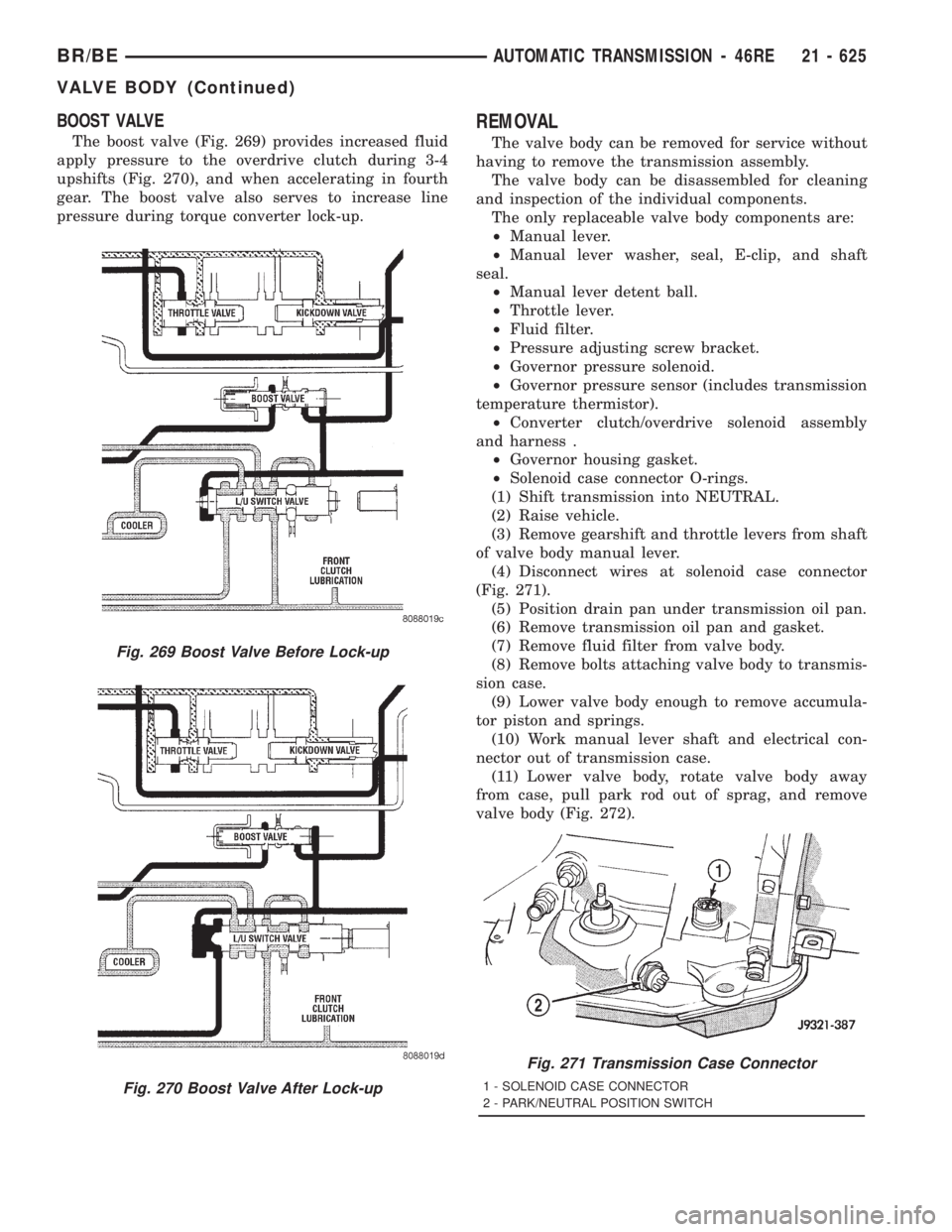
The boost valve (Fig. 269) provides increased fluid
apply pressure to the overdrive clutch during 3-4
upshifts (Fig. 270), and when accelerating in fourth
gear. The boost valve also serves to increase line
pressure during torque converter lock-up.
REMOVAL
The valve body can be removed for service without
having to remove the transmission assembly.
The valve body can be disassembled for cleaning
and inspection of the individual components.
The only replaceable valve body components are:
²Manual lever.
²Manual lever washer, seal, E-clip, and shaft
seal.
²Manual lever detent ball.
²Throttle lever.
²Fluid filter.
²Pressure adjusting screw bracket.
²Governor pressure solenoid.
²Governor pressure sensor (includes transmission
temperature thermistor).
²Converter clutch/overdrive solenoid assembly
and harness .
²Governor housing gasket.
²Solenoid case connector O-rings.
(1) Shift transmission into NEUTRAL.
(2) Raise vehicle.
(3) Remove gearshift and throttle levers from shaft
of valve body manual lever.
(4) Disconnect wires at solenoid case connector
(Fig. 271).
(5) Position drain pan under transmission oil pan.
(6) Remove transmission oil pan and gasket.
(7) Remove fluid filter from valve body.
(8) Remove bolts attaching valve body to transmis-
sion case.
(9) Lower valve body enough to remove accumula-
tor piston and springs.
(10) Work manual lever shaft and electrical con-
nector out of transmission case.
(11) Lower valve body, rotate valve body away
from case, pull park rod out of sprag, and remove
valve body (Fig. 272).
Fig. 269 Boost Valve Before Lock-up
Fig. 270 Boost Valve After Lock-up
Fig. 271 Transmission Case Connector
1 - SOLENOID CASE CONNECTOR
2 - PARK/NEUTRAL POSITION SWITCH
BR/BEAUTOMATIC TRANSMISSION - 46RE 21 - 625
VALVE BODY (Continued)
Page 2272 of 2889
3-4 ACCUMULATOR HOUSING
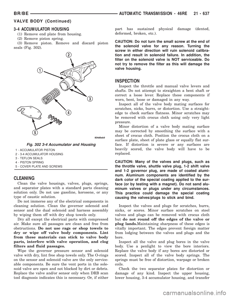
(1) Remove end plate from housing.
(2) Remove piston spring.
(3) Remove piston. Remove and discard piston
seals (Fig. 302).
CLEANING
Clean the valve housings, valves, plugs, springs,
and separator plates with a standard parts cleaning
solution only. Do not use gasoline, kerosene, or any
type of caustic solution.
Do not immerse any of the electrical components in
cleaning solution. Clean the governor solenoid and
sensor and the dual solenoid and harness assembly
by wiping them off with dry shop towels only.
Dry all except the electrical parts with compressed
air. Make sure all passages are clean and free from
obstructions.Do not use rags or shop towels to
dry or wipe off valve body components. Lint
from these materials can stick to valve body
parts, interfere with valve operation, and clog
filters and fluid passages.
Wipe the governor pressure sensor and solenoid
valve with dry, lint free shop towels only. The O-rings
on the sensor and solenoid valve are the only service-
able components. Be sure the vent ports in the sole-
noid valve are open and not blocked by dirt or debris.
Replace the valve and/or sensor only when DRB scan
tool diagnosis indicates this is necessary. Or, if eitherpart has sustained physical damage (dented,
deformed, broken, etc.).
CAUTION: Do not turn the small screw at the end of
the solenoid valve for any reason. Turning the
screw in either direction will ruin solenoid calibra-
tion and result in solenoid failure. In addition, the
filter on the solenoid valve is NOT serviceable. Do
not try to remove the filter as this will damage the
valve housing.
INSPECTION
Inspect the throttle and manual valve levers and
shafts. Do not attempt to straighten a bent shaft or
correct a loose lever. Replace these components if
worn, bent, loose or damaged in any way.
Inspect all of the valve body mating surfaces for
scratches, nicks, burrs, or distortion. Use a straight-
edge to check surface flatness. Minor scratches may
be removed with crocus cloth using only very light
pressure.
Minor distortion of a valve body mating surface
may be corrected by smoothing the surface with a
sheet of crocus cloth. Position the crocus cloth on a
surface plate, sheet of plate glass or equally flat sur-
face. If distortion is severe or any surfaces are
heavily scored, the valve body will have to be
replaced.
CAUTION: Many of the valves and plugs, such as
the throttle valve, shuttle valve plug, 1-2 shift valve
and 1-2 governor plug, are made of coated alumi-
num. Aluminum components are identified by the
dark color of the special coating applied to the sur-
face (or by testing with a magnet). Do not sand alu-
minum valves or plugs under any circumstances.
This practice could damage the special coating
causing the valves/plugs to stick and bind.
Inspect the valves and plugs for scratches, burrs,
nicks, or scores. Minor surface scratches on steel
valves and plugs can be removed with crocus cloth
butdo not round off the edges of the valve or
plug lands.Maintaining sharpness of these edges is
vitally important. The edges prevent foreign matter
from lodging between the valves and plugs and the
bore.
Inspect all the valve and plug bores in the valve
body. Use a penlight to view the bore interiors.
Replace the valve body if any bores are distorted or
scored. Inspect all of the valve body springs. The
springs must be free of distortion, warpage or broken
coils.
Check the two separator plates for distortion or
damage of any kind. Inspect the upper housing,
lower housing, 3-4 accumulator housing, and transfer
Fig. 302 3-4 Accumulator and Housing
1 - ACCUMULATOR PISTON
2 - 3-4 ACCUMULATOR HOUSING
3 - TEFLON SEALS
4 - PISTON SPRING
5 - COVER PLATE AND SCREWS
BR/BEAUTOMATIC TRANSMISSION - 46RE 21 - 637
VALVE BODY (Continued)