2001 DODGE RAM tire type
[x] Cancel search: tire typePage 518 of 2889
MIRROR SWITCH
DESCRIPTION
The heated mirror switch, the heated mirror sys-
tem indicator lamp, the heated mirror system solid
state electronic control logic and timer circuitry and
the heated mirror relay are all integral to the a/c
heater control, which is located between the instru-
ment cluster and the radio near the center of the
instrument cluster bezel on the instrument panel.
The heated mirror switch and the heated mirror sys-
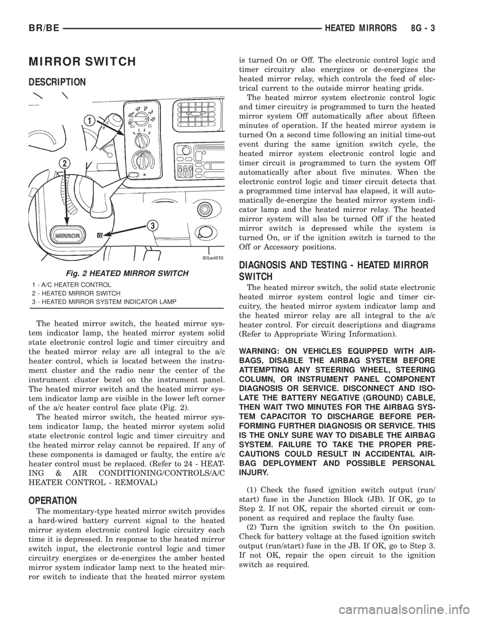
tem indicator lamp are visible in the lower left corner
of the a/c heater control face plate (Fig. 2).
The heated mirror switch, the heated mirror sys-
tem indicator lamp, the heated mirror system solid
state electronic control logic and timer circuitry and
the heated mirror relay cannot be repaired. If any of
these components is damaged or faulty, the entire a/c
heater control must be replaced. (Refer to 24 - HEAT-
ING & AIR CONDITIONING/CONTROLS/A/C
HEATER CONTROL - REMOVAL)
OPERATION
The momentary-type heated mirror switch provides
a hard-wired battery current signal to the heated
mirror system electronic control logic circuitry each
time it is depressed. In response to the heated mirror
switch input, the electronic control logic and timer
circuitry energizes or de-energizes the amber heated
mirror system indicator lamp next to the heated mir-
ror switch to indicate that the heated mirror systemis turned On or Off. The electronic control logic and
timer circuitry also energizes or de-energizes the
heated mirror relay, which controls the feed of elec-
trical current to the outside mirror heating grids.
The heated mirror system electronic control logic
and timer circuitry is programmed to turn the heated
mirror system Off automatically after about fifteen
minutes of operation. If the heated mirror system is
turned On a second time following an initial time-out
event during the same ignition switch cycle, the
heated mirror system electronic control logic and
timer circuit is programmed to turn the system Off
automatically after about five minutes. When the
electronic control logic and timer circuit detects that
a programmed time interval has elapsed, it will auto-
matically de-energize the heated mirror system indi-
cator lamp and the heated mirror relay. The heated
mirror system will also be turned Off if the heated
mirror switch is depressed while the system is
turned On, or if the ignition switch is turned to the
Off or Accessory positions.
DIAGNOSIS AND TESTING - HEATED MIRROR
SWITCH
The heated mirror switch, the solid state electronic
heated mirror system control logic and timer cir-
cuitry, the heated mirror system indicator lamp and
the heated mirror relay are all integral to the a/c
heater control. For circuit descriptions and diagrams
(Refer to Appropriate Wiring Information).
WARNING: ON VEHICLES EQUIPPED WITH AIR-
BAGS, DISABLE THE AIRBAG SYSTEM BEFORE
ATTEMPTING ANY STEERING WHEEL, STEERING
COLUMN, OR INSTRUMENT PANEL COMPONENT
DIAGNOSIS OR SERVICE. DISCONNECT AND ISO-
LATE THE BATTERY NEGATIVE (GROUND) CABLE,
THEN WAIT TWO MINUTES FOR THE AIRBAG SYS-
TEM CAPACITOR TO DISCHARGE BEFORE PER-
FORMING FURTHER DIAGNOSIS OR SERVICE. THIS
IS THE ONLY SURE WAY TO DISABLE THE AIRBAG
SYSTEM. FAILURE TO TAKE THE PROPER PRE-
CAUTIONS COULD RESULT IN ACCIDENTAL AIR-
BAG DEPLOYMENT AND POSSIBLE PERSONAL
INJURY.
(1) Check the fused ignition switch output (run/
start) fuse in the Junction Block (JB). If OK, go to
Step 2. If not OK, repair the shorted circuit or com-
ponent as required and replace the faulty fuse.
(2) Turn the ignition switch to the On position.
Check for battery voltage at the fused ignition switch
output (run/start) fuse in the JB. If OK, go to Step 3.
If not OK, repair the open circuit to the ignition
switch as required.
Fig. 2 HEATED MIRROR SWITCH
1 - A/C HEATER CONTROL
2 - HEATED MIRROR SWITCH
3 - HEATED MIRROR SYSTEM INDICATOR LAMP
BR/BEHEATED MIRRORS 8G - 3
Page 553 of 2889
SPARK PLUG
DESCRIPTION
The 3.9L V-6 and 5.2L/5.9L V-8 engines use resis-
tor type spark plugs. The 8.0L V-10 engine uses
inductive type spark plugs.
Spark plug resistance values range from 6,000 to
20,000 ohms (when checked with at least a 1000 volt
spark plug tester).Do not use an ohmmeter to
check the resistance values of the spark plugs.
Inaccurate readings will result.
OPERATION
To prevent possible pre-ignition and/or mechanical
engine damage, the correct type/heat range/number
spark plug must be used.
Always use the recommended torque when tighten-
ing spark plugs. Incorrect torque can distort the
spark plug and change plug gap. It can also pull the
plug threads and do possible damage to both the
spark plug and the cylinder head.
Remove the spark plugs and examine them for
burned electrodes and fouled, cracked or broken por-
celain insulators. Keep plugs arranged in the order
in which they were removed from the engine. A sin-gle plug displaying an abnormal condition indicates
that a problem exists in the corresponding cylinder.
Replace spark plugs at the intervals recommended in
Group O, Lubrication and Maintenance
Spark plugs that have low mileage may be cleaned
and reused if not otherwise defective, carbon or oil
fouled. Also refer to Spark Plug Conditions.
CAUTION: Never use a motorized wire wheel brush
to clean the spark plugs. Metallic deposits will
remain on the spark plug insulator and will cause
plug misfire.
DIAGNOSIS AND TESTING - SPARK PLUG
CONDITIONS
NORMAL OPERATING
The few deposits present on the spark plug will
probably be light tan or slightly gray in color. This is
evident with most grades of commercial gasoline
(Fig. 29). There will not be evidence of electrode
burning. Gap growth will not average more than
approximately 0.025 mm (.001 in) per 3200 km (2000
miles) of operation. Spark plugs that have normal
wear can usually be cleaned, have the electrodes
filed, have the gap set and then be installed.
Some fuel refiners in several areas of the United
States have introduced a manganese additive (MMT)
for unleaded fuel. During combustion, fuel with MMT
causes the entire tip of the spark plug to be coated
with a rust colored deposit. This rust color can be
misdiagnosed as being caused by coolant in the com-
bustion chamber. Spark plug performance may be
affected by MMT deposits.
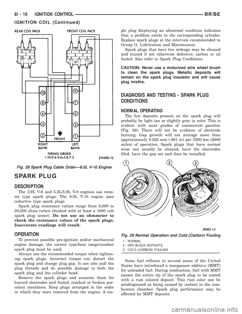
Fig. 28 Spark Plug Cable OrderÐ8.0L V-10 Engine
Fig. 29 Normal Operation and Cold (Carbon) Fouling
1 - NORMAL
2 - DRY BLACK DEPOSITS
3 - COLD (CARBON) FOULING
8I - 16 IGNITION CONTROLBR/BE
IGNITION COIL (Continued)
Page 557 of 2889
With the engine running, remove spark plug cable
from spark plug (one at a time) and hold next to a
good engine ground. If the cable and spark plug are
in good condition, the engine rpm should drop and
the engine will run poorly. If engine rpm does not
drop, the cable and/or spark plug may not be operat-
ing properly and should be replaced. Also check
engine cylinder compression.
With the engine not running, connect one end of a
test probe to a good ground. Start the engine and run
the other end of the test probe along the entire
length of all spark plug cables. If cables are cracked
or punctured, there will be a noticeable spark jump
from the damaged area to the test probe. The cable
running from the ignition coil to the distributor cap
can be checked in the same manner. Cracked, dam-
aged or faulty cables should be replaced with resis-
tance type cable. This can be identified by the words
ELECTRONIC SUPPRESSION printed on the cable
jacket.
Use an ohmmeter to test for open circuits, exces-
sive resistance or loose terminals. If equipped,
remove the distributor cap from the distributor.Do
not remove cables from cap.Remove cable from
spark plug. Connect ohmmeter to spark plug termi-
nal end of cable and to corresponding electrode in
distributor cap. Resistance should be 250 to 1000
Ohms per inch of cable. If not, remove cable from dis-
tributor cap tower and connect ohmmeter to the ter-
minal ends of cable. If resistance is not within
specifications as found in the SPARK PLUG CABLE
RESISTANCE chart, replace the cable. Test all spark
plug cables in this manner.
SPARK PLUG CABLE RESISTANCE
MINIMUM MAXIMUM
250 Ohms Per Inch 1000 Ohms Per Inch
3000 Ohms Per Foot 12,000 Ohms Per Foot
To test ignition coil-to-distributor cap cable, do not
remove the cable from the cap. Connect ohmmeter to
rotor button (center contact) of distributor cap and
terminal at ignition coil end of cable. If resistance is
not within specifications as found in the Spark Plug
Cable Resistance chart, remove the cable from the
distributor cap. Connect the ohmmeter to the termi-
nal ends of the cable. If resistance is not within spec-
ifications as found in the Spark Plug Cable
Resistance chart, replace the cable. Inspect the igni-
tion coil tower for cracks, burns or corrosion.
REMOVAL
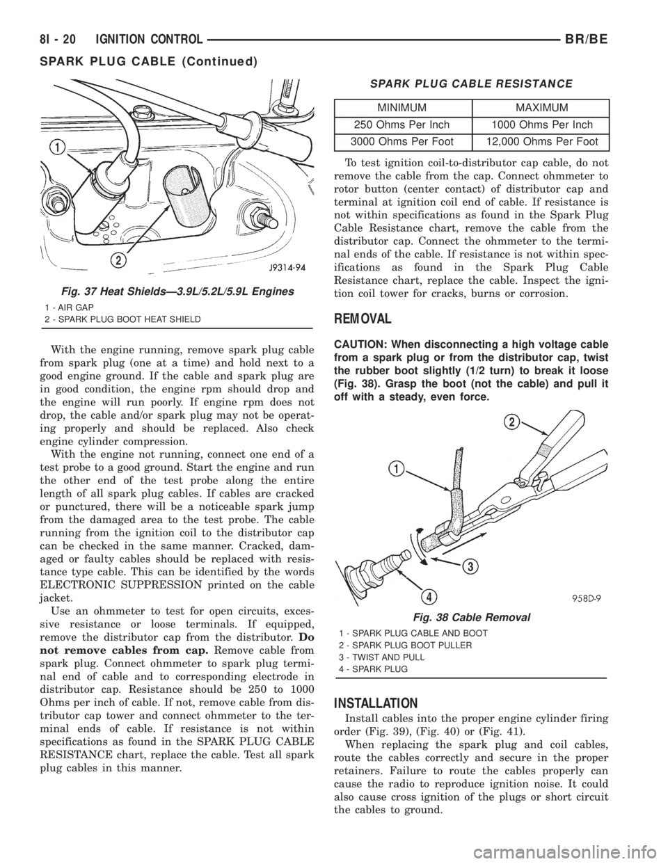
CAUTION: When disconnecting a high voltage cable
from a spark plug or from the distributor cap, twist
the rubber boot slightly (1/2 turn) to break it loose
(Fig. 38). Grasp the boot (not the cable) and pull it
off with a steady, even force.
INSTALLATION
Install cables into the proper engine cylinder firing
order (Fig. 39), (Fig. 40) or (Fig. 41).
When replacing the spark plug and coil cables,
route the cables correctly and secure in the proper
retainers. Failure to route the cables properly can
cause the radio to reproduce ignition noise. It could
also cause cross ignition of the plugs or short circuit
the cables to ground.
Fig. 37 Heat ShieldsÐ3.9L/5.2L/5.9L Engines
1 - AIR GAP
2 - SPARK PLUG BOOT HEAT SHIELD
Fig. 38 Cable Removal
1 - SPARK PLUG CABLE AND BOOT
2 - SPARK PLUG BOOT PULLER
3 - TWIST AND PULL
4 - SPARK PLUG
8I - 20 IGNITION CONTROLBR/BE
SPARK PLUG CABLE (Continued)
Page 562 of 2889
²Check Gauges Indicator
²Cruise Indicator (Odometer VFD)
²Four-Wheel Drive Indicator
²High Beam Indicator
²Low Fuel Indicator
²Washer Fluid Indicator
²Malfunction Indicator Lamp (MIL)
²Overdrive-Off Indicator
²Seatbelt Indicator
²Service Reminder Indicator (SRI)
²Transmission Overtemp Indicator
²Turn Signal (Right and Left) Indicators
²Upshift Indicator
²Wait-To-Start Indicator (Diesel Only)
²Water-In-Fuel Indicator (Diesel Only)
Some of these indicators are either programmable
or automatically configured when the EMIC is con-
nected to the vehicle electrical system. This feature
allows those indicators to be activated or deactivated
for compatibility with certain optional equipment.
The EMIC also includes a provision for mounting the
automatic transmission gear selector indicator in the
lower right corner of the cluster. The spring-loaded,
cable driven, mechanical gear selector indicator gives
an indication of the transmission gear that has been
selected with the automatic transmission gear selec-
tor lever. The gear selector indicator pointer is easily
visible through an opening provided in the front of
the cluster overlay, and is also lighted by the cluster
illumination lamps for visibility at night. Models
equipped with a manual transmission have a block-
out plate installed in place of the gear selector indi-
cator.
Cluster illumination is accomplished by adjustable
incandescent back lighting, which illuminates the
gauges for visibility when the exterior lighting is
turned on. The EMIC high beam indicator, turn sig-
nal indicators, and wait-to-start indicator are also
illuminated by dedicated incandescent bulbs. The
remaining indicators in the EMIC are each illumi-
nated by a dedicated Light Emitting Diode (LED)
that is soldered onto the electronic circuit board.
Each of the incandescent bulbs is secured by an inte-
gral bulb holder to the electronic circuit board from
the back of the cluster housing.
Hard wired circuitry connects the EMIC to the
electrical system of the vehicle. These hard wired cir-
cuits are integral to several wire harnesses, which
are routed throughout the vehicle and retained by
many different methods. These circuits may be con-
nected to each other, to the vehicle electrical system
and to the EMIC through the use of a combination of
soldered splices, splice block connectors, and many
different types of wire harness terminal connectors
and insulators. Refer to the appropriate wiring infor-
mation. The wiring information includes wiring dia-grams, proper wire and connector repair procedures,
further details on wire harness routing and reten-
tion, as well as pin-out and location views for the
various wire harness connectors, splices and grounds.
The EMIC modules for this model are serviced only
as complete units. The EMIC module cannot be
adjusted or repaired. If a gauge, an LED indicator,
the VFD, the electronic circuit board, the circuit
board hardware, the cluster overlay, or the EMIC
housing are damaged or faulty, the entire EMIC mod-
ule must be replaced. The cluster lens and hood unit,
the rear cluster housing cover, the automatic trans-
mission gear selector indicator, and the incandescent
lamp bulbs with holders are available for individual
service replacement.
OPERATION
The ElectroMechanical Instrument Cluster (EMIC)
is designed to allow the vehicle operator to monitor
the conditions of many of the vehicle components and
operating systems. The gauges and indicators in the
EMIC provide valuable information about the various
standard and optional powertrains, fuel and emis-
sions systems, cooling systems, lighting systems,
safety systems and many other convenience items.
The EMIC is installed in the instrument panel so
that all of these monitors can be easily viewed by the
vehicle operator when driving, while still allowing
relative ease of access for service. The microproces-
sor-based EMIC hardware and software uses various
inputs to control the gauges and indicators visible on
the face of the cluster. Some of these inputs are hard
wired, but most are in the form of electronic mes-
sages that are transmitted by other electronic mod-
ules over the Chrysler Collision Detection (CCD) data
bus network. (Refer to 8 - ELECTRICAL/ELEC-
TRONIC CONTROL MODULES/COMMUNICATION
- OPERATION).
The EMIC microprocessor smooths the input data
using algorithms to provide gauge readings that are
accurate, stable and responsive to operating condi-
tions. These algorithms are designed to provide
gauge readings during normal operation that are con-
sistent with customer expectations. However, when
abnormal conditions exist, such as low/high battery
voltage, low oil pressure, or high coolant tempera-
ture, the algorithm drives the gauge pointer to an
extreme position and the microprocessor turns on the
Check Gauges indicator to provide a distinct visual
indication of a problem to the vehicle operator. The
instrument cluster circuitry may also generate a
hard wired chime tone request to the Central Timer
Module (CTM) when it monitors certain conditions or
inputs, in order to provide the vehicle operator with
an audible alert.
BR/BEINSTRUMENT CLUSTER 8J - 3
INSTRUMENT CLUSTER (Continued)
Page 605 of 2889
will become high and the IC signals the PNP transis-
tor to de-energize the circuit. This cycling will con-
tinue until the right or left turn signal switch is
turned off.
A special design feature of the combination flasher
allows it to9sense9that a turn signal circuit or bulb
is not operating, and provide the driver an indication
of the condition by flashing the remaining bulbs in
the affected circuit at a higher rate (120 flashes-per-
minute or higher). Conventional flashers either con-
tinue flashing at their typical rate (heavy-duty type),
or discontinue flashing the affected circuit entirely
(standard-duty type). During turn signal operation,
the combination flasher IC compares normal battery
voltage input on pin 2 with the shunt resistor voltage
input on pin 7. If the IC9senses9that the voltage dif-
ference between pin 2 and pin 7 is different than the
pre-calibrated value of the IC, it will increase the
rate at which it signals the PNP transistor to ener-
gize the pin 1 output. Thus, the inoperative half (left
or right side) of the turn signal circuit will flash
faster.
Because of the active electronic elements within
the combination flasher, it cannot be tested with con-
ventional automotive electrical test equipment. If the
combination flasher is believed to be faulty, test the
turn signal system and hazard warning system. Then
replace the combination flasher with a known good
unit to confirm system operation. (Refer to 8 - ELEC-
TRICAL/LAMPS/LIGHTING - EXTERIOR/TURN
SIGNAL & HAZARD WARNING SYSTEM - DIAG-
NOSIS AND TESTING).
REMOVAL
WARNING: ON VEHICLES EQUIPPED WITH AIR-
BAGS, DISABLE THE AIRBAG SYSTEM BEFORE
ATTEMPTING ANY STEERING WHEEL, STEERING
COLUMN, OR INSTRUMENT PANEL COMPONENT
DIAGNOSIS OR SERVICE. DISCONNECT AND ISO-
LATE THE BATTERY NEGATIVE (GROUND) CABLE,
THEN WAIT TWO MINUTES FOR THE AIRBAG SYS-
TEM CAPACITOR TO DISCHARGE BEFORE PER-
FORMING FURTHER DIAGNOSIS OR SERVICE. THIS
IS THE ONLY SURE WAY TO DISABLE THE AIRBAG
SYSTEM. FAILURE TO TAKE THE PROPER PRE-
CAUTIONS COULD RESULT IN ACCIDENTAL AIR-
BAG DEPLOYMENT AND POSSIBLE PERSONAL
INJURY.
(1) Disconnect and isolate the battery negative
cable.
(2) Remove the fuse access panel by unsnapping it
from the left outboard end of the instrument panel.
(3) Remove the combination flasher from the Junc-
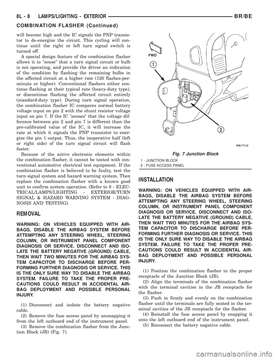
tion Block (JB) (Fig. 7).
INSTALLATION
WARNING: ON VEHICLES EQUIPPED WITH AIR-
BAGS, DISABLE THE AIRBAG SYSTEM BEFORE
ATTEMPTING ANY STEERING WHEEL, STEERING
COLUMN, OR INSTRUMENT PANEL COMPONENT
DIAGNOSIS OR SERVICE. DISCONNECT AND ISO-
LATE THE BATTERY NEGATIVE (GROUND) CABLE,
THEN WAIT TWO MINUTES FOR THE AIRBAG SYS-
TEM CAPACITOR TO DISCHARGE BEFORE PER-
FORMING FURTHER DIAGNOSIS OR SERVICE. THIS
IS THE ONLY SURE WAY TO DISABLE THE AIRBAG
SYSTEM. FAILURE TO TAKE THE PROPER PRE-
CAUTIONS COULD RESULT IN ACCIDENTAL AIR-
BAG DEPLOYMENT AND POSSIBLE PERSONAL
INJURY.
(1) Position the combination flasher in the proper
receptacle of the Junction Block (JB).
(2) Align the terminals of the combination flasher
with the terminal cavities in the JB receptacle for
the flasher.
(3) Push in firmly and evenly on the combination
flasher until the terminals are fully seated in the ter-
minal cavities of the JB receptacle for the flasher.
(4) Reinstall the fuse access panel by snapping it
onto the left outboard end of the instrument panel.
(5) Reconnect the battery negative cable.
Fig. 7 Junction Block
1 - JUNCTION BLOCK
2 - FUSE ACCESS PANEL
8L - 8 LAMPS/LIGHTING - EXTERIORBR/BE
COMBINATION FLASHER (Continued)
Page 651 of 2889
On those models equipped with the optional RKE
system, the power lock system also includes the fol-
lowing components, which are described in further
detail elsewhere in this service manual:
²Central Timer Module- The high-line or pre-
mium Central Timer Module (CTM) is located under
the driver side end of the instrument panel, inboard
of the instrument panel steering column opening.
The high-line or premium CTM contains a micropro-
cessor and software that allow it to provide the many
electronic functions and features not available with
base version of the power lock system.
²Door Cylinder Lock Switches- A resistor-
multiplexed switch located on the back of each front
door lock cylinder allows the power door lock system
to be operated using a key inserted in either the
driver or passenger front door lock cylinder.
Some of the additional features of the power lock
system found in vehicles with the RKE system option
include:
²Automatic Door Lock- The high-line/premium
CTM provides an optional automatic door lock fea-
ture (also known as rolling door locks). This is a pro-
grammable feature.
²Central Locking- The high-line/premium CTM
provides an optional central locking/unlocking fea-
ture.
²Door Lock Inhibit- The high-line/premium
CTM provides a door lock inhibit feature.
²Enhanced Accident Response- The high-line/
premium CTM provides an optional enhanced acci-
dent response feature. This is a programmable
feature.
Hard wired circuitry connects the power lock sys-
tem components to the electrical system of the vehi-
cle. These hard wired circuits are integral to several
wire harnesses, which are routed throughout the
vehicle and retained by many different methods.
These circuits may be connected to each other, to the
vehicle electrical system and to the power lock sys-
tem components through the use of a combination of
soldered splices, splice block connectors, and many
different types of wire harness terminal connectors
and insulators. Refer to the appropriate wiring infor-
mation. The wiring information includes wiring dia-
grams, proper wire and connector repair procedures,
further details on wire harness routing and reten-
tion, as well as pin-out and location views for the
various wire harness connectors, splices and grounds.
Many of the electronic features in the vehicle con-
trolled or supported by the high-line or premium ver-
sions of the CTM are programmable using the
DRBIIItscan tool. In addition, the high-line/pre-
mium CTM software is Flash compatible, which
means it can be reprogrammed using Flash repro-
gramming procedures. However, if any of the CTMhardware components are damaged or faulty, the
entire CTM unit must be replaced. The power lock
system components and the hard wired inputs or out-
puts of the CTM can be diagnosed using conventional
diagnostic tools and methods; however, for diagnosis
of the high-line or premium versions of the CTM or
the CCD data bus, the use of a DRBIIItscan tool is
required. Refer to the appropriate diagnostic infor-
mation.
DESCRIPTION - REMOTE KEYLESS ENTRY
SYSTEM
A Remote Keyless Entry (RKE) system is an avail-
able option on this model. The Remote Keyless Entry
(RKE) system is a Radio Frequency (RF) system that
allows the remote operation of the power lock system
and, if the vehicle is so equipped, the Vehicle Theft
Security System (VTSS). (Refer to 8 - ELECTRICAL/
VEHICLE THEFT SECURITY - DESCRIPTION).
The RKE system includes the following major compo-
nents, which are described in further detail else-
where in this service manual:
²Central Timer Module- The high-line or pre-
mium Central Timer Module (CTM) is located under
the driver side end of the instrument panel, inboard
of the instrument panel steering column opening.
The high-line or premium CTM contains a micropro-
cessor, an RF receiver, and the software that allow it
to provide the many electronic functions and features
of the RKE system.
²Keyless Entry Transmitter- The keyless
entry transmitter is a small, battery-powered, RF
transmitter that is contained within a molded plastic
case that is designed to also serve as a convenient
key fob.
Some additional features of the RKE system
include:
²Horn Chirp- This feature provides a short,
sharp chirp of the vehicle horn to give an audible
confirmation that a valid Lock signal has been
received from the RKE transmitter. This feature can
be enabled or disabled and, if enabled, one of two
optional horn chirp durations (twenty or forty milli-
seconds) can also be selected.
²Illuminated Entry- This feature turns on the
courtesy lamps in the vehicle for a timed interval
(about thirty seconds) each time a valid Unlock sig-
nal has been received from the RKE transmitter.
²Panic Mode- This feature allows the vehicle
operator to cause the vehicle horn to pulse, the head-
lights to flash, and the courtesy lamps to illuminate
for about three minutes by depressing a Panic button
on the RKE transmitter. Pressing the Panic button a
second time will cancel the Panic mode. A vehicle
speed of about 24 kilometers-per-hour (15 miles-per-
hour) will also cancel the panic mode.
8N - 2 POWER LOCKSBR/BE
POWER LOCKS (Continued)
Page 670 of 2889
the motor and drive unit of the power seat recliner
mechanism is secured with two screws to the seat
cushion frame, and is concealed by the outboard seat
cushion side shield.
The power seat recliner cannot be repaired. If the
unit is faulty or damaged, it must be replaced. Refer
toBucket Seat Reclinerin Body for the service
procedure.
OPERATION
The power seat recliner includes a reversible elec-
tric motor that is secured to the lower hinge plate of
the recliner unit. The motor is connected to a gearbox
that moves the upper hinge plate of the power seat
recliner through a screw-type drive unit.
DIAGNOSIS & TESTING - POWER SEAT
RECLINER
Following are tests that will help to diagnose the
hard wired components and circuits of the power seat
system. Actuate the power seat recliner switch to
move the power seat recliner adjuster in each direc-
tion. The power seat recliner adjuster should move in
both directions. If the power seat recliner adjuster
fails to operate in only one direction, move the
adjuster a short distance in the opposite direction
and test again to be certain that the adjuster is not
at its travel limit. If the power seat recliner adjuster
still fails to operate in only one direction, refer to
Power Seat Switchin the Diagnosis and Testing
section of this group. If the power recliner adjuster
fails to operate in either direction, perform the fol-
lowing tests. For complete circuit diagrams, refer to
Power Seatin Wiring Diagrams.
(1) Check the power seat circuit breaker in the
junction block. If OK, go to Step 2. If not OK, replace
the faulty power seat circuit breaker.
(2) Check for battery voltage at the power seat cir-
cuit breaker in the junction block. If OK, go to Step
3. If not OK, repair the open fused B(+) circuit to the
fuse in the Power Distribution Center as required.
(3) Remove the outboard seat cushion side shield
from the seat. Disconnect the seat wire harness con-
nector from the power seat switch connector recepta-
cle. Check for battery voltage at the fused B(+)
circuit cavity of the power seat wire harness connec-
tor for the power seat switch. If OK, go to Step 4. If
not OK, repair the open fused B(+) circuit to the
power seat circuit breaker in the junction block as
required.
(4) Check for continuity between the ground cir-
cuit cavity of the power seat wire harness connector
for the power seat switch and a good ground. There
should be continuity. If OK, go to Step 5. If not OK,
repair the open ground circuit to ground as required.(5) Test the power seat switch. Refer toPower
Seat Switchin the Diagnosis and Testing section of
this group. If the switch tests OK, test the circuits of
the power seat wire harness between the power seat
recliner adjuster motor and the power seat switch for
shorts or opens. If the circuits check OK, replace the
faulty power seat recliner unit. If the circuits are not
OK, repair the power seat wire harness as required.
POWER SEAT TRACK
DESCRIPTION
There are three reversible motors that operate the
power seat adjuster. The motors are connected to
worm-drive gearboxes that move the seat adjuster
through a combination of screw-type drive units.
The front and rear of a seat are operated by differ-
ent motors. They can be raised or lowered indepen-
dently of each other. When the center seat switch is
pushed in the Up or Down direction, both the front
and rear motors operate in unison. On standard cab
models the entire seat is moved up or down, on
extended cab models (club cab and quad cab) the seat
cushion moves independently of the seat back in the
up or down directions. The forward-rearward motor
is operated by pushing the center seat switch in the
Forward or Rearward direction, which moves the
entire seat in the selected direction on all models.
Each motor contains a self-resetting circuit breaker
to protect it from overload. Consecutive or frequent
resetting of the circuit breakers must not be allowed
to continue, or the motors may be damaged. Make
the necessary repairs.
The power seat adjuster and motors cannot be
repaired, and are serviced only as a complete unit. If
any component in this unit is faulty or damaged, the
entire power seat adjuster and motors assembly must
be replaced.
OPERATION
When a power seat switch is actuated, a battery
feed and a ground path are applied through the
switch contacts to the motor(s). The motor(s) and
drive unit(s) operate to move the seat in the selected
direction until the switch is released, or until the
travel limit of the power seat adjuster is reached.
When the switch is moved in the opposite direction,
the battery feed and ground path to the motor(s) are
reversed through the switch contacts. This causes the
motor to run in the opposite direction.
DIAGNOSIS & TESTING - POWER SEAT TRACK
For circuit descriptions and diagrams, refer to Wir-
ing Diagrams.
BR/BEPOWER SEAT SYSTEM 8N - 21
RECLINER MOTOR (Continued)
Page 678 of 2889

Deployment of the airbags depends upon the angle
and severity of the impact. The airbag system is
designed to deploy upon a frontal impact within a
thirty degree angle from either side of the vehicle
center line. Deployment is not based upon vehicle
speed; rather, deployment is based upon the rate of
deceleration as measured by the forces of gravity (G
force) upon the airbag system impact sensor, which is
integral to the ACM. When a frontal impact is severe
enough, the microprocessor in the ACM signals the
inflator units of both airbag modules to deploy the
airbags. During a frontal vehicle impact, the knee
blockers work in concert with properly fastened and
adjusted seat belts to restrain both the driver and
the front seat passenger in the proper position for an
airbag deployment. The knee blockers also absorb
and distribute the crash energy from the driver and
the front seat passenger to the structure of the
instrument panel.
Typically, the driver and front seat passenger recall
more about the events preceding and following a col-
lision than they have of the airbag deployment itself.
This is because the airbag deployment and deflation
occur so rapidly. In a typical 48 kilometer-per-hour
(30 mile-per-hour) barrier impact, from the moment
of impact until both airbags are fully inflated takes
about 40 milliseconds. Within one to two seconds
from the moment of impact, both airbags are almost
entirely deflated. The times cited for these events are
approximations, which apply only to a barrier impact
at the given speed. Actual times will vary somewhat,
depending upon the vehicle speed, impact angle,
severity of the impact, and the type of collision.
When the ACM monitors a problem in any of the
airbag system circuits or components, it stores a
fault code or Diagnostic Trouble Code (DTC) in its
memory circuit and sends an electronic message to
the EMIC to turn on the airbag indicator. Proper
testing of the airbag system components, the
Chrysler Collision Detection (CCD) data bus, the
data bus message inputs to and outputs from the
EMIC or the ACM, as well as the retrieval or erasure
of a DTC from the ACM requires the use of a
DRBIIItscan tool. Refer to the appropriate diagnos-
tic information.
See the owner's manual in the vehicle glove box for
more information on the features, use and operation
of all of the factory-installed passenger restraints,
including the airbag system.
WARNING
WARNING: THE AIRBAG SYSTEM IS A SENSITIVE,
COMPLEX ELECTROMECHANICAL UNIT. BEFORE
ATTEMPTING TO DIAGNOSE OR SERVICE ANY AIR-
BAG SYSTEM OR RELATED STEERING WHEEL,STEERING COLUMN, OR INSTRUMENT PANEL
COMPONENTS YOU MUST FIRST DISCONNECT
AND ISOLATE THE BATTERY NEGATIVE (GROUND)
CABLE. THEN WAIT TWO MINUTES FOR THE SYS-
TEM CAPACITOR TO DISCHARGE BEFORE FUR-
THER SYSTEM SERVICE. THIS IS THE ONLY SURE
WAY TO DISABLE THE AIRBAG SYSTEM. FAILURE
TO DO THIS COULD RESULT IN ACCIDENTAL AIR-
BAG DEPLOYMENT AND POSSIBLE PERSONAL
INJURY.
WARNING: THE DRIVER AIRBAG INFLATOR UNIT
CONTAINS SODIUM AZIDE AND POTASSIUM
NITRATE. THESE MATERIALS ARE POISONOUS
AND EXTREMELY FLAMMABLE. CONTACT WITH
ACID, WATER, OR HEAVY METALS MAY PRODUCE
HARMFUL AND IRRITATING GASES (SODIUM
HYDROXIDE IS FORMED IN THE PRESENCE OF
MOISTURE) OR COMBUSTIBLE COMPOUNDS. THE
PASSENGER AIRBAG UNIT CONTAINS ARGON GAS
PRESSURIZED TO OVER 2500 PSI. DO NOT
ATTEMPT TO DISMANTLE AN AIRBAG UNIT OR
TAMPER WITH ITS INFLATOR. DO NOT PUNCTURE,
INCINERATE, OR BRING INTO CONTACT WITH
ELECTRICITY. DO NOT STORE AT TEMPERATURES
EXCEEDING 93É C (200É F).
WARNING: REPLACE AIRBAG SYSTEM COMPO-
NENTS ONLY WITH PARTS SPECIFIED IN THE
DAIMLERCHRYSLER MOPAR PARTS CATALOG.
SUBSTITUTE PARTS MAY APPEAR INTERCHANGE-
ABLE, BUT INTERNAL DIFFERENCES MAY RESULT
IN INFERIOR OCCUPANT PROTECTION.
WARNING: THE FASTENERS, SCREWS, AND
BOLTS ORIGINALLY USED FOR THE AIRBAG SYS-
TEM COMPONENTS HAVE SPECIAL COATINGS
AND ARE SPECIFICALLY DESIGNED FOR THE AIR-
BAG SYSTEM. THEY MUST NEVER BE REPLACED
WITH ANY SUBSTITUTES. ANY TIME A NEW FAS-
TENER IS NEEDED, REPLACE IT WITH THE COR-
RECT FASTENERS PROVIDED IN THE SERVICE
PACKAGE OR SPECIFIED IN THE DAIMLER-
CHRYSLER MOPAR PARTS CATALOG.
WARNING: WHEN A STEERING COLUMN HAS AN
AIRBAG UNIT ATTACHED, NEVER PLACE THE COL-
UMN ON THE FLOOR OR ANY OTHER SURFACE
WITH THE STEERING WHEEL OR AIRBAG UNIT
FACE DOWN.
BR/BERESTRAINTS 8O - 3
RESTRAINTS (Continued)