2001 DODGE RAM charging
[x] Cancel search: chargingPage 600 of 2889
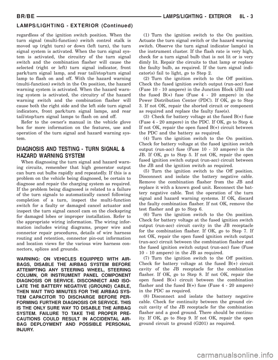
regardless of the ignition switch position. When the
turn signal (multi-function) switch control stalk is
moved up (right turn) or down (left turn), the turn
signal system is activated. When the turn signal sys-
tem is activated, the circuitry of the turn signal
switch and the combination flasher will cause the
selected (right or left) turn signal indicator, front
park/turn signal lamp, and rear tail/stop/turn signal
lamp to flash on and off. With the hazard warning
(multi-function) switch in the On position, the hazard
warning system is activated. When the hazard warn-
ing system is activated, the circuitry of the hazard
warning switch and the combination flasher will
cause both the right side and the left side turn signal
indicators, front park/turn signal lamps, and rear
tail/stop/turn signal lamps to flash on and off.
Refer to the owner's manual in the vehicle glove
box for more information on the features, use and
operation of the turn signal and hazard warning sys-
tem.
DIAGNOSIS AND TESTING - TURN SIGNAL &
HAZARD WARNING SYSTEM
When diagnosing the turn signal and hazard warn-
ing circuits, remember that high generator output
can burn out bulbs rapidly and repeatedly. If this is a
problem on the vehicle being diagnosed, be certain to
diagnose and repair the charging system as required.
If the problem being diagnosed is related to a failure
of the turn signals to automatically cancel following
completion of a turn, inspect the multi-function
switch for a faulty or damaged cancel actuator and
inspect the turn signal cancel cam on the clockspring
for damaged lobes or improper installation. Refer to
the appropriate wiring information. The wiring infor-
mation includes wiring diagrams, proper wire and
connector repair procedures, details of wire harness
routing and retention, connector pin-out information
and location views for the various wire harness con-
nectors, splices and grounds.
WARNING: ON VEHICLES EQUIPPED WITH AIR-
BAGS, DISABLE THE AIRBAG SYSTEM BEFORE
ATTEMPTING ANY STEERING WHEEL, STEERING
COLUMN, OR INSTRUMENT PANEL COMPONENT
DIAGNOSIS OR SERVICE. DISCONNECT AND ISO-
LATE THE BATTERY NEGATIVE (GROUND) CABLE,
THEN WAIT TWO MINUTES FOR THE AIRBAG SYS-
TEM CAPACITOR TO DISCHARGE BEFORE PER-
FORMING FURTHER DIAGNOSIS OR SERVICE. THIS
IS THE ONLY SURE WAY TO DISABLE THE AIRBAG
SYSTEM. FAILURE TO TAKE THE PROPER PRE-
CAUTIONS COULD RESULT IN ACCIDENTAL AIR-
BAG DEPLOYMENT AND POSSIBLE PERSONAL
INJURY.(1) Turn the ignition switch to the On position.
Actuate the turn signal switch or the hazard warning
switch. Observe the turn signal indicator lamp(s) in
the instrument cluster. If the flash rate is very high,
check for a turn signal bulb that is not lit or is very
dimly lit. Repair the circuits to that lamp or replace
the faulty bulb, as required. If the turn signal indi-
cator(s) fail to light, go to Step 2.
(2) Turn the ignition switch to the Off position.
Check the fused ignition switch output (run-acc) fuse
(Fuse 10 - 10 ampere) in the Junction Block (JB) and
the fused B(+) fuse (Fuse4-20ampere) in the
Power Distribution Center (PDC). If OK, go to Step
3. If not OK, repair the shorted circuit or component
as required and replace the faulty fuse(s).
(3) Check for battery voltage at the fused B(+) fuse
(Fuse4-20ampere) in the PDC. If OK, go to Step 4.
If not OK, repair the open fused B(+) circuit between
the PDC and the battery as required.
(4) Turn the ignition switch to the On position.
Check for battery voltage at the fused ignition switch
output (run-acc) fuse (Fuse 10 - 10 ampere) in the
JB. If OK, go to Step 5. If not OK, repair the open
fused ignition switch output (run-acc) circuit between
the JB and the ignition switch as required.
(5) Turn the ignition switch to the Off position.
Disconnect and isolate the battery negative cable.
Remove the combination flasher from the JB and
replace it with a known good unit. Reconnect the bat-
tery negative cable. Test the operation of the turn
signal and hazard warning systems. If OK, discard
the faulty combination flasher. If not OK, remove the
test flasher and go to Step 6.
(6) Turn the ignition switch to the On position.
Check for battery voltage at the fused ignition switch
output (run-acc) circuit cavity in the JB receptacle
for the combination flasher. If OK, go to Step 7. If
not OK, repair the open fused ignition switch output
(run-acc) circuit between the combination flasher and
the fused ignition switch output (run-acc) fuse (Fuse
10 - 10 ampere) in the JB as required.
(7) Turn the ignition switch to the Off position.
Check for battery voltage at the fused B(+) circuit
cavity of the JB receptacle for the combination
flasher. If OK, go to Step 8. If not OK, repair the
open fused B(+) circuit between the combination
flasher and the fused B(+) fuse (Fuse4-20ampere)
in the PDC as required.
(8) Disconnect and isolate the battery negative
cable. Check for continuity between the ground cir-
cuit cavity of the JB receptacle for the combination
flasher and a good ground. There should be continu-
ity. If OK, go to Step 9. If not OK, repair the open
ground circuit to ground (G201) as required.
BR/BELAMPS/LIGHTING - EXTERIOR 8L - 3
LAMPS/LIGHTING - EXTERIOR (Continued)
Page 606 of 2889
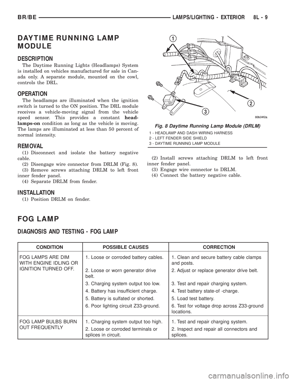
DAYTIME RUNNING LAMP
MODULE
DESCRIPTION
The Daytime Running Lights (Headlamps) System
is installed on vehicles manufactured for sale in Can-
ada only. A separate module, mounted on the cowl,
controls the DRL.
OPERATION
The headlamps are illuminated when the ignition
switch is turned to the ON position. The DRL module
receives a vehicle-moving signal from the vehicle
speed sensor. This provides a constanthead-
lamps-oncondition as long as the vehicle is moving.
The lamps are illuminated at less than 50 percent of
normal intensity.
REMOVAL
(1) Disconnect and isolate the battery negative
cable.
(2) Disengage wire connector from DRLM (Fig. 8).
(3) Remove screws attaching DRLM to left front
inner fender panel.
(4) Separate DRLM from fender.
INSTALLATION
(1) Position DRLM on fender.(2) Install screws attaching DRLM to left front
inner fender panel.
(3) Engage wire connector to DRLM.
(4) Connect the battery negative cable.
FOG LAMP
DIAGNOSIS AND TESTING - FOG LAMP
CONDITION POSSIBLE CAUSES CORRECTION
FOG LAMPS ARE DIM
WITH ENGINE IDLING OR
IGNITION TURNED OFF.1. Loose or corroded battery cables. 1. Clean and secure battery cable clamps
and posts.
2. Loose or worn generator drive
belt.2. Adjust or replace generator drive belt.
3. Charging system output too low. 3. Test and repair charging system.
4. Battery has insufficient charge. 4. Test battery state-of -charge.
5. Battery is sulfated or shorted. 5. Load test battery.
6. Poor lighting circuit Z33-ground. 6. Test for voltage drop across Z33-ground
locations.
FOG LAMP BULBS BURN
OUT FREQUENTLY1. Charging system output too high. 1. Test and repair charging system.
2. Loose or corroded terminals or
splices in circuit.2. Inspect and repair all connectors and
splices.
Fig. 8 Daytime Running Lamp Module (DRLM)
1 - HEADLAMP AND DASH WIRING HARNESS
2 - LEFT FENDER SIDE SHIELD
3 - DAYTIME RUNNING LAMP MODULE
BR/BELAMPS/LIGHTING - EXTERIOR 8L - 9
Page 607 of 2889
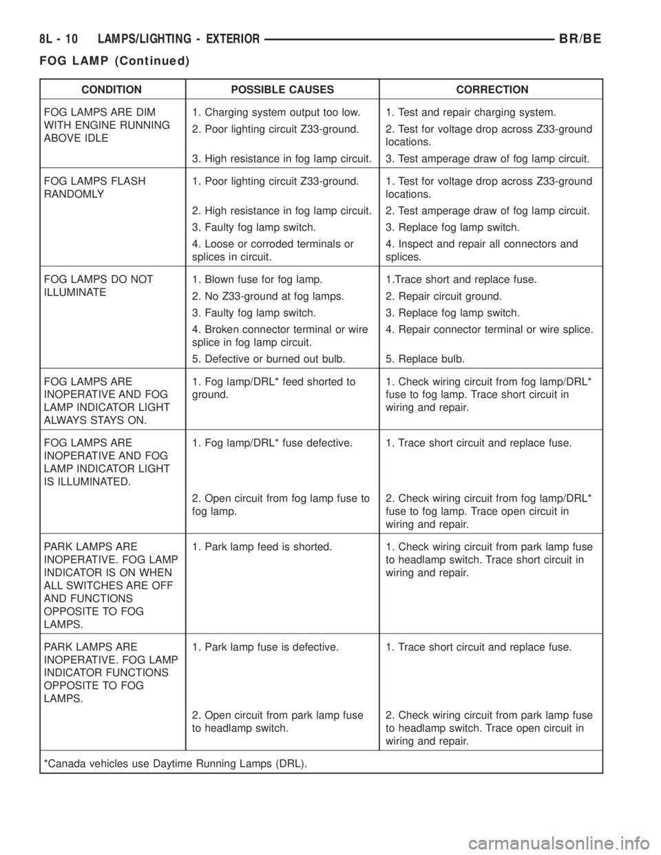
CONDITION POSSIBLE CAUSES CORRECTION
FOG LAMPS ARE DIM
WITH ENGINE RUNNING
ABOVE IDLE1. Charging system output too low. 1. Test and repair charging system.
2. Poor lighting circuit Z33-ground. 2. Test for voltage drop across Z33-ground
locations.
3. High resistance in fog lamp circuit. 3. Test amperage draw of fog lamp circuit.
FOG LAMPS FLASH
RANDOMLY1. Poor lighting circuit Z33-ground. 1. Test for voltage drop across Z33-ground
locations.
2. High resistance in fog lamp circuit. 2. Test amperage draw of fog lamp circuit.
3. Faulty fog lamp switch. 3. Replace fog lamp switch.
4. Loose or corroded terminals or
splices in circuit.4. Inspect and repair all connectors and
splices.
FOG LAMPS DO NOT
ILLUMINATE1. Blown fuse for fog lamp. 1.Trace short and replace fuse.
2. No Z33-ground at fog lamps. 2. Repair circuit ground.
3. Faulty fog lamp switch. 3. Replace fog lamp switch.
4. Broken connector terminal or wire
splice in fog lamp circuit.4. Repair connector terminal or wire splice.
5. Defective or burned out bulb. 5. Replace bulb.
FOG LAMPS ARE
INOPERATIVE AND FOG
LAMP INDICATOR LIGHT
ALWAYS STAYS ON.1. Fog lamp/DRL* feed shorted to
ground.1. Check wiring circuit from fog lamp/DRL*
fuse to fog lamp. Trace short circuit in
wiring and repair.
FOG LAMPS ARE
INOPERATIVE AND FOG
LAMP INDICATOR LIGHT
IS ILLUMINATED.1. Fog lamp/DRL* fuse defective. 1. Trace short circuit and replace fuse.
2. Open circuit from fog lamp fuse to
fog lamp.2. Check wiring circuit from fog lamp/DRL*
fuse to fog lamp. Trace open circuit in
wiring and repair.
PARK LAMPS ARE
INOPERATIVE. FOG LAMP
INDICATOR IS ON WHEN
ALL SWITCHES ARE OFF
AND FUNCTIONS
OPPOSITE TO FOG
LAMPS.1. Park lamp feed is shorted. 1. Check wiring circuit from park lamp fuse
to headlamp switch. Trace short circuit in
wiring and repair.
PARK LAMPS ARE
INOPERATIVE. FOG LAMP
INDICATOR FUNCTIONS
OPPOSITE TO FOG
LAMPS.1. Park lamp fuse is defective. 1. Trace short circuit and replace fuse.
2. Open circuit from park lamp fuse
to headlamp switch.2. Check wiring circuit from park lamp fuse
to headlamp switch. Trace open circuit in
wiring and repair.
*Canada vehicles use Daytime Running Lamps (DRL).
8L - 10 LAMPS/LIGHTING - EXTERIORBR/BE
FOG LAMP (Continued)
Page 611 of 2889
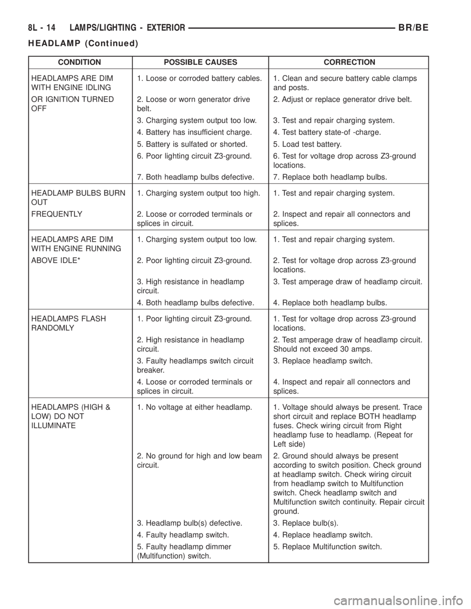
CONDITION POSSIBLE CAUSES CORRECTION
HEADLAMPS ARE DIM
WITH ENGINE IDLING1. Loose or corroded battery cables. 1. Clean and secure battery cable clamps
and posts.
OR IGNITION TURNED
OFF2. Loose or worn generator drive
belt.2. Adjust or replace generator drive belt.
3. Charging system output too low. 3. Test and repair charging system.
4. Battery has insufficient charge. 4. Test battery state-of -charge.
5. Battery is sulfated or shorted. 5. Load test battery.
6. Poor lighting circuit Z3-ground. 6. Test for voltage drop across Z3-ground
locations.
7. Both headlamp bulbs defective. 7. Replace both headlamp bulbs.
HEADLAMP BULBS BURN
OUT1. Charging system output too high. 1. Test and repair charging system.
FREQUENTLY 2. Loose or corroded terminals or
splices in circuit.2. Inspect and repair all connectors and
splices.
HEADLAMPS ARE DIM
WITH ENGINE RUNNING1. Charging system output too low. 1. Test and repair charging system.
ABOVE IDLE* 2. Poor lighting circuit Z3-ground. 2. Test for voltage drop across Z3-ground
locations.
3. High resistance in headlamp
circuit.3. Test amperage draw of headlamp circuit.
4. Both headlamp bulbs defective. 4. Replace both headlamp bulbs.
HEADLAMPS FLASH
RANDOMLY1. Poor lighting circuit Z3-ground. 1. Test for voltage drop across Z3-ground
locations.
2. High resistance in headlamp
circuit.2. Test amperage draw of headlamp circuit.
Should not exceed 30 amps.
3. Faulty headlamps switch circuit
breaker.3. Replace headlamp switch.
4. Loose or corroded terminals or
splices in circuit.4. Inspect and repair all connectors and
splices.
HEADLAMPS (HIGH &
LOW) DO NOT
ILLUMINATE1. No voltage at either headlamp. 1. Voltage should always be present. Trace
short circuit and replace BOTH headlamp
fuses. Check wiring circuit from Right
headlamp fuse to headlamp. (Repeat for
Left side)
2. No ground for high and low beam
circuit.2. Ground should always be present
according to switch position. Check ground
at headlamp switch. Check wiring circuit
from headlamp switch to Multifunction
switch. Check headlamp switch and
Multifunction switch continuity. Repair circuit
ground.
3. Headlamp bulb(s) defective. 3. Replace bulb(s).
4. Faulty headlamp switch. 4. Replace headlamp switch.
5. Faulty headlamp dimmer
(Multifunction) switch.5. Replace Multifunction switch.
8L - 14 LAMPS/LIGHTING - EXTERIORBR/BE
HEADLAMP (Continued)
Page 742 of 2889
WIRING
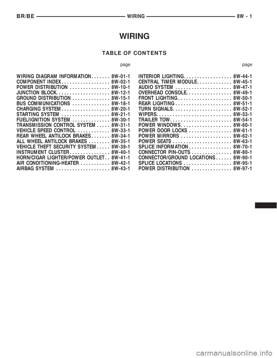
TABLE OF CONTENTS
page page
WIRING DIAGRAM INFORMATION....... 8W-01-1
COMPONENT INDEX.................. 8W-02-1
POWER DISTRIBUTION............... 8W-10-1
JUNCTION BLOCK.................... 8W-12-1
GROUND DISTRIBUTION.............. 8W-15-1
BUS COMMUNICATIONS.............. 8W-18-1
CHARGING SYSTEM.................. 8W-20-1
STARTING SYSTEM.................. 8W-21-1
FUEL/IGNITION SYSTEM.............. 8W-30-1
TRANSMISSION CONTROL SYSTEM..... 8W-31-1
VEHICLE SPEED CONTROL............ 8W-33-1
REAR WHEEL ANTILOCK BRAKES....... 8W-34-1
ALL WHEEL ANTILOCK BRAKES........ 8W-35-1
VEHICLE THEFT SECURITY SYSTEM..... 8W-39-1
INSTRUMENT CLUSTER............... 8W-40-1
HORN/CIGAR LIGHTER/POWER OUTLET . . 8W-41-1
AIR CONDITIONING-HEATER........... 8W-42-1
AIRBAG SYSTEM.................... 8W-43-1INTERIOR LIGHTING.................. 8W-44-1
CENTRAL TIMER MODULE............. 8W-45-1
AUDIO SYSTEM..................... 8W-47-1
OVERHEAD CONSOLE................. 8W-49-1
FRONT LIGHTING.................... 8W-50-1
REAR LIGHTING..................... 8W-51-1
TURN SIGNALS...................... 8W-52-1
WIPERS............................ 8W-53-1
TRAILER TOW....................... 8W-54-1
POWER WINDOWS................... 8W-60-1
POWER DOOR LOCKS................ 8W-61-1
POWER MIRRORS................... 8W-62-1
POWER SEATS...................... 8W-63-1
SPLICE INFORMATION................ 8W-70-1
CONNECTOR PIN-OUTS............... 8W-80-1
CONNECTOR/GROUND LOCATIONS...... 8W-90-1
SPLICE LOCATIONS.................. 8W-95-1
POWER DISTRIBUTION............... 8W-97-1 BR/BEWIRING 8W - 1
Page 830 of 2889
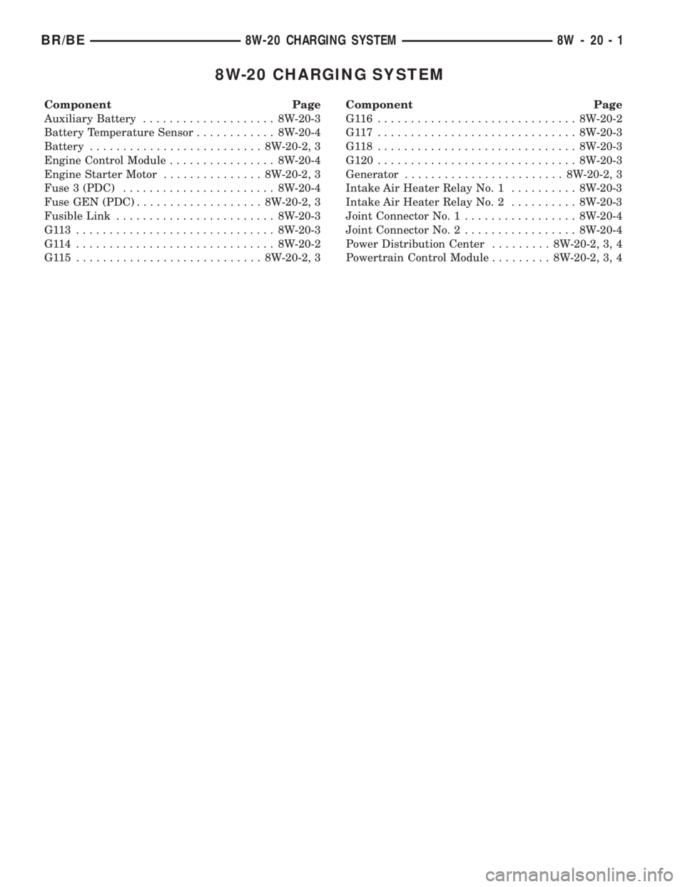
8W-20 CHARGING SYSTEM
Component Page
Auxiliary Battery.................... 8W-20-3
Battery Temperature Sensor............ 8W-20-4
Battery.......................... 8W-20-2, 3
Engine Control Module................ 8W-20-4
Engine Starter Motor............... 8W-20-2, 3
Fuse 3 (PDC)....................... 8W-20-4
Fuse GEN (PDC)................... 8W-20-2, 3
Fusible Link........................ 8W-20-3
G113 .............................. 8W-20-3
G114 .............................. 8W-20-2
G115 ............................ 8W-20-2, 3Component Page
G116 .............................. 8W-20-2
G117 .............................. 8W-20-3
G118 .............................. 8W-20-3
G120.............................. 8W-20-3
Generator........................ 8W-20-2, 3
Intake Air Heater Relay No. 1.......... 8W-20-3
Intake Air Heater Relay No. 2.......... 8W-20-3
Joint Connector No. 1................. 8W-20-4
Joint Connector No. 2................. 8W-20-4
Power Distribution Center......... 8W-20-2, 3, 4
Powertrain Control Module......... 8W-20-2, 3, 4
BR/BE8W-20 CHARGING SYSTEM 8W - 20 - 1
Page 1139 of 2889
(5) Install the cigar lighter knob and element into
the cigar lighter receptacle base, or the protective cap
into the power outlet receptacle base.
(6) Reconnect the battery negative cable.
CIRCUIT BREAKER
DESCRIPTION
An automatic resetting circuit breaker in the junc-
tion block is used to protect the system from a short
circuit, or from an overload condition caused by an
obstructed or stuck seat adjuster.
The circuit breaker cannot be repaired and, if
faulty or damaged, it must be replaced.
DIAGNOSIS & TESTING - CIRCUIT BREAKER
For circuit descriptions and diagrams, refer to Wir-
ing Diagrams.
(1) Locate the correct circuit breaker in the junc-
tion block. Pull out the circuit breaker slightly, but
be certain that the circuit breaker terminals still con-
tact the terminals in the junction block cavities.
(2) Connect the negative lead of a 12-volt DC volt-
meter to a good ground.
(3) With the voltmeter positive lead, check both
terminals of the circuit breaker for battery voltage.
If only one terminal has battery voltage, the circuit
breaker is faulty and must be replaced. If neither ter-
minal has battery voltage, repair the open circuit
from the Power Distribution Center (PDC) as
required.
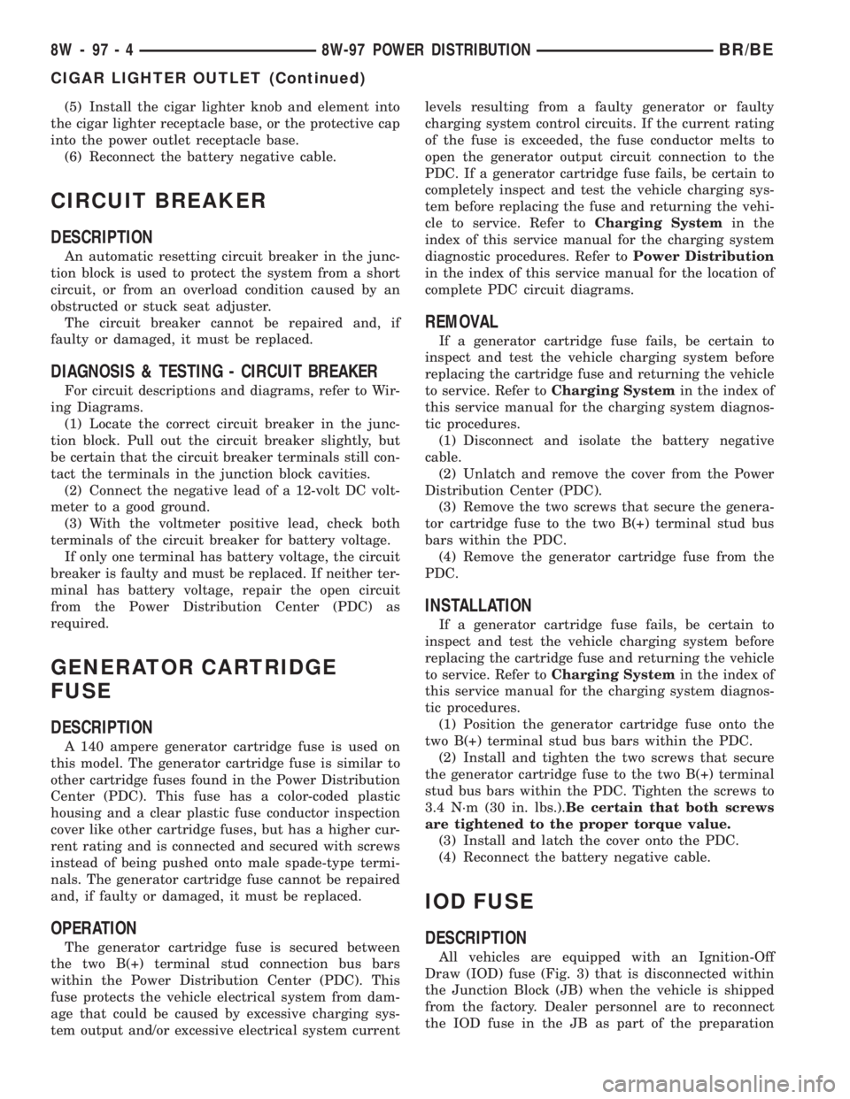
GENERATOR CARTRIDGE
FUSE
DESCRIPTION
A 140 ampere generator cartridge fuse is used on
this model. The generator cartridge fuse is similar to
other cartridge fuses found in the Power Distribution
Center (PDC). This fuse has a color-coded plastic
housing and a clear plastic fuse conductor inspection
cover like other cartridge fuses, but has a higher cur-
rent rating and is connected and secured with screws
instead of being pushed onto male spade-type termi-
nals. The generator cartridge fuse cannot be repaired
and, if faulty or damaged, it must be replaced.
OPERATION
The generator cartridge fuse is secured between
the two B(+) terminal stud connection bus bars
within the Power Distribution Center (PDC). This
fuse protects the vehicle electrical system from dam-
age that could be caused by excessive charging sys-
tem output and/or excessive electrical system currentlevels resulting from a faulty generator or faulty
charging system control circuits. If the current rating
of the fuse is exceeded, the fuse conductor melts to
open the generator output circuit connection to the
PDC. If a generator cartridge fuse fails, be certain to
completely inspect and test the vehicle charging sys-
tem before replacing the fuse and returning the vehi-
cle to service. Refer toCharging Systemin the
index of this service manual for the charging system
diagnostic procedures. Refer toPower Distribution
in the index of this service manual for the location of
complete PDC circuit diagrams.
REMOVAL
If a generator cartridge fuse fails, be certain to
inspect and test the vehicle charging system before
replacing the cartridge fuse and returning the vehicle
to service. Refer toCharging Systemin the index of
this service manual for the charging system diagnos-
tic procedures.
(1) Disconnect and isolate the battery negative
cable.
(2) Unlatch and remove the cover from the Power
Distribution Center (PDC).
(3) Remove the two screws that secure the genera-
tor cartridge fuse to the two B(+) terminal stud bus
bars within the PDC.
(4) Remove the generator cartridge fuse from the
PDC.
INSTALLATION
If a generator cartridge fuse fails, be certain to
inspect and test the vehicle charging system before
replacing the cartridge fuse and returning the vehicle
to service. Refer toCharging Systemin the index of
this service manual for the charging system diagnos-
tic procedures.
(1) Position the generator cartridge fuse onto the
two B(+) terminal stud bus bars within the PDC.
(2) Install and tighten the two screws that secure
the generator cartridge fuse to the two B(+) terminal
stud bus bars within the PDC. Tighten the screws to
3.4 N´m (30 in. lbs.).Be certain that both screws
are tightened to the proper torque value.
(3) Install and latch the cover onto the PDC.
(4) Reconnect the battery negative cable.
IOD FUSE
DESCRIPTION
All vehicles are equipped with an Ignition-Off
Draw (IOD) fuse (Fig. 3) that is disconnected within
the Junction Block (JB) when the vehicle is shipped
from the factory. Dealer personnel are to reconnect
the IOD fuse in the JB as part of the preparation
8W - 97 - 4 8W-97 POWER DISTRIBUTIONBR/BE
CIGAR LIGHTER OUTLET (Continued)
Page 1151 of 2889
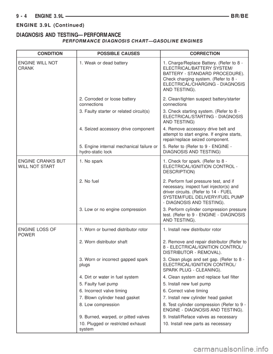
DIAGNOSIS AND TESTINGÐPERFORMANCE
PERFORMANCE DIAGNOSIS CHARTÐGASOLINE ENGINES
CONDITION POSSIBLE CAUSES CORRECTION
ENGINE WILL NOT
CRANK1. Weak or dead battery 1. Charge/Replace Battery. (Refer to 8 -
ELECTRICAL/BATTERY SYSTEM/
BATTERY - STANDARD PROCEDURE).
Check charging system. (Refer to 8 -
ELECTRICAL/CHARGING - DIAGNOSIS
AND TESTING).
2. Corroded or loose battery
connections2. Clean/tighten suspect battery/starter
connections
3. Faulty starter or related circuit(s) 3. Check starting system. (Refer to 8 -
ELECTRICAL/STARTING - DIAGNOSIS
AND TESTING)
4. Seized accessory drive component 4. Remove accessory drive belt and
attempt to start engine. If engine starts,
repair/replace seized component.
5. Engine internal mechanical failure or
hydro-static lock5. Refer to (Refer to 9 - ENGINE -
DIAGNOSIS AND TESTING)
ENGINE CRANKS BUT
WILL NOT START1. No spark 1. Check for spark. (Refer to 8 -
ELECTRICAL/IGNITION CONTROL -
DESCRIPTION)
2. No fuel 2. Perform fuel pressure test, and if
necessary, inspect fuel injector(s) and
driver circuits. (Refer to 14 - FUEL
SYSTEM/FUEL DELIVERY/FUEL PUMP
- DIAGNOSIS AND TESTING).
3. Low or no engine compression 3. Perform cylinder compression pressure
test. (Refer to 9 - ENGINE - DIAGNOSIS
AND TESTING).
ENGINE LOSS OF
POWER1. Worn or burned distributor rotor 1. Install new distributor rotor
2. Worn distributor shaft 2. Remove and repair distributor (Refer to
8 - ELECTRICAL/IGNITION CONTROL/
DISTRIBUTOR - REMOVAL).
3. Worn or incorrect gapped spark
plugs3. Clean plugs and set gap. (Refer to 8 -
ELECTRICAL/IGNITION CONTROL/
SPARK PLUG - CLEANING).
4. Dirt or water in fuel system 4. Clean system and replace fuel filter
5. Faulty fuel pump 5. Install new fuel pump
6. Incorrect valve timing 6. Correct valve timing
7. Blown cylinder head gasket 7. Install new cylinder head gasket
8. Low compression 8. Test cylinder compression (Refer to 9 -
ENGINE - DIAGNOSIS AND TESTING).
9. Burned, warped, or pitted valves 9. Install/Reface valves as necessary
10. Plugged or restricted exhaust
system10. Install new parts as necessary
9 - 4 ENGINE 3.9LBR/BE
ENGINE 3.9L (Continued)