2001 DODGE RAM battery location
[x] Cancel search: battery locationPage 492 of 2889
rosion or foreign material, then reassembled.
Following reassembly, check the voltage drop for the
battery cable connection and the battery cable again
to confirm repair.
When performing the voltage drop test, it is impor-
tant to remember that the voltage drop is giving an
indication of the resistance between the two points at
which the voltmeter probes are attached.EXAM-
PLE:When testing the resistance of the battery pos-
itive cable, touch the voltmeter leads to the battery
positive cable terminal clamp and to the battery pos-
itive cable eyelet terminal at the starter solenoid
B(+) terminal stud. If you probe the battery positive
terminal post and the battery positive cable eyelet
terminal at the starter solenoid B(+) terminal stud,
you are reading the combined voltage drop in the
battery positive cable terminal clamp-to-terminal
post connection and the battery positive cable.
VOLTAGE DROP TEST
WARNING: IF THE BATTERY SHOWS SIGNS OF
FREEZING, LEAKING, LOOSE POSTS, OR LOW
ELECTROLYTE LEVEL, DO NOT TEST, ASSIST-
BOOST, OR CHARGE. THE BATTERY MAY ARC
INTERNALLY AND EXPLODE. PERSONAL INJURY
AND/OR VEHICLE DAMAGE MAY RESULT.
WARNING: EXPLOSIVE HYDROGEN GAS FORMS IN
AND AROUND THE BATTERY. DO NOT SMOKE,
USE FLAME, OR CREATE SPARKS NEAR THE BAT-
TERY. PERSONAL INJURY AND/OR VEHICLE DAM-
AGE MAY RESULT.
WARNING: THE BATTERY CONTAINS SULFURIC
ACID, WHICH IS POISONOUS AND CAUSTIC. AVOID
CONTACT WITH THE SKIN, EYES, OR CLOTHING.
IN THE EVENT OF CONTACT, FLUSH WITH WATER
AND CALL A PHYSICIAN IMMEDIATELY. KEEP OUT
OF THE REACH OF CHILDREN.
WARNING: IF THE BATTERY IS EQUIPPED WITH
REMOVABLE CELL CAPS, BE CERTAIN THAT EACH
OF THE CELL CAPS IS IN PLACE AND TIGHT
BEFORE THE BATTERY IS RETURNED TO SER-
VICE. PERSONAL INJURY AND/OR VEHICLE DAM-
AGE MAY RESULT FROM LOOSE OR MISSING
CELL CAPS.
WARNING: MODELS EQUIPPED WITH THE DIESEL
ENGINE OPTION ALSO HAVE AN AUTOMATIC
SHUTDOWN (ASD) RELAY LOCATED IN THE
POWER DISTRIBUTION CENTER (PDC), IN THE
ENGINE COMPARTMENT. HOWEVER, REMOVAL OFTHE ASD RELAY MAY NOT PREVENT THE DIESEL
ENGINE FROM STARTING. BE CERTAIN TO ALSO
DISCONNECT THE FUEL SHUTDOWN SOLENOID
WIRE HARNESS CONNECTOR ON MODELS WITH A
DIESEL ENGINE. FAILURE TO DO SO MAY RESULT
IN PERSONAL INJURY.
The following operation will require a voltmeter
accurate to 1/10 (0.10) volt. Before performing this
test, be certain that the following procedures are
accomplished:
²The battery is fully-charged and load tested.
Refer toBattery Chargingin the index of this ser-
vice manual for the location of the proper battery
charging procedures. Refer toBatteryin the index of
this service manual for the location of the battery
diagnosis and testing procedures, including the
proper battery load test procedures.
²Fully engage the parking brake.
²If the vehicle is equipped with an automatic
transmission, place the gearshift selector lever in the
Park position. If the vehicle is equipped with a man-
ual transmission, place the gearshift selector lever in
the Neutral position and block the clutch pedal in the
fully depressed position.
²Verify that all lamps and accessories are turned
off.
²To prevent a gasoline engine from starting,
remove the Automatic ShutDown (ASD) relay. The
ASD relay is located in the Power Distribution Cen-
ter (PDC), in the engine compartment. See the fuse
and relay layout label affixed to the underside of the
PDC cover for ASD relay identification and location.
To prevent a diesel engine from starting, disconnect
the fuel shutdown solenoid wire harness connector
(Fig. 21).
(1) Connect the positive lead of the voltmeter to
the battery negative terminal post. Connect the neg-
ative lead of the voltmeter to the battery negative
cable terminal clamp (Fig. 22). Rotate and hold the
ignition switch in the Start position. Observe the
voltmeter. If voltage is detected, correct the poor con-
nection between the battery negative cable terminal
clamp and the battery negative terminal post.
NOTE: If the vehicle is equipped with a dual battery
system, Step 1 must be performed twice, once for
each battery.
(2) Connect the positive lead of the voltmeter to
the battery positive terminal post. Connect the nega-
tive lead of the voltmeter to the battery positive cable
terminal clamp (Fig. 23). Rotate and hold the ignition
switch in the Start position. Observe the voltmeter. If
voltage is detected, correct the poor connection
between the battery positive cable terminal clamp
and the battery positive terminal post.
BR/BEBATTERY SYSTEM 8F - 21
BATTERY CABLE (Continued)
Page 495 of 2889
NEGATIVE CABLE INSTALLATION - GASOLINE
(1) Position the battery wire harness into the
engine compartment and under the compressor
mounting bracket, if equipped.
(2) Install and tighten the nut that secures the
battery negative cable ground eyelet terminal to the
stud on the power steering pump pivot bolt.
(3) Install the generator output cable eyelet termi-
nal onto the generator output terminal stud.
(4) Install and tighten the nut that secures the
generator output cable eyelet terminal to the genera-
tor output terminal stud. Tighten the nut to 8.4 N´m
(75 in. lbs.).
(5) Position the cover for the generator output ter-
minal stud housing onto the back of the generator
and snap it into place.
(6) Secure wire assembly in place with pushpin
retainers in there original positions.
(7) Install and tighten the screw that secures the
battery negative cable eyelet terminal to the radiator
closure panel, near the battery. Tighten the screw to
40 in. lbs.
(8) Install and tighten the screw that secures the
battery negative cable eyelet terminal to the left
front side of the frame assembly. Tighten the screw
to 80 in. lbs.
(9) Install and tighten the nut that secures the
battery positive cable eyelet terminal and the gener-
ator output cable eyelet terminal to the PDC B(+)
terminal stud. Tighten the nut to 80 in. lbs.
(10) Reconnect the battery negative cable terminal
clamp to the battery negative terminal post. Tighten
the terminal clamp pinch-bolt hex nut to 35 in. lbs.
(11)
Apply a thin coating of petroleum jelly or chassis
grease to the exposed surfaces of the battery cable ter-
minal clamps and the battery terminal posts.
BATTERY TRAY
DESCRIPTION
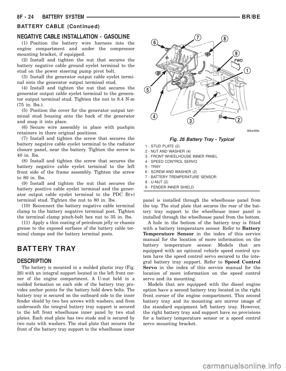
The battery is mounted in a molded plastic tray (Fig.
26) with an integral support located in the left front cor-
ner of the engine compartment. A U-nut held in a
molded formation on each side of the battery tray pro-
vides anchor points for the battery hold down bolts. The
battery tray is secured on the outboard side to the inner
fender shield by two hex screws with washers, and from
underneath the integral battery tray support is secured
to the left front wheelhouse inner panel by two stud
plates. Each stud plate has two studs and is secured by
two nuts with washers. The stud plate that secures the
front of the battery tray support to the wheelhouse innerpanel is installed through the wheelhouse panel from
the top. The stud plate that secures the rear of the bat-
tery tray support to the wheelhouse inner panel is
installed through the wheelhouse panel from the bottom.
A hole in the bottom of the battery tray is fitted
with a battery temperature sensor. Refer toBattery
Temperature Sensorin the index of this service
manual for the location of more information on the
battery temperature sensor. Models that are
equipped with an optional vehicle speed control sys-
tem have the speed control servo secured to the inte-
gral battery tray support. Refer toSpeed Control
Servoin the index of this service manual for the
location of more information on the speed control
servo and its mounting.
Models that are equipped with the diesel engine
option have a second battery tray located in the right
front corner of the engine compartment. This second
battery tray and its mounting are mirror image of
the standard equipment left battery tray. However,
the right battery tray and support have no provisions
for a battery temperature sensor or a speed control
servo mounting bracket.
Fig. 26 Battery Tray - Typical
1 - STUD PLATE (2)
2 - NUT AND WASHER (4)
3 - FRONT WHEELHOUSE INNER PANEL
4 - SPEED CONTROL SERVO
5 - TRAY
6 - SCREW AND WASHER (2)
7 - BATTERY TREMPERATURE SENSOR
8 - U-NUT (2)
9 - FENDER INNER SHIELD
8F - 24 BATTERY SYSTEMBR/BE
BATTERY CABLE (Continued)
Page 496 of 2889
OPERATION
The battery tray provides a secure mounting loca-
tion and supports the battery. On some vehicles, the
battery tray also provides the anchor point/s for the
battery holddown hardware. The battery tray and
the battery holddown hardware combine to secure
and stabilize the battery in the engine compartment,
which prevents battery movement during vehicle
operation. Unrestrained battery movement during
vehicle operation could result in damage to the vehi-
cle, the battery, or both.
REMOVAL
(1) Remove the battery from the battery tray.
Refer toBatteryin this group for the location of the
proper battery removal procedure.
(2) If the left battery tray is being removed,
remove the battery temperature sensor from the left
battery tray. Refer toBattery Temperature Sensor
in the index of this service manual for the location of
the proper battery temperature sensor removal pro-
cedures.
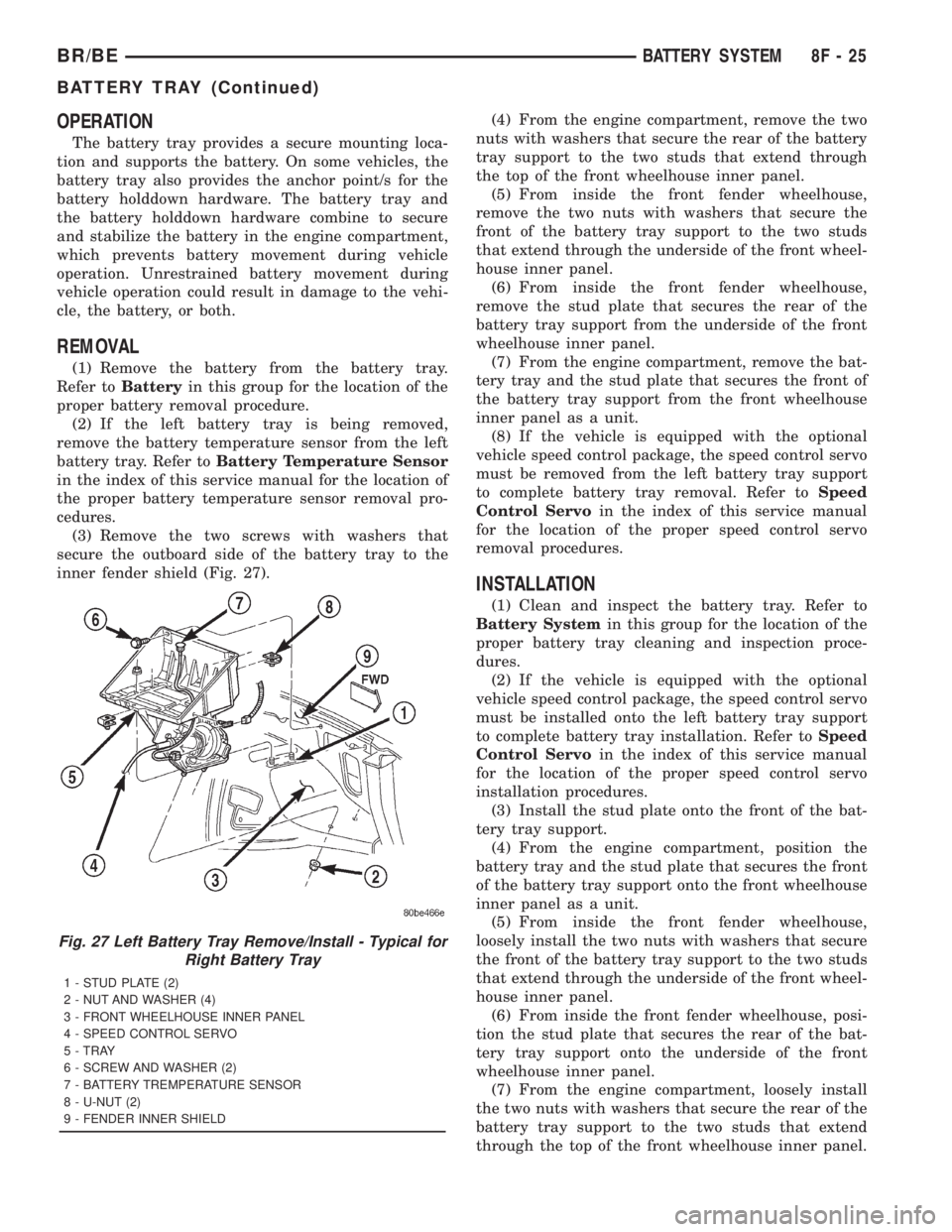
(3) Remove the two screws with washers that
secure the outboard side of the battery tray to the
inner fender shield (Fig. 27).(4) From the engine compartment, remove the two
nuts with washers that secure the rear of the battery
tray support to the two studs that extend through
the top of the front wheelhouse inner panel.
(5) From inside the front fender wheelhouse,
remove the two nuts with washers that secure the
front of the battery tray support to the two studs
that extend through the underside of the front wheel-
house inner panel.
(6) From inside the front fender wheelhouse,
remove the stud plate that secures the rear of the
battery tray support from the underside of the front
wheelhouse inner panel.
(7) From the engine compartment, remove the bat-
tery tray and the stud plate that secures the front of
the battery tray support from the front wheelhouse
inner panel as a unit.
(8) If the vehicle is equipped with the optional
vehicle speed control package, the speed control servo
must be removed from the left battery tray support
to complete battery tray removal. Refer toSpeed
Control Servoin the index of this service manual
for the location of the proper speed control servo
removal procedures.
INSTALLATION
(1) Clean and inspect the battery tray. Refer to
Battery Systemin this group for the location of the
proper battery tray cleaning and inspection proce-
dures.
(2) If the vehicle is equipped with the optional
vehicle speed control package, the speed control servo
must be installed onto the left battery tray support
to complete battery tray installation. Refer toSpeed
Control Servoin the index of this service manual
for the location of the proper speed control servo
installation procedures.
(3) Install the stud plate onto the front of the bat-
tery tray support.
(4) From the engine compartment, position the
battery tray and the stud plate that secures the front
of the battery tray support onto the front wheelhouse
inner panel as a unit.
(5) From inside the front fender wheelhouse,
loosely install the two nuts with washers that secure
the front of the battery tray support to the two studs
that extend through the underside of the front wheel-
house inner panel.
(6) From inside the front fender wheelhouse, posi-
tion the stud plate that secures the rear of the bat-
tery tray support onto the underside of the front
wheelhouse inner panel.
(7) From the engine compartment, loosely install
the two nuts with washers that secure the rear of the
battery tray support to the two studs that extend
through the top of the front wheelhouse inner panel.
Fig. 27 Left Battery Tray Remove/Install - Typical for
Right Battery Tray
1 - STUD PLATE (2)
2 - NUT AND WASHER (4)
3 - FRONT WHEELHOUSE INNER PANEL
4 - SPEED CONTROL SERVO
5 - TRAY
6 - SCREW AND WASHER (2)
7 - BATTERY TREMPERATURE SENSOR
8 - U-NUT (2)
9 - FENDER INNER SHIELD
BR/BEBATTERY SYSTEM 8F - 25
BATTERY TRAY (Continued)
Page 497 of 2889

(8) Install and tighten the two screws with wash-
ers that secure the outboard side of the battery tray
to the inner fender shield. Tighten the screws to 15.8
N´m (140 in. lbs.).
(9) Final tighten the four nuts with washers that
secure the battery tray support to the stud plates on
the front wheelhouse inner panel. Tighten the nuts
to 15.8 N´m (140 in. lbs.).(10) If the left battery tray is being installed,
install the battery temperature sensor onto the left
battery tray. Refer toBattery Temperature Sensor
in the index of this service manual for the location of
the proper battery temperature sensor installation
procedures.
(11) Install the battery onto the battery tray. Refer
toBatteryin this group for the location of the
proper battery installation procedures.
8F - 26 BATTERY SYSTEMBR/BE
BATTERY TRAY (Continued)
Page 500 of 2889
BATTERY TEMPERATURE
SENSOR
DESCRIPTION
The Battery Temperature Sensor (BTS) is attached
to the battery tray located under the battery.
OPERATION
The BTS is used to determine the battery temper-
ature and control battery charging rate. This temper-
ature data, along with data from monitored line
voltage, is used by the PCM to vary the battery
charging rate. System voltage will be higher at colder
temperatures and is gradually reduced at warmer
temperatures.
The PCM sends 5 volts to the sensor and is
grounded through the sensor return line. As temper-
ature increases, resistance in the sensor decreases
and the detection voltage at the PCM increases.
The BTS is also used for OBD II diagnostics. Cer-
tain faults and OBD II monitors are either enabled
or disabled, depending upon BTS input (for example,
disable purge and enable Leak Detection Pump
(LDP) and O2 sensor heater tests). Most OBD II
monitors are disabled below 20ÉF.
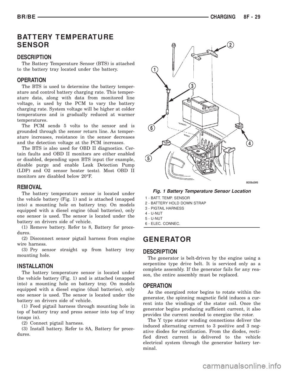
REMOVAL
The battery temperature sensor is located under
the vehicle battery (Fig. 1) and is attached (snapped
into) a mounting hole on battery tray. On models
equipped with a diesel engine (dual batteries), only
one sensor is used. The sensor is located under the
battery on drivers side of vehicle.
(1) Remove battery. Refer to 8, Battery for proce-
dures.
(2) Disconnect sensor pigtail harness from engine
wire harness.
(3) Pry sensor straight up from battery tray
mounting hole.
INSTALLATION
The battery temperature sensor is located under
the vehicle battery (Fig. 1) and is attached (snapped
into) a mounting hole on battery tray. On models
equipped with a diesel engine (dual batteries), only
one sensor is used. The sensor is located under the
battery on drivers side of vehicle.
(1) Feed pigtail harness through mounting hole in
top of battery tray and press sensor into top of tray
(snaps in).
(2) Connect pigtail harness.
(3) Install battery. Refer to 8A, Battery for proce-
dures.
GENERATOR
DESCRIPTION
The generator is belt-driven by the engine using a
serpentine type drive belt. It is serviced only as a
complete assembly. If the generator fails for any rea-
son, the entire assembly must be replaced.
OPERATION
As the energized rotor begins to rotate within the
generator, the spinning magnetic field induces a cur-
rent into the windings of the stator coil. Once the
generator begins producing sufficient current, it also
provides the current needed to energize the rotor.
The Y type stator winding connections deliver the
induced alternating current to 3 positive and 3 neg-
ative diodes for rectification. From the diodes, recti-
fied direct current is delivered to the vehicle
electrical system through the generator battery ter-
minal.
Fig. 1 Battery Temperature Sensor Location
1 - BATT. TEMP. SENSOR
2 - BATTERY HOLD DOWN STRAP
3 - PIGTAIL HARNESS
4 - U-NUT
5 - U-NUT
6 - ELEC. CONNEC.
BR/BECHARGING 8F - 29
Page 506 of 2889
(4) Verify that all lamps and accessories are
turned off.
(5) To prevent a gasoline engine from starting,
remove Automatic ShutDown (ASD) relay. To prevent
a diesel engine from starting, remove Fuel Pump
Relay. These relays are located in Power Distribution
Center (PDC). Refer to label on PDC cover for relay
location.
WARNING: IF EQUIPPED WITH DIESEL ENGINE,
ATTEMPT TO START ENGINE A FEW TIMES
BEFORE PROCEEDING WITH FOLLOWING STEP.
(6) Rotate and hold ignition switch in Start posi-
tion. Note cranking voltage and current (amperage)
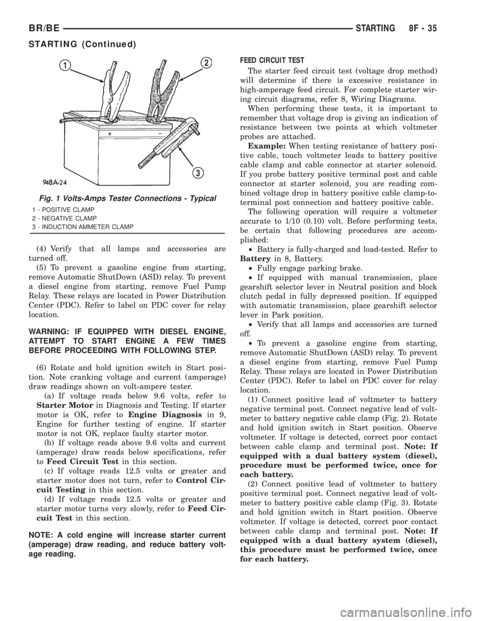
draw readings shown on volt-ampere tester.
(a) If voltage reads below 9.6 volts, refer to
Starter Motorin Diagnosis and Testing. If starter
motor is OK, refer toEngine Diagnosisin 9,
Engine for further testing of engine. If starter
motor is not OK, replace faulty starter motor.
(b) If voltage reads above 9.6 volts and current
(amperage) draw reads below specifications, refer
toFeed Circuit Testin this section.
(c) If voltage reads 12.5 volts or greater and
starter motor does not turn, refer toControl Cir-
cuit Testingin this section.
(d) If voltage reads 12.5 volts or greater and
starter motor turns very slowly, refer toFeed Cir-
cuit Testin this section.
NOTE: A cold engine will increase starter current
(amperage) draw reading, and reduce battery volt-
age reading.FEED CIRCUIT TEST
The starter feed circuit test (voltage drop method)
will determine if there is excessive resistance in
high-amperage feed circuit. For complete starter wir-
ing circuit diagrams, refer 8, Wiring Diagrams.
When performing these tests, it is important to
remember that voltage drop is giving an indication of
resistance between two points at which voltmeter
probes are attached.
Example:When testing resistance of battery posi-
tive cable, touch voltmeter leads to battery positive
cable clamp and cable connector at starter solenoid.
If you probe battery positive terminal post and cable
connector at starter solenoid, you are reading com-
bined voltage drop in battery positive cable clamp-to-
terminal post connection and battery positive cable.
The following operation will require a voltmeter
accurate to 1/10 (0.10) volt. Before performing tests,
be certain that following procedures are accom-
plished:
²Battery is fully-charged and load-tested. Refer to
Batteryin 8, Battery.
²Fully engage parking brake.
²If equipped with manual transmission, place
gearshift selector lever in Neutral position and block
clutch pedal in fully depressed position. If equipped
with automatic transmission, place gearshift selector
lever in Park position.
²Verify that all lamps and accessories are turned
off.
²To prevent a gasoline engine from starting,
remove Automatic ShutDown (ASD) relay. To prevent
a diesel engine from starting, remove Fuel Pump
Relay. These relays are located in Power Distribution
Center (PDC). Refer to label on PDC cover for relay
location.
(1) Connect positive lead of voltmeter to battery
negative terminal post. Connect negative lead of volt-
meter to battery negative cable clamp (Fig. 2). Rotate
and hold ignition switch in Start position. Observe
voltmeter. If voltage is detected, correct poor contact
between cable clamp and terminal post.Note: If
equipped with a dual battery system (diesel),
procedure must be performed twice, once for
each battery.
(2) Connect positive lead of voltmeter to battery
positive terminal post. Connect negative lead of volt-
meter to battery positive cable clamp (Fig. 3). Rotate
and hold ignition switch in Start position. Observe
voltmeter. If voltage is detected, correct poor contact
between cable clamp and terminal post.Note: If
equipped with a dual battery system (diesel),
this procedure must be performed twice, once
for each battery.
Fig. 1 Volts-Amps Tester Connections - Typical
1 - POSITIVE CLAMP
2 - NEGATIVE CLAMP
3 - INDUCTION AMMETER CLAMP
BR/BESTARTING 8F - 35
STARTING (Continued)
Page 513 of 2889
5.9L DIESEL ENGINE
(1) If equipped, position aluminum spacer to rear
of starter.
(2) Position starter motor to engine.
(3) Support starter and loosely install three
mounting bolts.
(4) Tighten 3 bolts to 43.4 N´m (32 ft. lbs.).
(5) Position wiring eyelets to starter studs and
install nuts. Tighten small nut to 6.2 N´m (55 in.
lbs.). Tighten large nut to 13.6 N´m (120 in. lbs.).
(6) Install protective rubber boot over stud.
(7) Lower vehicle.
(8) Connect battery cables to both batteries.
8.0L GASOLINE ENGINE
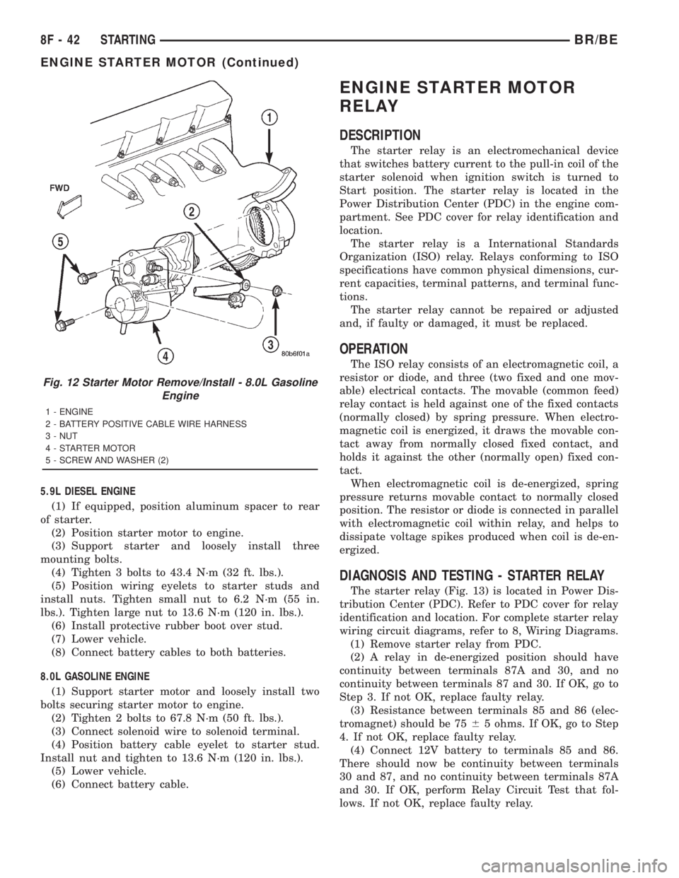
(1) Support starter motor and loosely install two
bolts securing starter motor to engine.
(2) Tighten 2 bolts to 67.8 N´m (50 ft. lbs.).
(3) Connect solenoid wire to solenoid terminal.
(4) Position battery cable eyelet to starter stud.
Install nut and tighten to 13.6 N´m (120 in. lbs.).
(5) Lower vehicle.
(6) Connect battery cable.
ENGINE STARTER MOTOR
RELAY
DESCRIPTION
The starter relay is an electromechanical device
that switches battery current to the pull-in coil of the
starter solenoid when ignition switch is turned to
Start position. The starter relay is located in the
Power Distribution Center (PDC) in the engine com-
partment. See PDC cover for relay identification and
location.
The starter relay is a International Standards
Organization (ISO) relay. Relays conforming to ISO
specifications have common physical dimensions, cur-
rent capacities, terminal patterns, and terminal func-
tions.
The starter relay cannot be repaired or adjusted
and, if faulty or damaged, it must be replaced.
OPERATION
The ISO relay consists of an electromagnetic coil, a
resistor or diode, and three (two fixed and one mov-
able) electrical contacts. The movable (common feed)
relay contact is held against one of the fixed contacts
(normally closed) by spring pressure. When electro-
magnetic coil is energized, it draws the movable con-
tact away from normally closed fixed contact, and
holds it against the other (normally open) fixed con-
tact.
When electromagnetic coil is de-energized, spring
pressure returns movable contact to normally closed
position. The resistor or diode is connected in parallel
with electromagnetic coil within relay, and helps to
dissipate voltage spikes produced when coil is de-en-
ergized.
DIAGNOSIS AND TESTING - STARTER RELAY
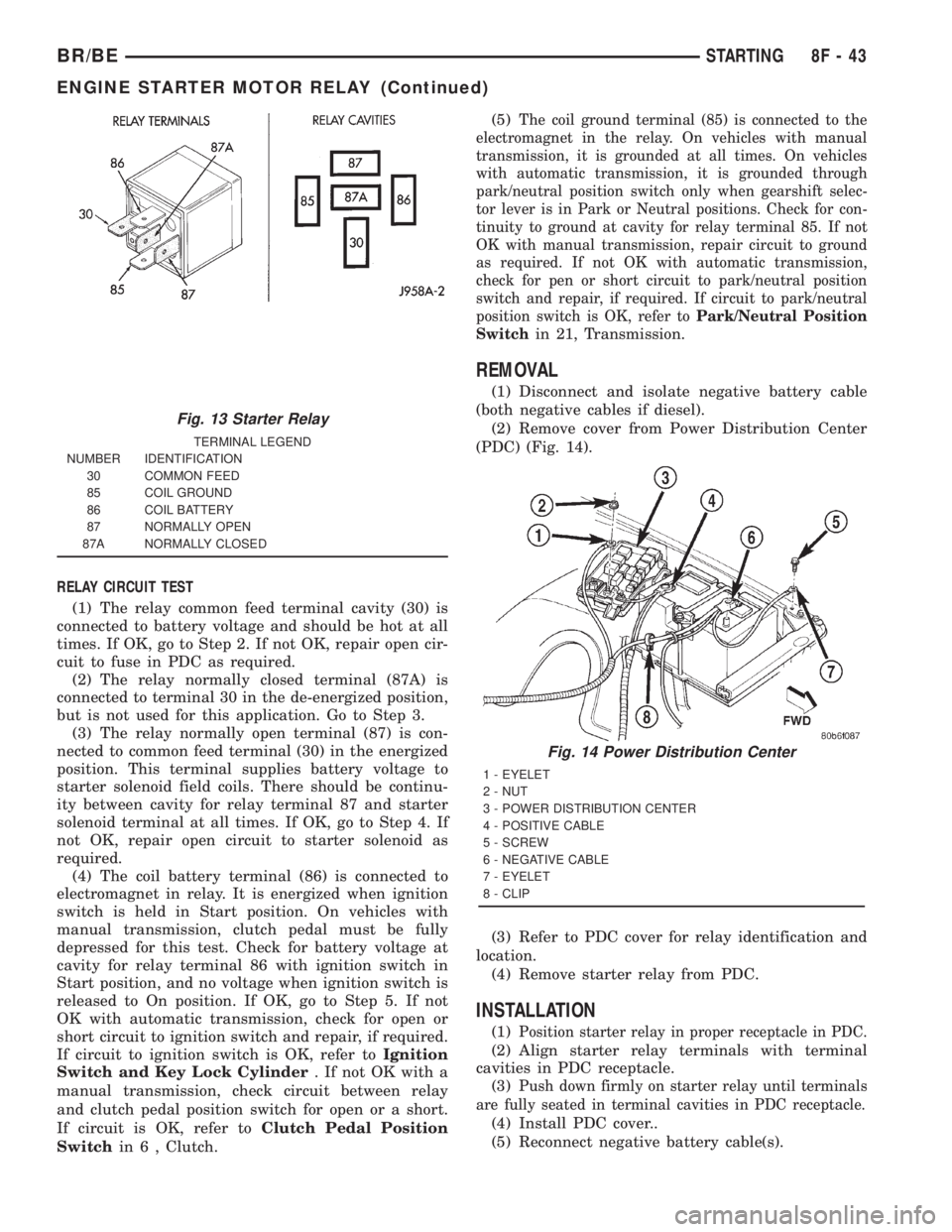
The starter relay (Fig. 13) is located in Power Dis-
tribution Center (PDC). Refer to PDC cover for relay
identification and location. For complete starter relay
wiring circuit diagrams, refer to 8, Wiring Diagrams.
(1) Remove starter relay from PDC.
(2) A relay in de-energized position should have
continuity between terminals 87A and 30, and no
continuity between terminals 87 and 30. If OK, go to
Step 3. If not OK, replace faulty relay.
(3) Resistance between terminals 85 and 86 (elec-
tromagnet) should be 7565 ohms. If OK, go to Step
4. If not OK, replace faulty relay.
(4) Connect 12V battery to terminals 85 and 86.
There should now be continuity between terminals
30 and 87, and no continuity between terminals 87A
and 30. If OK, perform Relay Circuit Test that fol-
lows. If not OK, replace faulty relay.
Fig. 12 Starter Motor Remove/Install - 8.0L Gasoline
Engine
1 - ENGINE
2 - BATTERY POSITIVE CABLE WIRE HARNESS
3 - NUT
4 - STARTER MOTOR
5 - SCREW AND WASHER (2)
8F - 42 STARTINGBR/BE
ENGINE STARTER MOTOR (Continued)
Page 514 of 2889
RELAY CIRCUIT TEST
(1) The relay common feed terminal cavity (30) is
connected to battery voltage and should be hot at all
times. If OK, go to Step 2. If not OK, repair open cir-
cuit to fuse in PDC as required.
(2) The relay normally closed terminal (87A) is
connected to terminal 30 in the de-energized position,
but is not used for this application. Go to Step 3.
(3) The relay normally open terminal (87) is con-
nected to common feed terminal (30) in the energized
position. This terminal supplies battery voltage to
starter solenoid field coils. There should be continu-
ity between cavity for relay terminal 87 and starter
solenoid terminal at all times. If OK, go to Step 4. If
not OK, repair open circuit to starter solenoid as
required.
(4) The coil battery terminal (86) is connected to
electromagnet in relay. It is energized when ignition
switch is held in Start position. On vehicles with
manual transmission, clutch pedal must be fully
depressed for this test. Check for battery voltage at
cavity for relay terminal 86 with ignition switch in
Start position, and no voltage when ignition switch is
released to On position. If OK, go to Step 5. If not
OK with automatic transmission, check for open or
short circuit to ignition switch and repair, if required.
If circuit to ignition switch is OK, refer toIgnition
Switch and Key Lock Cylinder. If not OK with a
manual transmission, check circuit between relay
and clutch pedal position switch for open or a short.
If circuit is OK, refer toClutch Pedal Position
Switchin 6 , Clutch.(5)
The coil ground terminal (85) is connected to the
electromagnet in the relay. On vehicles with manual
transmission, it is grounded at all times. On vehicles
with automatic transmission, it is grounded through
park/neutral position switch only when gearshift selec-
tor lever is in Park or Neutral positions. Check for con-
tinuity to ground at cavity for relay terminal 85. If not
OK with manual transmission, repair circuit to ground
as required. If not OK with automatic transmission,
check for pen or short circuit to park/neutral position
switch and repair, if required. If circuit to park/neutral
position switch is OK, refer toPark/Neutral Position
Switch
in 21, Transmission.
REMOVAL
(1) Disconnect and isolate negative battery cable
(both negative cables if diesel).
(2) Remove cover from Power Distribution Center
(PDC) (Fig. 14).
(3) Refer to PDC cover for relay identification and
location.
(4) Remove starter relay from PDC.
INSTALLATION
(1)Position starter relay in proper receptacle in PDC.
(2) Align starter relay terminals with terminal
cavities in PDC receptacle.
(3)
Push down firmly on starter relay until terminals
are fully seated in terminal cavities in PDC receptacle.
(4) Install PDC cover..
(5) Reconnect negative battery cable(s).
Fig. 13 Starter Relay
TERMINAL LEGEND
NUMBER IDENTIFICATION
30 COMMON FEED
85 COIL GROUND
86 COIL BATTERY
87 NORMALLY OPEN
87A NORMALLY CLOSED
Fig. 14 Power Distribution Center
1 - EYELET
2 - NUT
3 - POWER DISTRIBUTION CENTER
4 - POSITIVE CABLE
5 - SCREW
6 - NEGATIVE CABLE
7 - EYELET
8 - CLIP
BR/BESTARTING 8F - 43
ENGINE STARTER MOTOR RELAY (Continued)