2001 DODGE RAM battery location
[x] Cancel search: battery locationPage 435 of 2889
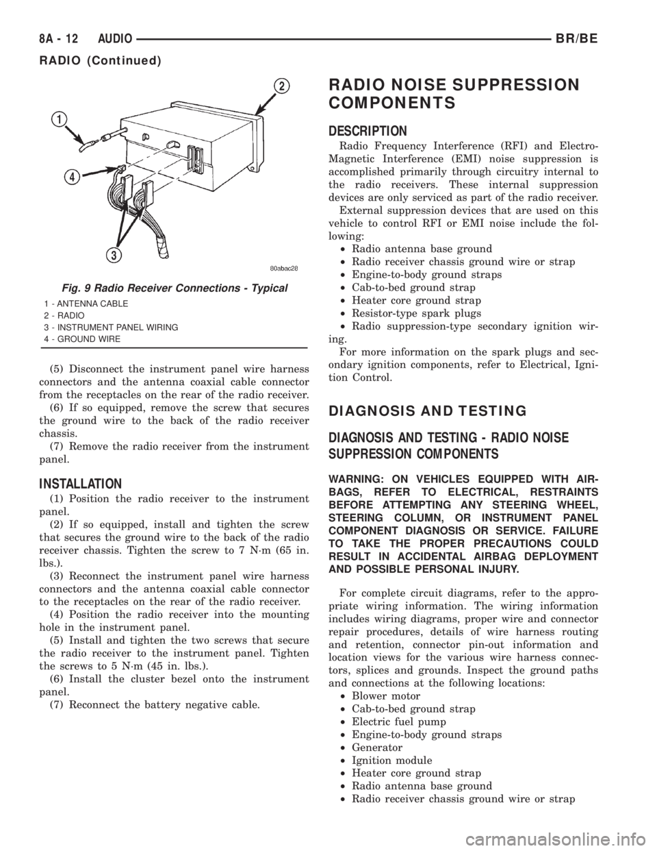
(5) Disconnect the instrument panel wire harness
connectors and the antenna coaxial cable connector
from the receptacles on the rear of the radio receiver.
(6) If so equipped, remove the screw that secures
the ground wire to the back of the radio receiver
chassis.
(7) Remove the radio receiver from the instrument
panel.
INSTALLATION
(1) Position the radio receiver to the instrument
panel.
(2) If so equipped, install and tighten the screw
that secures the ground wire to the back of the radio
receiver chassis. Tighten the screw to 7 N´m (65 in.
lbs.).
(3) Reconnect the instrument panel wire harness
connectors and the antenna coaxial cable connector
to the receptacles on the rear of the radio receiver.
(4) Position the radio receiver into the mounting
hole in the instrument panel.
(5) Install and tighten the two screws that secure
the radio receiver to the instrument panel. Tighten
the screws to 5 N´m (45 in. lbs.).
(6) Install the cluster bezel onto the instrument
panel.
(7) Reconnect the battery negative cable.
RADIO NOISE SUPPRESSION
COMPONENTS
DESCRIPTION
Radio Frequency Interference (RFI) and Electro-
Magnetic Interference (EMI) noise suppression is
accomplished primarily through circuitry internal to
the radio receivers. These internal suppression
devices are only serviced as part of the radio receiver.
External suppression devices that are used on this
vehicle to control RFI or EMI noise include the fol-
lowing:
²Radio antenna base ground
²Radio receiver chassis ground wire or strap
²Engine-to-body ground straps
²Cab-to-bed ground strap
²Heater core ground strap
²Resistor-type spark plugs
²Radio suppression-type secondary ignition wir-
ing.
For more information on the spark plugs and sec-
ondary ignition components, refer to Electrical, Igni-
tion Control.
DIAGNOSIS AND TESTING
DIAGNOSIS AND TESTING - RADIO NOISE
SUPPRESSION COMPONENTS
WARNING: ON VEHICLES EQUIPPED WITH AIR-
BAGS, REFER TO ELECTRICAL, RESTRAINTS
BEFORE ATTEMPTING ANY STEERING WHEEL,
STEERING COLUMN, OR INSTRUMENT PANEL
COMPONENT DIAGNOSIS OR SERVICE. FAILURE
TO TAKE THE PROPER PRECAUTIONS COULD
RESULT IN ACCIDENTAL AIRBAG DEPLOYMENT
AND POSSIBLE PERSONAL INJURY.
For complete circuit diagrams, refer to the appro-
priate wiring information. The wiring information
includes wiring diagrams, proper wire and connector
repair procedures, details of wire harness routing
and retention, connector pin-out information and
location views for the various wire harness connec-
tors, splices and grounds. Inspect the ground paths
and connections at the following locations:
²Blower motor
²Cab-to-bed ground strap
²Electric fuel pump
²Engine-to-body ground straps
²Generator
²Ignition module
²Heater core ground strap
²Radio antenna base ground
²Radio receiver chassis ground wire or strap
Fig. 9 Radio Receiver Connections - Typical
1 - ANTENNA CABLE
2 - RADIO
3 - INSTRUMENT PANEL WIRING
4 - GROUND WIRE
8A - 12 AUDIOBR/BE
RADIO (Continued)
Page 439 of 2889
manual in the vehicle glove box. For complete circuit
diagrams, refer to the appropriate wiring informa-
tion. The wiring information includes wiring dia-
grams, proper wire and connector repair procedures,
details of wire harness routing and retention, connec-
tor pin-out information and location views for the
various wire harness connectors, splices and grounds.
DIAGNOSIS AND TESTING
DIAGNOSIS AND TESTING - REMOTE
SWITCHES
For complete circuit diagrams, refer to the appro-
priate wiring information. The wiring information
includes wiring diagrams, proper wire and connector
repair procedures, details of wire harness routing
and retention, connector pin-out information and
location views for the various wire harness connec-
tors, splices and grounds.
WARNING: ON VEHICLES EQUIPPED WITH AIR-
BAGS, REFER TO ELECTRICAL, RESTRAINTS
BEFORE ATTEMPTING ANY STEERING WHEEL,
STEERING COLUMN, OR INSTRUMENT PANEL
COMPONENT DIAGNOSIS OR SERVICE. FAILURE
TO TAKE THE PROPER PRECAUTIONS COULD
RESULT IN ACCIDENTAL AIRBAG DEPLOYMENT
AND POSSIBLE PERSONAL INJURY.
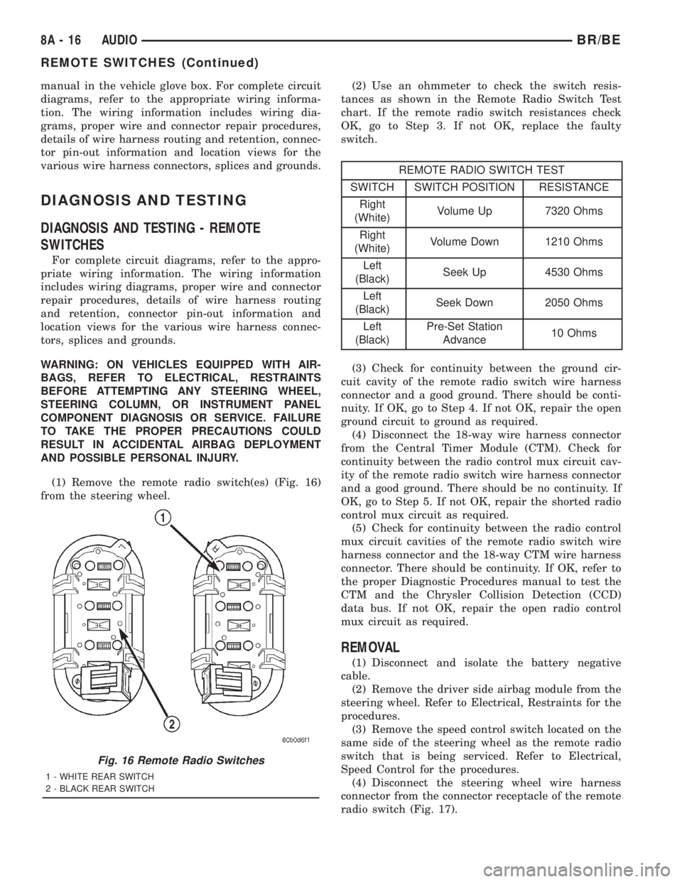
(1) Remove the remote radio switch(es) (Fig. 16)
from the steering wheel.(2) Use an ohmmeter to check the switch resis-
tances as shown in the Remote Radio Switch Test
chart. If the remote radio switch resistances check
OK, go to Step 3. If not OK, replace the faulty
switch.
REMOTE RADIO SWITCH TEST
SWITCH SWITCH POSITION RESISTANCE
Right
(White)Volume Up 7320 Ohms
Right
(White)Volume Down 1210 Ohms
Left
(Black)Seek Up 4530 Ohms
Left
(Black)Seek Down 2050 Ohms
Left
(Black)Pre-Set Station
Advance10 Ohms
(3) Check for continuity between the ground cir-
cuit cavity of the remote radio switch wire harness
connector and a good ground. There should be conti-
nuity. If OK, go to Step 4. If not OK, repair the open
ground circuit to ground as required.
(4) Disconnect the 18-way wire harness connector
from the Central Timer Module (CTM). Check for
continuity between the radio control mux circuit cav-
ity of the remote radio switch wire harness connector
and a good ground. There should be no continuity. If
OK, go to Step 5. If not OK, repair the shorted radio
control mux circuit as required.
(5) Check for continuity between the radio control
mux circuit cavities of the remote radio switch wire
harness connector and the 18-way CTM wire harness
connector. There should be continuity. If OK, refer to
the proper Diagnostic Procedures manual to test the
CTM and the Chrysler Collision Detection (CCD)
data bus. If not OK, repair the open radio control
mux circuit as required.
REMOVAL
(1) Disconnect and isolate the battery negative
cable.
(2) Remove the driver side airbag module from the
steering wheel. Refer to Electrical, Restraints for the
procedures.
(3) Remove the speed control switch located on the
same side of the steering wheel as the remote radio
switch that is being serviced. Refer to Electrical,
Speed Control for the procedures.
(4) Disconnect the steering wheel wire harness
connector from the connector receptacle of the remote
radio switch (Fig. 17).
Fig. 16 Remote Radio Switches
1 - WHITE REAR SWITCH
2 - BLACK REAR SWITCH
8A - 16 AUDIOBR/BE
REMOTE SWITCHES (Continued)
Page 440 of 2889
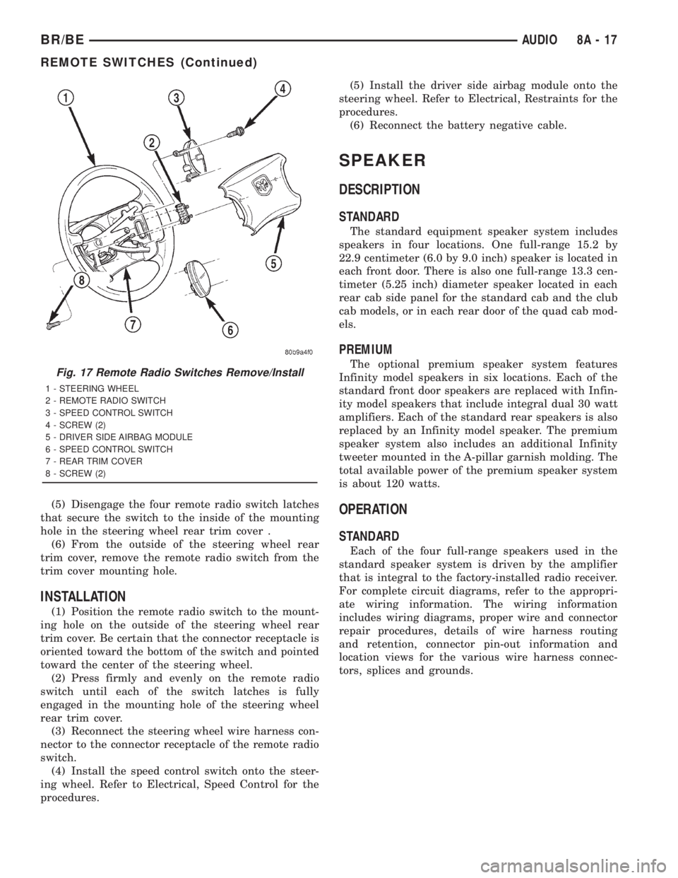
(5) Disengage the four remote radio switch latches
that secure the switch to the inside of the mounting
hole in the steering wheel rear trim cover .
(6) From the outside of the steering wheel rear
trim cover, remove the remote radio switch from the
trim cover mounting hole.
INSTALLATION
(1) Position the remote radio switch to the mount-
ing hole on the outside of the steering wheel rear
trim cover. Be certain that the connector receptacle is
oriented toward the bottom of the switch and pointed
toward the center of the steering wheel.
(2) Press firmly and evenly on the remote radio
switch until each of the switch latches is fully
engaged in the mounting hole of the steering wheel
rear trim cover.
(3) Reconnect the steering wheel wire harness con-
nector to the connector receptacle of the remote radio
switch.
(4) Install the speed control switch onto the steer-
ing wheel. Refer to Electrical, Speed Control for the
procedures.(5) Install the driver side airbag module onto the
steering wheel. Refer to Electrical, Restraints for the
procedures.
(6) Reconnect the battery negative cable.
SPEAKER
DESCRIPTION
STANDARD
The standard equipment speaker system includes
speakers in four locations. One full-range 15.2 by
22.9 centimeter (6.0 by 9.0 inch) speaker is located in
each front door. There is also one full-range 13.3 cen-
timeter (5.25 inch) diameter speaker located in each
rear cab side panel for the standard cab and the club
cab models, or in each rear door of the quad cab mod-
els.
PREMIUM
The optional premium speaker system features
Infinity model speakers in six locations. Each of the
standard front door speakers are replaced with Infin-
ity model speakers that include integral dual 30 watt
amplifiers. Each of the standard rear speakers is also
replaced by an Infinity model speaker. The premium
speaker system also includes an additional Infinity
tweeter mounted in the A-pillar garnish molding. The
total available power of the premium speaker system
is about 120 watts.
OPERATION
STANDARD
Each of the four full-range speakers used in the
standard speaker system is driven by the amplifier
that is integral to the factory-installed radio receiver.
For complete circuit diagrams, refer to the appropri-
ate wiring information. The wiring information
includes wiring diagrams, proper wire and connector
repair procedures, details of wire harness routing
and retention, connector pin-out information and
location views for the various wire harness connec-
tors, splices and grounds.
Fig. 17 Remote Radio Switches Remove/Install
1 - STEERING WHEEL
2 - REMOTE RADIO SWITCH
3 - SPEED CONTROL SWITCH
4 - SCREW (2)
5 - DRIVER SIDE AIRBAG MODULE
6 - SPEED CONTROL SWITCH
7 - REAR TRIM COVER
8 - SCREW (2)
BR/BEAUDIO 8A - 17
REMOTE SWITCHES (Continued)
Page 441 of 2889
PREMIUM
The Infinity speakers used in the premium speaker
system are driven by dual amplifiers that are inte-
gral to each of the front door speakers. One of these
dual amplifiers drives the front door speaker and the
A-pillar mounted tweeter for that side of the vehicle,
while the other amplifier drives the rear speaker for
that side of the vehicle. For complete circuit dia-
grams, to refer to the appropriate wiring information.
The wiring information includes wiring diagrams,
proper wire and connector repair procedures, details
of wire harness routing and retention, connector pin-
out information and location views for the various
wire harness connectors, splices and grounds.
DIAGNOSIS AND TESTING - SPEAKER
For complete circuit diagrams, refer to the appro-
priate wiring information. The wiring information
includes wiring diagrams, proper wire and connector
repair procedures, details of wire harness routing
and retention, connector pin-out information and
location views for the various wire harness connec-
tors, splices and grounds.
WARNING: ON VEHICLES EQUIPPED WITH AIR-
BAGS, REFER TO ELECTRICAL, RESTRAINTS
BEFORE ATTEMPTING ANY STEERING WHEEL,
STEERING COLUMN, OR INSTRUMENT PANEL
COMPONENT DIAGNOSIS OR SERVICE. FAILURE
TO TAKE THE PROPER PRECAUTIONS COULD
RESULT IN ACCIDENTAL AIRBAG DEPLOYMENT
AND POSSIBLE PERSONAL INJURY.
CAUTION: The speaker output of the radio receiver
is a ªfloating groundº system. Do not allow any
speaker lead to short to ground, as damage to the
radio receiver may result.
(1) Turn the ignition switch to the On position.
Turn the radio receiver on. Adjust the balance and
fader controls to check the performance of each indi-
vidual speaker. Note the speaker locations that are
not performing correctly. If only an Infinity A-pillar
or an Infinity rear speaker is inoperative, go to Step
8. If any other speaker is inoperative, go to Step 2.
NOTE: If the vehicle is equipped with the Infinity
premium speaker package and all of the speakers
are inoperative, refer to Filter, Choke, and Speaker
Relay in the Diagnosis and Testing section of this
group.
(2) Turn the radio receiver off. Turn the ignition
switch to the Off position. Disconnect and isolate the
battery negative cable. Remove the radio receiver
from the instrument panel. Check both the feed (+)circuit and return (±) circuit cavities for the inopera-
tive speaker location(s) in the radio receiver wire
harness connectors for continuity to ground. In each
case, there should be no continuity. If OK, go to Step
3. If not OK, repair the shorted speaker feed (+)
and/or return (±) circuit(s) to the speaker as required.
(3) If the inoperative speaker is an Infinity-ampli-
fied speaker, go to Step 5. If the vehicle is equipped
with the standard speaker system, check the resis-
tance between the speaker feed (+) circuit and return
(±) circuit cavities of the radio receiver wire harness
connectors for the inoperative speaker location(s).
The meter should read between 2.5 and 4 ohms
(speaker resistance). If OK, go to Step 4. If not OK,
go to Step 5.
(4) Install a known good radio receiver. Connect
the battery negative cable. Turn the ignition switch
to the On position. Turn on the radio receiver and
test the speaker operation. If OK, replace the faulty
radio receiver. If not OK, turn the radio receiver off,
turn the ignition switch to the Off position, discon-
nect and isolate the battery negative cable, remove
the test radio receiver, and go to Step 5.
(5) Disconnect the wire harness connector at the
inoperative standard speaker system speaker or at
the Infinity-amplified front door-mounted speaker.
Check for continuity between the speaker feed (+) cir-
cuit cavities of the radio receiver wire harness con-
nector and the speaker wire harness connector for
the inoperative speaker location. Repeat the check
between the speaker return (±) circuit cavities of the
radio receiver wire harness connector and the
speaker wire harness connector for the inoperative
speaker location. In each case, there should be conti-
nuity. If OK with an Infinity-amplified front door-
mounted speaker, go to Step 6. If OK with the
standard speaker system, replace the faulty speaker.
If not OK, repair the open speaker feed (+) and/or
return (±) circuit(s) as required.
(6) Check for continuity between the ground cir-
cuit cavity in the body half of the wire harness con-
nector for the Infinity-amplified front door-mounted
speaker on the same side of the vehicle as the inop-
erative speaker and a good ground. There should be
continuity. If OK, go to Step 7. If not OK, repair the
open ground circuit to ground as required.
(7) Install the radio receiver. Connect the battery
negative cable. Turn the ignition switch to the On
position. Turn the radio receiver on. Check for bat-
tery voltage at the radio choke output circuit cavity
of the wire harness connector for the Infinity-ampli-
fied front door-mounted speaker on the same side of
the vehicle as the inoperative speaker. If OK, go to
Step 8. If not OK, repair the open radio choke output
circuit to the filter, choke, and speaker relay as
required.
8A - 18 AUDIOBR/BE
SPEAKER (Continued)
Page 442 of 2889
(8) Turn the radio receiver off. Turn the ignition
switch to the Off position. Disconnect and isolate the
battery negative cable. Disconnect the wire harness
connector for the Infinity-amplified front door-
mounted speaker on the same side of the vehicle as
the inoperative speaker. Check both the amplified
feed (+) circuit and amplified return (±) circuit cavi-
ties for the inoperative speaker location in the body
half of the front door speaker wire harness connector
for continuity to ground. In each case, there should
be no continuity. If OK, go to Step 9. If not OK,
repair the shorted amplified feed (+) and/or amplified
return (±) circuit(s) as required.
(9) Disconnect the wire harness connector at the
inoperative speaker. Check for continuity between
the amplified feed (+) circuit cavities in the body half
of the wire harness connector for the Infinity-ampli-
fied front door-mounted speaker on the same side of
the vehicle as the inoperative speaker and the inop-
erative speaker wire harness connector. Repeat the
check between the amplified return (±) circuit cavi-
ties in the body half of the wire harness connector for
the Infinity-amplified front door-mounted speaker on
the same side of the vehicle as the inoperative
speaker and the inoperative speaker wire harness
connector. In each case, there should be continuity. If
OK, go to Step 10. If not OK, repair the open ampli-
fied feed (+) and/or amplified return (±) circuit(s) as
required.
(10) Check the resistance between the amplified
feed (+) circuit and amplified return (±) circuit cavi-
ties for the inoperative speaker in the body half of
the wire harness connector for the Infinity-amplified
front door-mounted speaker on the same side of the
vehicle as the inoperative speaker. The meter should
read between 2.5 and 4 ohms (speaker resistance). If
OK, replace the faulty front door-mounted Infinity
speaker and amplifier unit. If not OK, replace the
faulty A-pillar or rear-mounted Infinity speaker.
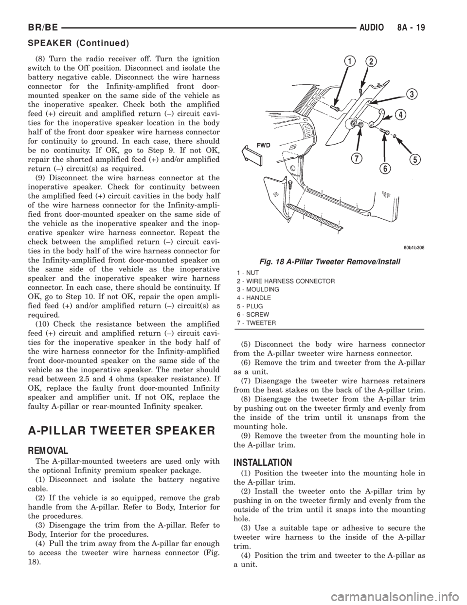
A-PILLAR TWEETER SPEAKER
REMOVAL
The A-pillar-mounted tweeters are used only with
the optional Infinity premium speaker package.
(1) Disconnect and isolate the battery negative
cable.
(2) If the vehicle is so equipped, remove the grab
handle from the A-pillar. Refer to Body, Interior for
the procedures.
(3) Disengage the trim from the A-pillar. Refer to
Body, Interior for the procedures.
(4) Pull the trim away from the A-pillar far enough
to access the tweeter wire harness connector (Fig.
18).(5) Disconnect the body wire harness connector
from the A-pillar tweeter wire harness connector.
(6) Remove the trim and tweeter from the A-pillar
as a unit.
(7) Disengage the tweeter wire harness retainers
from the heat stakes on the back of the A-pillar trim.
(8) Disengage the tweeter from the A-pillar trim
by pushing out on the tweeter firmly and evenly from
the inside of the trim until it unsnaps from the
mounting hole.
(9) Remove the tweeter from the mounting hole in
the A-pillar trim.INSTALLATION
(1) Position the tweeter into the mounting hole in
the A-pillar trim.
(2) Install the tweeter onto the A-pillar trim by
pushing in on the tweeter firmly and evenly from the
outside of the trim until it snaps into the mounting
hole.
(3) Use a suitable tape or adhesive to secure the
tweeter wire harness to the inside of the A-pillar
trim.
(4) Position the trim and tweeter to the A-pillar as
a unit.
Fig. 18 A-Pillar Tweeter Remove/Install
1 - NUT
2 - WIRE HARNESS CONNECTOR
3 - MOULDING
4 - HANDLE
5 - PLUG
6 - SCREW
7 - TWEETER
BR/BEAUDIO 8A - 19
SPEAKER (Continued)
Page 446 of 2889
CHIME/BUZZER
TABLE OF CONTENTS
page page
CHIME WARNING SYSTEM
DESCRIPTION............................1
OPERATION.............................1DIAGNOSIS AND TESTING..................2
CHIME WARNING SYSTEM................2
CHIME WARNING SYSTEM
DESCRIPTION
A chime warning system is standard factory-in-
stalled equipment on this model. The chime warning
system uses a single chime tone generator that is
integral to the Central Timer Module (CTM) to pro-
vide an audible indication of various vehicle condi-
tions that may require the attention of the vehicle
operator. The chime warning system includes the fol-
lowing major components, which are described in fur-
ther detail elsewhere in this service manual:
²Central Timer Module- The Central Timer
Module (CTM) is located under the driver side end of
the instrument panel, inboard of the instrument
panel steering column opening. The CTM contains an
integral chime tone generator to provide all of the
proper chime warning system features based upon
the monitored inputs.
²Door Ajar Switch- A door ajar switch is inte-
gral to the driver side front door latch. This switch
provides an input to the chime warning system indi-
cating whether the driver side front door is open or
closed.
²Headlamp Switch- The headlamp switch is
located on the instrument panel outboard of the
steering column. The headlamp switch provides an
input to the chime warning system indicating when
the exterior lamps are turned On or Off.
²Ignition Switch- A key-in ignition switch is
integral to the ignition switch. The key-in ignition
switch provides an input to the chime warning sys-
tem indicating whether a key is present in the igni-
tion lock cylinder.
²Seat Belt Switch- A seat belt switch is inte-
gral to the driver side front seat belt retractor unit.
The seat belt switch provides an input to the chime
warning system indicating whether the driver side
front seat belt is fastened.
Hard wired circuitry connects many of the chime
warning system components to each other through
the electrical system of the vehicle. These hard wired
circuits are integral to several wire harnesses, which
are routed throughout the vehicle and retained bymany different methods. These circuits may be con-
nected to each other, to the vehicle electrical system
and to the chime warning system components
through the use of a combination of soldered splices,
splice block connectors, and many different types of
wire harness terminal connectors and insulators.
Refer to the appropriate wiring information. The wir-
ing information includes wiring diagrams, proper
wire and connector repair procedures, further details
on wire harness routing and retention, as well as
pin-out and location views for the various wire har-
ness connectors, splices and grounds.
The CTM chime warning system circuitry and the
integral chime tone generator cannot be adjusted or
repaired. If the CTM or the chime tone generator are
damaged or faulty, the CTM unit must be replaced.
OPERATION
The chime warning system is designed to provide an
audible output as an indication of various conditions
that may require the attention or awareness of the
vehicle operator. The chime warning system compo-
nents operate on battery current received through a
fused B(+) fuse in the Junction Block (JB) on a non-
switched fused B(+) circuit so that the system may
operate regardless of the ignition switch position.
The chime warning system provides an audible
indication to the vehicle operator under the following
conditions:
²Fasten Seat Belt Warning- The Central
Timer Module (CTM) chime tone generator will gen-
erate repetitive chime tones at a slow rate to
announce that a hard wired input from the seat belt
switch to the Electro-Mechanical Instrument Cluster
(EMIC) indicates that the driver side front seat belt
is not fastened with the ignition switch in the On
position. Unless the driver side front seat belt is fas-
tened, the chimes will continue to sound for a dura-
tion of about seven seconds each time the ignition
switch is turned to the On position or until the driver
side front seat belt is fastened, whichever occurs
first. This chime tone is based upon a hard wired
chime request input to the CTM from the EMIC, but
is not related to the operation of the EMIC ªSeatbeltº
indicator.
BR/BECHIME/BUZZER 8B - 1
Page 455 of 2889
²Horn relay control - high-line/premium version
only
²VTSS indicator driver - high-line/premium ver-
sion only
²Wiper motor relay control
MESSAGING
The high-line/premium CTM uses the following
messages received from other electronic modules over
the CCD data bus:
²Airbag Deploy (ACM)
²Charging System Failure (PCM)
²Engine RPM (PCM)
²System Voltage (PCM)
²Vehicle Speed (PCM)
²Voltage Fault (PCM)
The high-line/premium CTM provides the following
messages to other electronic modules over the CCD
data bus:
²Engine Enable (PCM)
²Radio Seek Up (Radio)
²Radio Seek Down (Radio)
²Radio Volume Up (Radio)
²Radio Volume Down (Radio)
²Preset Scan (Radio)
DIAGNOSIS AND TESTING - CENTRAL TIMER
MODULE
The hard wired inputs to and outputs from the
Central Timer Module (CTM) may be diagnosed and
tested using conventional diagnostic tools and meth-
ods. Refer to the appropriate wiring information. The
wiring information includes wiring diagrams, proper
wire and connector repair procedures, further details
on wire harness routing and retention, as well as
pin-out and location views for the various wire har-
ness connectors, splices and grounds.
However, conventional diagnostic methods may not
prove conclusive in the diagnosis of the high-line/pre-
mium CTM. In order to obtain conclusive testing of
the high-line/premium CTM, the Chrysler Collision
Detection (CCD) data bus network and all of the elec-
tronic modules that provide inputs to or receive out-
puts from the CTM must also be checked. The most
reliable, efficient, and accurate means to diagnose
the high-line/premium CTM, the CCD data bus net-
work, and the electronic modules that provide inputs
to or receive outputs from the high-line/premium
CTM requires the use of a DRBIIItscan tool and the
appropriate diagnostic information. The DRBIIIt
scan tool can provide confirmation that the CCD data
bus network is functional, that all of the electronic
modules are sending and receiving the proper mes-
sages over the CCD data bus, and that the CTM is
receiving the proper hard wired inputs and respond-ing with the proper hard wired outputs needed to
perform its many functions.
WARNING: ON VEHICLES EQUIPPED WITH AIR-
BAGS, DISABLE THE AIRBAG SYSTEM BEFORE
ATTEMPTING ANY STEERING WHEEL, STEERING
COLUMN, OR INSTRUMENT PANEL COMPONENT
DIAGNOSIS OR SERVICE. DISCONNECT AND ISO-
LATE THE BATTERY NEGATIVE (GROUND) CABLE,
THEN WAIT TWO MINUTES FOR THE AIRBAG SYS-
TEM CAPACITOR TO DISCHARGE BEFORE PER-
FORMING FURTHER DIAGNOSIS OR SERVICE. THIS
IS THE ONLY SURE WAY TO DISABLE THE AIRBAG
SYSTEM. FAILURE TO TAKE THE PROPER PRE-
CAUTIONS COULD RESULT IN ACCIDENTAL AIR-
BAG DEPLOYMENT AND POSSIBLE PERSONAL
INJURY.
NOTE: The following tests may not prove conclu-
sive in the diagnosis of the high-line or premium
versions of the Central Timer Module (CTM). The
most reliable, efficient, and accurate means to diag-
nose the high-line or premium CTM requires the
use of a DRBIIITscan tool and the appropriate diag-
nostic information.
(1) Check the fused B(+) fuse (Fuse 13 - 10
ampere) in the Junction Block (JB). If OK, go to Step
2. If not OK, repair the shorted circuit or component
as required and replace the faulty fuse.
(2) Check for battery voltage at the fused B(+) fuse
(Fuse 13 - 10 ampere) in the JB. If OK, go to Step 3.
If not OK, repair the open fused B(+) circuit between
the JB and the Power Distribution Center (PDC) as
required.
(3) For a base version CTM, check the fused igni-
tion switch output (st-run) fuse (Fuse 11 - 10 ampere)
in the JB. For a high-line/premium version CTM,
check the fused ignition switch output (run-acc) fuse
(Fuse6-25ampere) in the JB. If OK, go to Step 4. If
not OK, repair the shorted circuit or component as
required and replace the faulty fuse.
(4) Turn the ignition switch to the On position. For
a base version CTM, check for battery voltage at the
fused ignition switch output (st-run) fuse (Fuse 11 -
10 ampere) in the JB. For a high-line/premium ver-
sion CTM, check for battery voltage at the fused igni-
tion switch output (run-acc) fuse (Fuse6-25
ampere) in the JB. If OK, go to Step 5. If not OK,
repair the shorted circuit or component as required
and replace the faulty fuse.
(5) Turn the ignition switch to the Off position.
Disconnect and isolate the battery negative cable.
Remove the CTM from its mounting bracket to access
the CTM wire harness connector(s). Disconnect the
instrument panel wire harness connector(s) for the
8E - 4 ELECTRONIC CONTROL MODULESBR/BE
BODY CONTROL/CENTRAL TIMER MODULE (Continued)
Page 463 of 2889
²ABS Warning Lamp
²Brake Warning Lamp
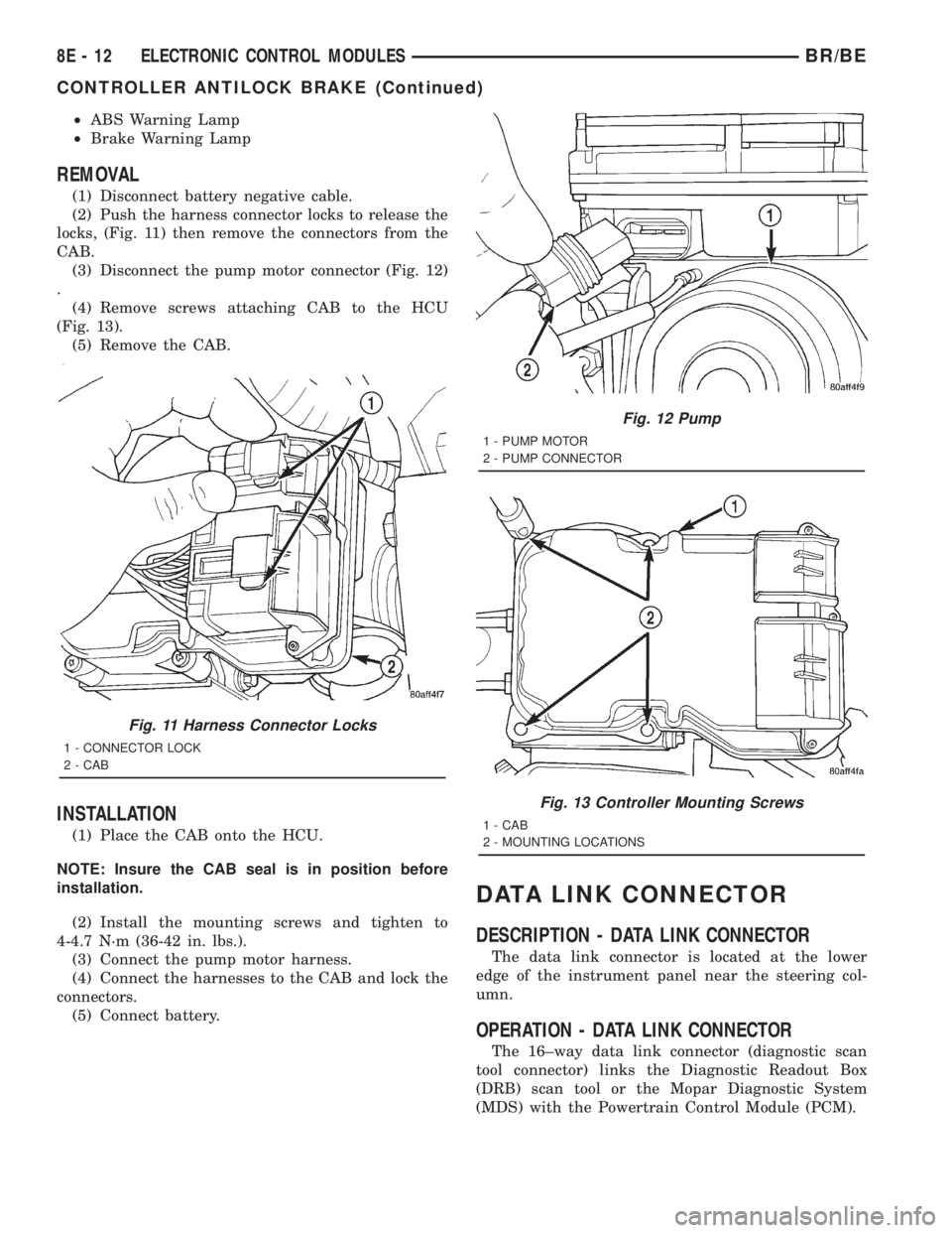
REMOVAL
(1) Disconnect battery negative cable.
(2) Push the harness connector locks to release the
locks, (Fig. 11) then remove the connectors from the
CAB.
(3) Disconnect the pump motor connector (Fig. 12)
.
(4) Remove screws attaching CAB to the HCU
(Fig. 13).
(5) Remove the CAB.
INSTALLATION
(1) Place the CAB onto the HCU.
NOTE: Insure the CAB seal is in position before
installation.
(2) Install the mounting screws and tighten to
4-4.7 N´m (36-42 in. lbs.).
(3) Connect the pump motor harness.
(4) Connect the harnesses to the CAB and lock the
connectors.
(5) Connect battery.
DATA LINK CONNECTOR
DESCRIPTION - DATA LINK CONNECTOR
The data link connector is located at the lower
edge of the instrument panel near the steering col-
umn.
OPERATION - DATA LINK CONNECTOR
The 16±way data link connector (diagnostic scan
tool connector) links the Diagnostic Readout Box
(DRB) scan tool or the Mopar Diagnostic System
(MDS) with the Powertrain Control Module (PCM).
Fig. 11 Harness Connector Locks
1 - CONNECTOR LOCK
2 - CAB
Fig. 12 Pump
1 - PUMP MOTOR
2 - PUMP CONNECTOR
Fig. 13 Controller Mounting Screws
1 - CAB
2 - MOUNTING LOCATIONS
8E - 12 ELECTRONIC CONTROL MODULESBR/BE
CONTROLLER ANTILOCK BRAKE (Continued)