2001 DODGE RAM check oil
[x] Cancel search: check oilPage 90 of 2889
(8) Disconnect the stabilizer bar links at the axle
brackets.
(9) Disconnect the shock absorbers from axle
brackets.
(10) Disconnect the track bar from the axle
bracket.
(11) Disconnect the tie rod and drag link from the
steering knuckles.
(12) Position the axle with a suitable lifting device
under the axle assembly.
(13) Secure axle to lifting device.
(14) Mark suspension alignment cams for installa-
tion reference.
(15) Disconnect the upper and lower suspension
arms from the axle bracket.
(16) Lower the axle. The coil springs will drop
with the axle.
(17) Remove the coil springs from the axle bracket.
INSTALLATION
CAUTION: Suspension components with rubber
bushings should be tightened with the weight of the
vehicle on the suspension, at normal height. If
springs are not at their normal ride position, vehicle
ride comfort could be affected and premature bush-
ing wear may occur. Rubber bushings must never
be lubricated.
(1) Support the axle on a suitable lifting device.
(2) Secure axle to lifting device.
(3) Position the axle under the vehicle.
(4) Install the springs, retainer clip and bolts.
(5) Raise the axle and align it with the spring
pads.
(6) Position the upper and lower suspension arms
in the axle brackets. Install bolts, nuts and align the
suspension alignment cams to the reference marks.
Do not tighten at this time.
(7) Connect the track bar to the axle bracket and
install the bolt. Do not tighten at this time.
(8) Install the shock absorber and tighten bolts to
121 N´m (89 ft. lbs.) torque.
(9) Install the stabilizer bar link to the axle
bracket. Tighten the nut to 37 N´m (27 ft. lbs.)
torque.
(10) Install the drag link and tie rod to the steer-
ing knuckles and tighten the nuts to 88 N´m (65 ft.
lbs.) torque.
(11) Install the ABS wheel speed sensors, if
equipped. Refer to group 5, Brakes, for proper proce-
dures.
(12) Install the brake calipers and rotors. Refer to
Group 5, Brakes, for proper procedures.
(13) Connect the vent hose to the tube fitting.
(14) Connect vacuum hose and electrical connector
to disconnect housing.(15) Install front propeller shaft.
(16) Check and add differential lubricant, if neces-
sary. Refer to Lubricant Specifications in this section
for lubricant requirements.
(17) Install the wheel and tire assemblies.
(18) Remove the supports and lower the vehicle.
(19) Tighten the upper suspension arm nuts at
axle to 121 N´m (89 ft. lbs.) torque. Tighten the
upper suspension arm nuts at frame to 84 N´m (62 ft.
lbs.) torque.
(20) Tighten the lower suspension arm nuts at
axle to 84 N´m (62 ft. lbs.) torque. Tighten the lower
suspension arm nuts at frame to 119 N´m (88 ft. lbs.)
torque.
(21) Tighten the track bar bolt at the axle bracket
to 176 N´m (130 ft. lbs.) torque.
(22) Check the front wheel alignment.
ADJUSTMENTS
Ring and pinion gears are supplied as matched
sets only. The identifying numbers for the ring and
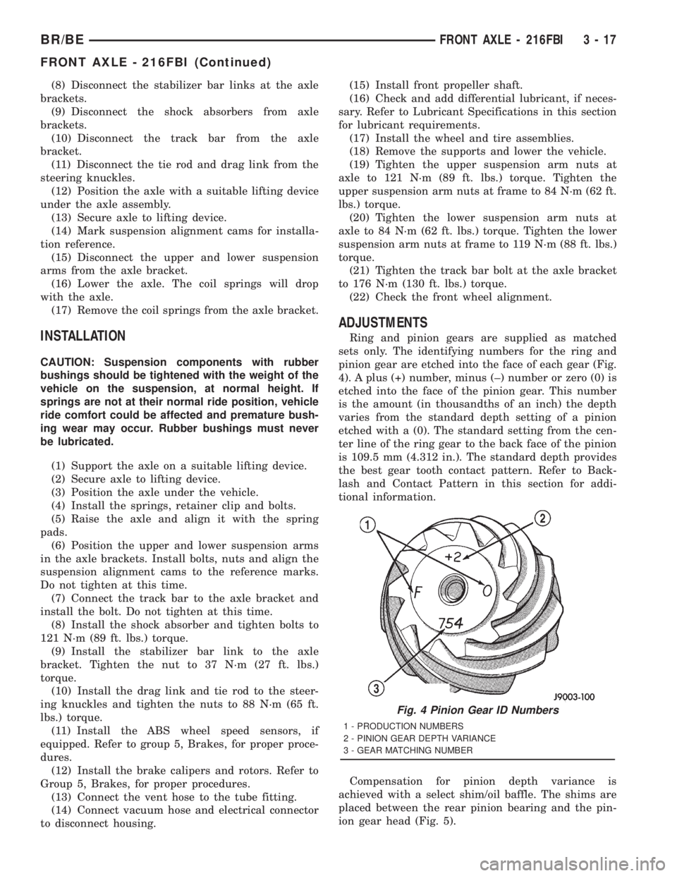
pinion gear are etched into the face of each gear (Fig.
4). A plus (+) number, minus (±) number or zero (0) is
etched into the face of the pinion gear. This number
is the amount (in thousandths of an inch) the depth
varies from the standard depth setting of a pinion
etched with a (0). The standard setting from the cen-
ter line of the ring gear to the back face of the pinion
is 109.5 mm (4.312 in.). The standard depth provides
the best gear tooth contact pattern. Refer to Back-
lash and Contact Pattern in this section for addi-
tional information.
Compensation for pinion depth variance is
achieved with a select shim/oil baffle. The shims are
placed between the rear pinion bearing and the pin-
ion gear head (Fig. 5).
Fig. 4 Pinion Gear ID Numbers
1 - PRODUCTION NUMBERS
2 - PINION GEAR DEPTH VARIANCE
3 - GEAR MATCHING NUMBER
BR/BEFRONT AXLE - 216FBI 3 - 17
FRONT AXLE - 216FBI (Continued)
Page 123 of 2889

REMOVAL
(1) Raise and support the vehicle.
(2) Remove the wheels and tires.
(3) Remove the brake calipers and rotors. Refer to
Group 5, Brakes, for proper procedures.
(4) Remove ABS wheel speed sensors, if equipped.
Refer to Group 5, Brakes, for proper procedures.
(5) Disconnect the axle vent hose.
(6) Disconnect vacuum hose and electrical connec-
tor at disconnect housing.
(7) Remove the front propeller shaft.
(8) Disconnect the stabilizer bar links at the axle
brackets.
(9) Disconnect the shock absorbers from axle
brackets.
(10) Disconnect the track bar from the axle
bracket.
(11) Disconnect the tie rod and drag link from the
steering knuckles.
(12) Position the axle with a suitable lifting device
under the axle assembly.
(13) Secure axle to lifting device.
(14) Mark suspension alignment cams for installa-
tion reference.
(15) Disconnect the upper and lower suspension
arms from the axle bracket.
(16) Lower the axle. The coil springs will drop
with the axle.
(17) Remove the coil springs from the axle bracket.
INSTALLATION
CAUTION: Suspension components with rubber
bushings should be tightened with the weight of the
vehicle on the suspension, at normal height. If
springs are not at their normal ride position, vehicle
ride comfort could be affected and premature bush-
ing wear may occur. Rubber bushings must never
be lubricated.
(1) Support the axle on a suitable lifting device.
(2) Secure axle to lifting device.
(3) Position the axle under the vehicle.
(4) Install the springs, retainer clip and bolts.
(5) Raise the axle and align it with the spring
pads.
(6) Position the upper and lower suspension arms
in the axle brackets. Install bolts, nuts and align the
suspension alignment cams to the reference marks.
Do not tighten at this time.
(7) Connect the track bar to the axle bracket and
install the bolt. Do not tighten at this time.
(8) Install the shock absorber and tighten bolts to
121 N´m (89 ft. lbs.) torque.(9) Install the stabilizer bar link to the axle
bracket. Tighten the nut to 37 N´m (27 ft. lbs.)
torque.
(10) Install the drag link and tie rod to the steer-
ing knuckles and tighten the nuts to 88 N´m (65 ft.
lbs.) torque.
(11) Install the ABS wheel speed sensors, if
equipped. Refer to group 5, Brakes, for proper proce-
dures.
(12) Install the brake calipers and rotors. Refer to
Group 5, Brakes, for proper procedures.
(13) Connect the vent hose to the tube fitting.
(14) Connect vacuum hose and electrical connector
to disconnect housing.
(15) Install front propeller shaft.
(16) Check and add differential lubricant, if neces-
sary. Refer to Lubricant Specifications in this section
for lubricant requirements.
(17) Install the wheel and tire assemblies.
(18) Remove the supports and lower the vehicle.
(19) Tighten the upper suspension arm nuts at
axle to 121 N´m (89 ft. lbs.) torque. Tighten the
upper suspension arm nuts at frame to 84 N´m (62 ft.
lbs.) torque.
(20) Tighten the lower suspension arm nuts at
axle to 84 N´m (62 ft. lbs.) torque. Tighten the lower
suspension arm nuts at frame to 119 N´m (88 ft. lbs.)
torque.
(21) Tighten the track bar bolt at the axle bracket
to 176 N´m (130 ft. lbs.) torque.
(22) Check the front wheel alignment.ADJUSTMENTS
Ring and pinion gears are supplied as matched
sets only. The identifying numbers for the ring and
pinion gear are etched into the face of each gear (Fig.
4). A plus (+) number, minus (±) number or zero (0) is
etched into the face of the pinion gear. This number
is the amount (in thousandths of an inch) the depth
varies from the standard depth setting of a pinion
etched with a (0). The standard setting from the cen-
ter line of the ring gear to the back face of the pinion
is 127 mm (5.00 in.). The standard depth provides
the best gear tooth contact pattern. Refer to Back-
lash and Contact Pattern in this section for addi-
tional information.
Compensation for pinion depth variance is
achieved with a select shim/oil baffle. The shims are
placed between the rear pinion bearing and the pin-
ion gear head (Fig. 5).
If a new gear set is being installed, note the depth
variance etched into both the original and replace-
ment pinion. Add or subtract this number from the
thickness of the original depth shim/oil slinger to
compensate for the difference in the depth variances.
Refer to the Depth Variance chart.
3 - 50 FRONT AXLE - 248FBIBR/BE
FRONT AXLE - 248FBI (Continued)
Page 169 of 2889

CAUTION: Never loosen pinion nut to decrease pin-
ion bearing rotating torque and never exceed spec-
ified preload torque. If rotating torque is exceeded,
a new collapsible spacer must be installed.(10) If the rotating torque is low, use Holder 6719
to hold the companion flange (Fig. 23) and tighten
the pinion nut in 6.8 N´m (5 ft. lbs.) increments until
proper rotating torque is achieved.
NOTE: The bearing rotating torque should be con-
stant during a complete revolution of the pinion. If
the rotating torque varies, this indicates a binding
condition.
(11) The seal replacement is unacceptable if the
final pinion nut torque is less than 285 N´m (210 ft.
lbs.).
(12) Install the propeller shaft with the installa-
tion reference marks aligned.
(13) Tighten the companion flange bolts to 108
N´m (80 ft. lbs.).
(14) Install the brake drums.
(15) Install wheel and tire assemblies and lower
the vehicle.
(16) Check the differential housing lubricant level.
DIFFERENTIAL
REMOVAL
(1) Raise and support the vehicle.
(2) Remove lubricant fill hole plug from the differ-
ential housing cover.
(3) Remove differential housing cover and drain
the lubricant from the housing.
(4) Clean the housing cavity with a flushing oil,
light engine oil or lint free cloth.Do not use water,
steam, kerosene or gasoline for cleaning.
(5) Remove the axle shafts.
(6) Remove RWAL/ABS sensor from housing.
NOTE: Side play resulting from bearing races being
loose on case hubs requires replacement of the dif-
ferential case.
(7) Mark the differential housing and differential
bearing caps for installation reference (Fig. 25).
(8) Remove bearing threaded adjuster lock from
each bearing cap. Loosen the bolts, but do not
remove the bearing caps.
(9) Loosen the threaded adjusters with Wrench
C-4164 (Fig. 26).
(10) Hold the differential case while removing
bearing caps and adjusters.
(11) Remove the differential case.
NOTE: Each differential bearing cup and threaded
adjuster must be kept with their respective bearing.
Fig. 23 Pinion Nut
1 - DIFFERENTIAL HOUSING
2 - COMPANION FLANGE HOLDER
3 - TORQUE WRENCH
Fig. 24 Pinion Rotation Torque
1 - COMPANION FLANGE
2 - INCH POUND TORQUE WRENCH
3 - 96 REAR AXLE-91/4BR/BE
PINION SEAL (Continued)
Page 200 of 2889
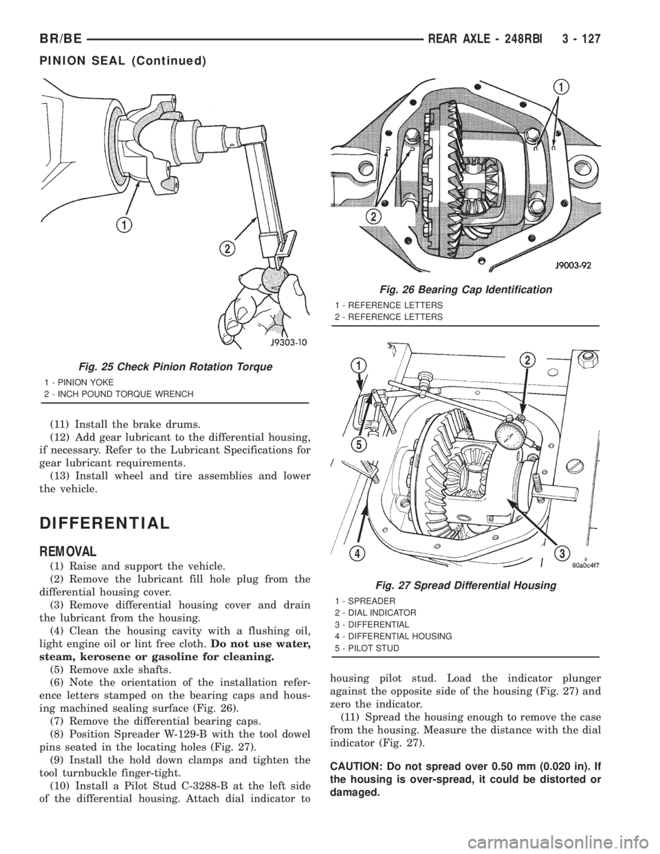
(11) Install the brake drums.
(12) Add gear lubricant to the differential housing,
if necessary. Refer to the Lubricant Specifications for
gear lubricant requirements.
(13) Install wheel and tire assemblies and lower
the vehicle.
DIFFERENTIAL
REMOVAL
(1) Raise and support the vehicle.
(2) Remove the lubricant fill hole plug from the
differential housing cover.
(3) Remove differential housing cover and drain
the lubricant from the housing.
(4) Clean the housing cavity with a flushing oil,
light engine oil or lint free cloth.Do not use water,
steam, kerosene or gasoline for cleaning.
(5) Remove axle shafts.
(6) Note the orientation of the installation refer-
ence letters stamped on the bearing caps and hous-
ing machined sealing surface (Fig. 26).
(7) Remove the differential bearing caps.
(8) Position Spreader W-129-B with the tool dowel
pins seated in the locating holes (Fig. 27).
(9) Install the hold down clamps and tighten the
tool turnbuckle finger-tight.
(10) Install a Pilot Stud C-3288-B at the left side
of the differential housing. Attach dial indicator tohousing pilot stud. Load the indicator plunger
against the opposite side of the housing (Fig. 27) and
zero the indicator.
(11) Spread the housing enough to remove the case
from the housing. Measure the distance with the dial
indicator (Fig. 27).
CAUTION: Do not spread over 0.50 mm (0.020 in). If
the housing is over-spread, it could be distorted or
damaged.
Fig. 25 Check Pinion Rotation Torque
1 - PINION YOKE
2 - INCH POUND TORQUE WRENCH
Fig. 26 Bearing Cap Identification
1 - REFERENCE LETTERS
2 - REFERENCE LETTERS
Fig. 27 Spread Differential Housing
1 - SPREADER
2 - DIAL INDICATOR
3 - DIFFERENTIAL
4 - DIFFERENTIAL HOUSING
5 - PILOT STUD
BR/BEREAR AXLE - 248RBI 3 - 127
PINION SEAL (Continued)
Page 260 of 2889
DIFFERENTIAL
REMOVAL
(1) Raise and support the vehicle.
(2) Remove the lubricant fill hole plug from the
differential housing cover.
(3) Remove differential housing cover and drain
the lubricant from the housing.
(4) Clean the housing cavity with a flushing oil,
light engine oil or lint free cloth.Do not use water,
steam, kerosene or gasoline for cleaning.
(5) Remove axle shafts.
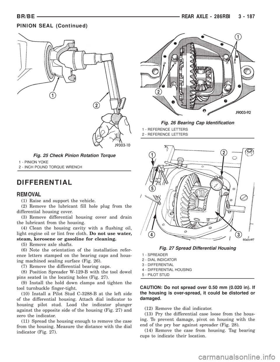
(6) Note the orientation of the installation refer-
ence letters stamped on the bearing caps and hous-
ing machined sealing surface (Fig. 26).
(7) Remove the differential bearing caps.
(8) Position Spreader W-129-B with the tool dowel
pins seated in the locating holes (Fig. 27).
(9) Install the hold down clamps and tighten the
tool turnbuckle finger-tight.
(10) Install a Pilot Stud C-3288-B at the left side
of the differential housing. Attach dial indicator to
housing pilot stud. Load the indicator plunger
against the opposite side of the housing (Fig. 27) and
zero the indicator.
(11) Spread the housing enough to remove the case
from the housing. Measure the distance with the dial
indicator (Fig. 27).CAUTION: Do not spread over 0.50 mm (0.020 in). If
the housing is over-spread, it could be distorted or
damaged.
(12) Remove the dial indicator.
(13) Pry the differential case loose from the hous-
ing. To prevent damage, pivot on housing with the
end of the pry bar against spreader (Fig. 28).
(14) Remove the case from housing. Tag bearing
cups to indicate their location.
Fig. 25 Check Pinion Rotation Torque
1 - PINION YOKE
2 - INCH POUND TORQUE WRENCH
Fig. 26 Bearing Cap Identification
1 - REFERENCE LETTERS
2 - REFERENCE LETTERS
Fig. 27 Spread Differential Housing
1 - SPREADER
2 - DIAL INDICATOR
3 - DIFFERENTIAL
4 - DIFFERENTIAL HOUSING
5 - PILOT STUD
BR/BEREAR AXLE - 286RBI 3 - 187
PINION SEAL (Continued)
Page 269 of 2889
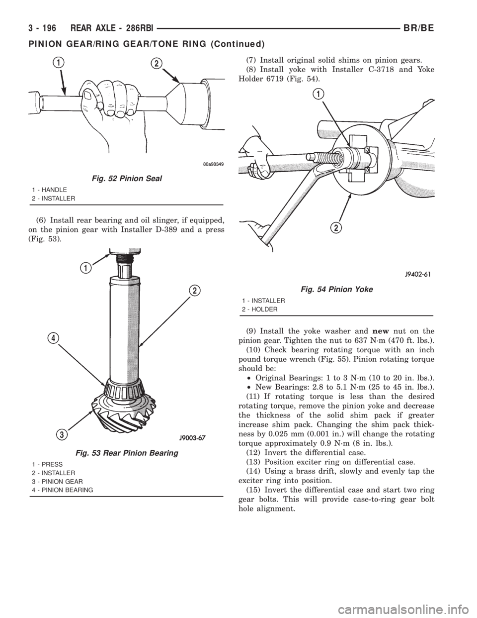
(6) Install rear bearing and oil slinger, if equipped,
on the pinion gear with Installer D-389 and a press
(Fig. 53).(7) Install original solid shims on pinion gears.
(8) Install yoke with Installer C-3718 and Yoke
Holder 6719 (Fig. 54).
(9) Install the yoke washer andnewnut on the
pinion gear. Tighten the nut to 637 N´m (470 ft. lbs.).
(10) Check bearing rotating torque with an inch
pound torque wrench (Fig. 55). Pinion rotating torque
should be:
²Original Bearings: 1 to 3 N´m (10 to 20 in. lbs.).
²New Bearings: 2.8 to 5.1 N´m (25 to 45 in. lbs.).
(11) If rotating torque is less than the desired
rotating torque, remove the pinion yoke and decrease
the thickness of the solid shim pack if greater
increase shim pack. Changing the shim pack thick-
ness by 0.025 mm (0.001 in.) will change the rotating
torque approximately 0.9 N´m (8 in. lbs.).
(12) Invert the differential case.
(13) Position exciter ring on differential case.
(14) Using a brass drift, slowly and evenly tap the
exciter ring into position.
(15) Invert the differential case and start two ring
gear bolts. This will provide case-to-ring gear bolt
hole alignment.
Fig. 52 Pinion Seal
1 - HANDLE
2 - INSTALLER
Fig. 53 Rear Pinion Bearing
1 - PRESS
2 - INSTALLER
3 - PINION GEAR
4 - PINION BEARING
Fig. 54 Pinion Yoke
1 - INSTALLER
2 - HOLDER
3 - 196 REAR AXLE - 286RBIBR/BE
PINION GEAR/RING GEAR/TONE RING (Continued)
Page 276 of 2889
WARNING
WARNING: DUST AND DIRT ACCUMULATING ON
BRAKE PARTS DURING NORMAL USE MAY CON-
TAIN ASBESTOS FIBERS FROM PRODUCTION OR
AFTERMARKET LININGS. BREATHING EXCESSIVE
CONCENTRATIONS OF ASBESTOS FIBERS CAN
CAUSE SERIOUS BODILY HARM. EXERCISE CARE
WHEN SERVICING BRAKE PARTS. DO NOT CLEAN
BRAKE PARTS WITH COMPRESSED AIR OR BY
DRY BRUSHING. USE A VACUUM CLEANER SPE-
CIFICALLY DESIGNED FOR THE REMOVAL OF
ASBESTOS FIBERS FROM BRAKE COMPONENTS.
IF A SUITABLE VACUUM CLEANER IS NOT AVAIL-
ABLE, CLEANING SHOULD BE DONE WITH A
WATER DAMPENED CLOTH. DO NOT SAND, OR
GRIND BRAKE LINING UNLESS EQUIPMENT USED
IS DESIGNED TO CONTAIN THE DUST RESIDUE.
DISPOSE OF ALL RESIDUE CONTAINING ASBES-
TOS FIBERS IN SEALED BAGS OR CONTAINERS
TO MINIMIZE EXPOSURE TO YOURSELF AND OTH-
ERS. FOLLOW PRACTICES PRESCRIBED BY THE
OCCUPATIONAL SAFETY AND HEALTH ADMINIS-
TRATION AND THE ENVIRONMENTAL PROTECTION
AGENCY FOR THE HANDLING, PROCESSING, AND
DISPOSITION OF DUST OR DEBRIS THAT MAY
CONTAIN ASBESTOS FIBERS.
CAUTION: Never use gasoline, kerosene, alcohol,
motor oil, transmission fluid, or any fluid containing
mineral oil to clean the system components. These
fluids damage rubber cups and seals. Use only
fresh brake fluid or Mopar brake cleaner to clean or
flush brake system components. These are the only
cleaning materials recommended. If system contam-
ination is suspected, check the fluid for dirt, discol-
oration, or separation into distinct layers. Also
check the reservoir cap seal for distortion. Drain
and flush the system with new brake fluid if con-
tamination is suspected.
CAUTION: Use Mopar brake fluid, or an equivalent
quality fluid meeting SAE/DOT standards J1703 and
DOT 3. Brake fluid must be clean and free of con-
taminants. Use fresh fluid from sealed containers
only to ensure proper antilock component opera-
tion.
CAUTION: Use Mopar multi-mileage or high temper-
ature grease to lubricate caliper slide surfaces,
drum brake pivot pins, and shoe contact points on
the backing plates. Use multi-mileage grease or GE
661 or Dow 111 silicone grease on caliper slide pins
to ensure proper operation.
DIAGNOSIS AND TESTING - BASE BRAKE
SYSTEM
Base brake components consist of the brake shoes,
calipers, wheel cylinders, brake drums, rotors, brake
lines, master cylinder, booster, and parking brake
components.
Brake diagnosis involves determining if the prob-
lem is related to a mechanical, hydraulic, or vacuum
operated component.
The first diagnosis step is the preliminary check.
PRELIMINARY BRAKE CHECK
(1) Check condition of tires and wheels. Damaged
wheels and worn, damaged, or underinflated tires
can cause pull, shudder, vibration, and a condition
similar to grab.
(2) If complaint was based on noise when braking,
check suspension components. Jounce front and rear
of vehicle and listen for noise that might be caused
by loose, worn or damaged suspension or steering
components.
(3) Inspect brake fluid level and condition. Note
that the brake reservoir fluid level will decrease in
proportion to normal lining wear.Also note that
brake fluid tends to darken over time. This is
normal and should not be mistaken for contam-
ination.
(a) If fluid level is abnormally low, look for evi-
dence of leaks at calipers, wheel cylinders, brake
lines, and master cylinder.
(b) If fluid appears contaminated, drain out a
sample to examine. System will have to be flushed
if fluid is separated into layers, or contains a sub-
stance other than brake fluid. The system seals
and cups will also have to be replaced after flush-
ing. Use clean brake fluid to flush the system.
(4) Check parking brake operation. Verify free
movement and full release of cables and pedal. Also
note if vehicle was being operated with parking
brake partially applied.
(5) Check brake pedal operation. Verify that pedal
does not bind and has adequate free play. If pedal
lacks free play, check pedal and power booster for
being loose or for bind condition. Do not road test
until condition is corrected.
(6) Check booster vacuum check valve and hose.
(7) If components checked appear OK, road test
the vehicle.
ROAD TESTING
(1) If complaint involved low brake pedal, pump
pedal and note if it comes back up to normal height.
(2) Check brake pedal response with transmission
in Neutral and engine running. Pedal should remain
firm under constant foot pressure.
BR/BEBRAKES 5 - 5
HYDRAULIC/MECHANICAL (Continued)
Page 285 of 2889
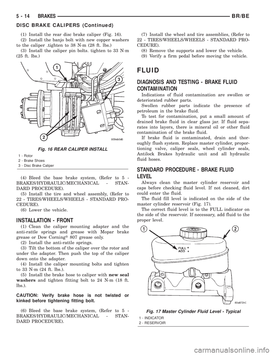
(1) Install the rear disc brake caliper (Fig. 16).
(2) Install the banjo bolt with new copper washers
to the caliper .tighten to 38 N´m (28 ft. lbs.)
(3) Install the caliper pin bolts. tighten to 33 N´m
(25 ft. lbs.)
(4) Bleed the base brake system, (Refer to 5 -
BRAKES/HYDRAULIC/MECHANICAL - STAN-
DARD PROCEDURE).
(5) Install the tire and wheel assembly, (Refer to
22 - TIRES/WHEELS/WHEELS - STANDARD PRO-
CEDURE).
(6) Lower the vehicle.
INSTALLATION - FRONT
(1) Clean the caliper mounting adapter and the
anti-rattle springs and grease with Mopar brake
grease or Dow Corningt807 grease only.
(2) Install the anti-rattle springs.
(3) Tilt the bottom of the caliper over the rotor and
under the adapter. Then push the top of the caliper
down onto the adapter.
(4) Install the caliper mounting bolts and tighten
to 33 N´m (24 ft. lbs.).
(5) Install the brake hose to caliper withnew seal
washersand tighten fitting bolt to 24 N´m (18 ft.
lbs.).
CAUTION: Verify brake hose is not twisted or
kinked before tightening fitting bolt.
(6) Bleed the base brake system, (Refer to 5 -
BRAKES/HYDRAULIC/MECHANICAL - STAN-
DARD PROCEDURE).(7) Install the wheel and tire assemblies, (Refer to
22 - TIRES/WHEELS/WHEELS - STANDARD PRO-
CEDURE).
(8) Remove the supports and lower the vehicle.
(9) Verify a firm pedal before moving the vehicle.
FLUID
DIAGNOSIS AND TESTING - BRAKE FLUID
CONTAMINATION
Indications of fluid contamination are swollen or
deteriorated rubber parts.
Swollen rubber parts indicate the presence of
petroleum in the brake fluid.
To test for contamination, put a small amount of
drained brake fluid in clear glass jar. If fluid sepa-
rates into layers, there is mineral oil or other fluid
contamination of the brake fluid.
If brake fluid is contaminated, drain and thor-
oughly flush system. Replace master cylinder, propor-
tioning valve, caliper seals, wheel cylinder seals,
Antilock Brakes hydraulic unit and all hydraulic
fluid hoses.
STANDARD PROCEDURE - BRAKE FLUID
LEVEL
Always clean the master cylinder reservoir and
caps before checking fluid level. If not cleaned, dirt
could enter the fluid.
The fluid fill level is indicated on the side of the
master cylinder reservoir (Fig. 17).
The correct fluid level is to the FULL indicator on
the side of the reservoir. If necessary, add fluid to the
proper level.
Fig. 16 REAR CALIPER INSTALL
1 - Rotor
2 - Brake Shoes
3 - Disc Brake Caliper
Fig. 17 Master Cylinder Fluid Level - Typical
1 - INDICATOR
2 - RESERVOIR
5 - 14 BRAKESBR/BE
DISC BRAKE CALIPERS (Continued)