2001 DODGE RAM check oil
[x] Cancel search: check oilPage 27 of 2889
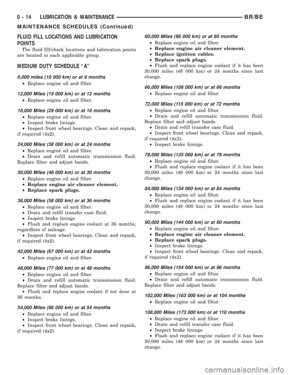
FLUID FILL LOCATIONS AND LUBRICATION
POINTS
The fluid fill/check locations and lubrication points
are located in each applicable group.
MEDIUM DUTY SCHEDULE ªAº
6,000 miles (10 000 km) or at 6 months
²Replace engine oil and filter.
12,000 Miles (19 000 km) or at 12 months
²Replace engine oil and filter.
18,000 Miles (29 000 km) or at 18 months
²Replace engine oil and filter.
²Inspect brake linings.
²Inspect front wheel bearings. Clean and repack,
if required (4x2).
24,000 Miles (38 000 km) or at 24 months
²Replace engine oil and filter.
²Drain and refill automatic transmission fluid.
Replace filter and adjust bands.
30,000 Miles (48 000 km) or at 30 months
²Replace engine oil and filter.
²Replace engine air cleaner element.
²Replace spark plugs.
36,000 Miles (58 000 km) or at 36 months
²Replace engine oil and filter.
²Drain and refill transfer case fluid.
²Inspect brake linings
²Flush and replace engine coolant at 36 months,
regardless of mileage.
²Inspect front wheel bearings. Clean and repack,
if required (4x2).
42,000 Miles (67 000 km) or at 42 months
²Replace engine oil and filter.
48,000 Miles (77 000 km) or at 48 months
²Replace engine oil and filter.
²Drain and refill automatic transmission fluid.
Replace filter and adjust bands.
²Flush and replace engine coolant if not done at
36 months.
54,000 Miles (86 000 km) or at 54 months
²Replace engine oil and filter.
²Inspect brake linings.
²Inspect front wheel bearings. Clean and repack,
if required (4x2).
60,000 Miles (96 000 km) or at 60 months
²Replace engine oil and filter.
²Replace engine air cleaner element.
²Replace ignition cables.
²Replace spark plugs.
²Flush and replace engine coolant if it has been
30,000 miles (48 000 km) or 24 months since last
change.
66,000 Miles (106 000 km) or at 66 months
²Replace engine oil and filter.
72,000 Miles (115 000 km) or at 72 months
²Replace engine oil and filter.
²Drain and refill automatic transmission fluid.
Replace filter and adjust bands.
²Drain and refill transfer case fluid.
²Inspect front wheel bearings. Clean and repack,
if required (4x2).
²Inspect brake linings.
78,000 Miles (125 000 km) or at 78 months
²Replace engine oil and filter.
²Flush and replace engine coolant if it has been
30,000 miles (48 000 km) or 24 months since last
change.
84,000 Miles (134 000 km) or at 84 months
²Replace engine oil and filter.
²Flush and replace engine coolant if it has been
30,000 miles (48 000 km) or 24 months since last
change.
90,000 Miles (144 000 km) or at 90 months
²Replace engine oil and filter.
²Replace engine air cleaner element.
²Replace spark plugs.
²Inspect brake linings.
²Inspect front wheel bearings. Clean and repack,
if required (4x2).
96,000 Miles (154 000 km) or at 96 months
²Replace engine oil and filter.
²Drain and refill automatic transmission fluid.
Replace filter and adjust bands.
102,000 Miles (163 000 km) or at 104 months
²Replace engine oil and filter.
108,000 Miles (173 000 km) or at 110 months
²Replace engine oil and filter.
²Drain and refill transfer case fluid.
²Inspect brake linings.
²Flush and replace engine coolant if it has been
30,000 miles (48 000 km) or 24 months since last
change.
0 - 14 LUBRICATION & MAINTENANCEBR/BE
MAINTENANCE SCHEDULES (Continued)
Page 30 of 2889
²Inspect brake linings.
³Off-the-highway operation, trailer towing snow
plowing, prolonged operation with heavy loading,
especially in hot weather require the more frequent
transmission service indicated with an ³ in Schedule
ªBº. Perform these services if the vehicle is usually
operated under these conditions.
Inspection and service should also be performed
anytime a malfunction is observed or suspected.
DESCRIPTION - HEAVY DUTY ENGINE
(FEDERAL ONLY ± 2500 8.0L HD AND 3500
5.9L& 8.0L MODELS) MAINTENANCE
SCHEDULES
There are two maintenance schedules that show
proper service based on the conditions that the vehi-
cle is subjected to. Use the schedule that best
describes these conditions.
ScheduleªAº, lists all the scheduled maintenance
to be performed under normal operating conditions
for Heavy Duty vehicles.
ScheduleªBº, lists maintenance recommended for
Heavy Duty vehicles operated under the conditions
listed at the beginning of that schedule.
²Where time and mileage are listed, follow the
interval that occurs first.
At Each Stop For Fuel
²Check engine oil level, add as required.
²Check windshield washer solvent and add if
required.
²Clean windshield and wiper blades as required.
Once A Month
²Check tire pressure and look for unusual wear
or damage.
²Inspect battery and clean and tighten terminals
as required.
²Check fluid levels of coolant reservoir, power
steering and transmission and add as needed.
²Check all lights and all other electrical items for
correct operation.
²Inspect and clean wiper blades. Replace if
required.
At Each Oil Change
²Inspect exhaust system.
²Inspect brake hoses.
²Adjust rear brakes.
²Rotate the tires at each oil change interval
shown on schedule ªAº (6,000 Miles) or every other
interval shown on schedule ªBº (6,000 Miles).
²Check engine coolant level, hoses, and clamps.
²Lubricate steering linkage.
EMISSION CONTROL SYSTEM MAINTENANCE
The scheduled emission maintenance listed inbold
typeon the Maintenance Schedules, must be done at
the mileage specified to assure the continued proper
functioning of the emission control system. These,
and all other maintenance services included in this
manual, should be done to provide the best vehicle
performance and reliability. More frequent mainte-
nance may be needed for vehicles in severe operating
conditions such as dusty areas and very short trip
driving.
FLUID FILL LOCATIONS AND LUBRICATION
POINTS
The fluid fill/check locations and lubrication points
are located in each applicable group.
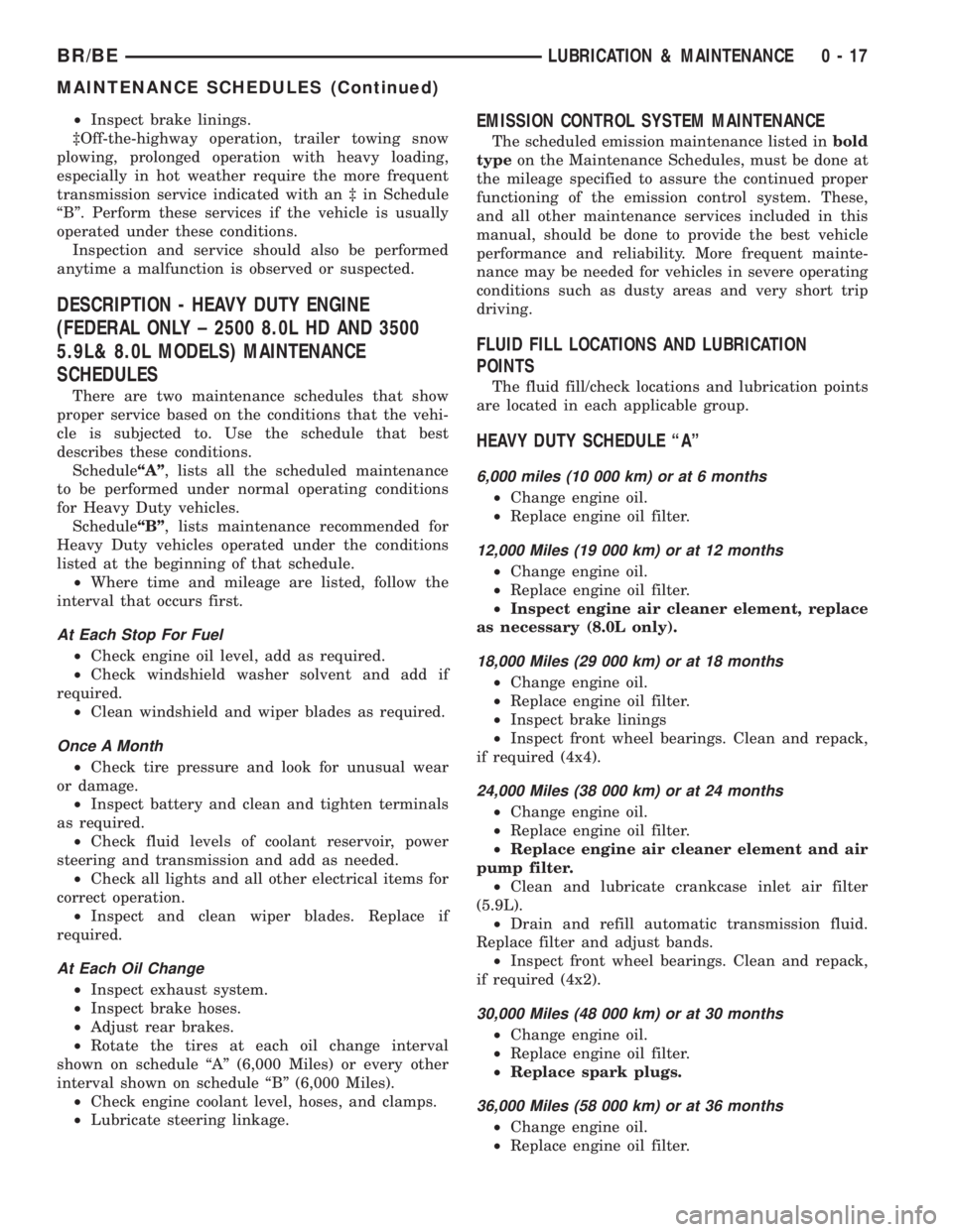
HEAVY DUTY SCHEDULE ªAº
6,000 miles (10 000 km) or at 6 months
²Change engine oil.
²Replace engine oil filter.
12,000 Miles (19 000 km) or at 12 months
²Change engine oil.
²Replace engine oil filter.
²Inspect engine air cleaner element, replace
as necessary (8.0L only).
18,000 Miles (29 000 km) or at 18 months
²Change engine oil.
²Replace engine oil filter.
²Inspect brake linings
²Inspect front wheel bearings. Clean and repack,
if required (4x4).
24,000 Miles (38 000 km) or at 24 months
²Change engine oil.
²Replace engine oil filter.
²Replace engine air cleaner element and air
pump filter.
²Clean and lubricate crankcase inlet air filter
(5.9L).
²Drain and refill automatic transmission fluid.
Replace filter and adjust bands.
²Inspect front wheel bearings. Clean and repack,
if required (4x2).
30,000 Miles (48 000 km) or at 30 months
²Change engine oil.
²Replace engine oil filter.
²Replace spark plugs.
36,000 Miles (58 000 km) or at 36 months
²Change engine oil.
²Replace engine oil filter.
BR/BELUBRICATION & MAINTENANCE 0 - 17
MAINTENANCE SCHEDULES (Continued)
Page 35 of 2889
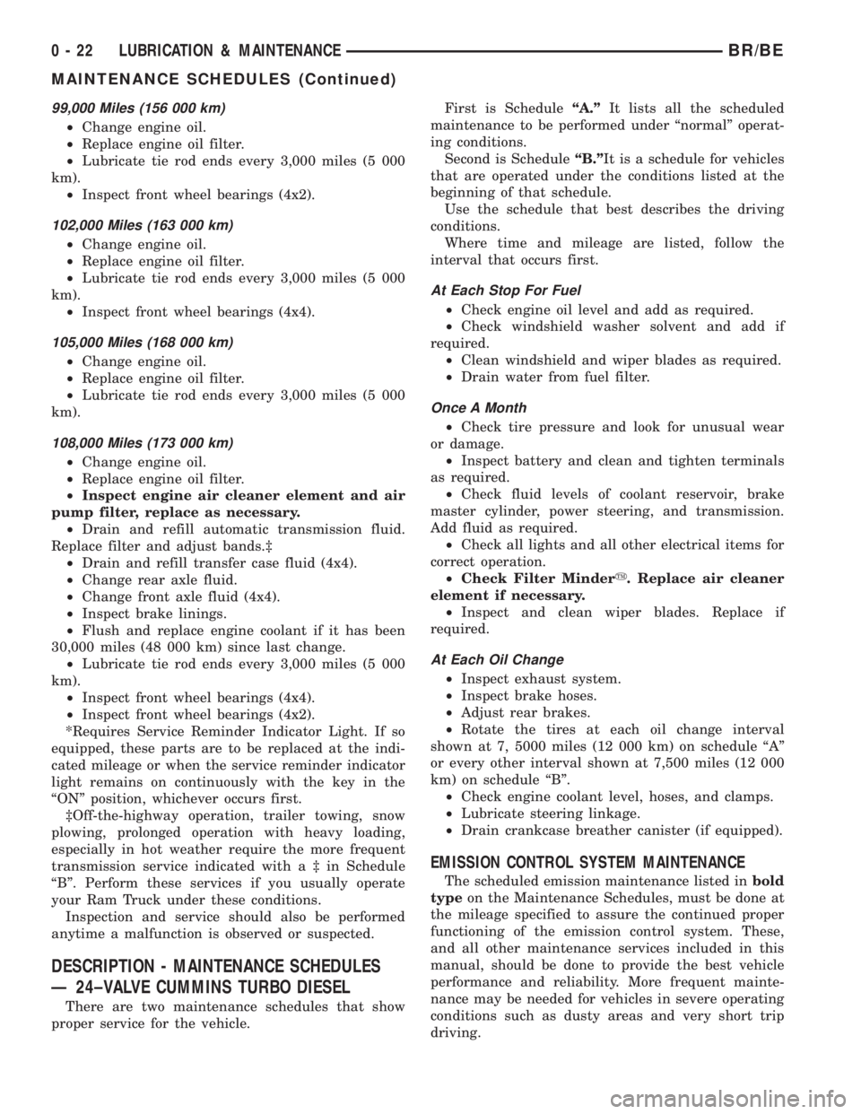
99,000 Miles (156 000 km)
²Change engine oil.
²Replace engine oil filter.
²Lubricate tie rod ends every 3,000 miles (5 000
km).
²Inspect front wheel bearings (4x2).
102,000 Miles (163 000 km)
²Change engine oil.
²Replace engine oil filter.
²Lubricate tie rod ends every 3,000 miles (5 000
km).
²Inspect front wheel bearings (4x4).
105,000 Miles (168 000 km)
²Change engine oil.
²Replace engine oil filter.
²Lubricate tie rod ends every 3,000 miles (5 000
km).
108,000 Miles (173 000 km)
²Change engine oil.
²Replace engine oil filter.
²Inspect engine air cleaner element and air
pump filter, replace as necessary.
²Drain and refill automatic transmission fluid.
Replace filter and adjust bands.³
²Drain and refill transfer case fluid (4x4).
²Change rear axle fluid.
²Change front axle fluid (4x4).
²Inspect brake linings.
²Flush and replace engine coolant if it has been
30,000 miles (48 000 km) since last change.
²Lubricate tie rod ends every 3,000 miles (5 000
km).
²Inspect front wheel bearings (4x4).
²Inspect front wheel bearings (4x2).
*Requires Service Reminder Indicator Light. If so
equipped, these parts are to be replaced at the indi-
cated mileage or when the service reminder indicator
light remains on continuously with the key in the
ªONº position, whichever occurs first.
³Off-the-highway operation, trailer towing, snow
plowing, prolonged operation with heavy loading,
especially in hot weather require the more frequent
transmission service indicated witha³inSchedule
ªBº. Perform these services if you usually operate
your Ram Truck under these conditions.
Inspection and service should also be performed
anytime a malfunction is observed or suspected.
DESCRIPTION - MAINTENANCE SCHEDULES
Ð 24±VALVE CUMMINS TURBO DIESEL
There are two maintenance schedules that show
proper service for the vehicle.First is ScheduleªA.ºIt lists all the scheduled
maintenance to be performed under ªnormalº operat-
ing conditions.
Second is ScheduleªB.ºIt is a schedule for vehicles
that are operated under the conditions listed at the
beginning of that schedule.
Use the schedule that best describes the driving
conditions.
Where time and mileage are listed, follow the
interval that occurs first.
At Each Stop For Fuel
²Check engine oil level and add as required.
²Check windshield washer solvent and add if
required.
²Clean windshield and wiper blades as required.
²Drain water from fuel filter.
Once A Month
²Check tire pressure and look for unusual wear
or damage.
²Inspect battery and clean and tighten terminals
as required.
²Check fluid levels of coolant reservoir, brake
master cylinder, power steering, and transmission.
Add fluid as required.
²Check all lights and all other electrical items for
correct operation.
²Check Filter Mindery. Replace air cleaner
element if necessary.
²Inspect and clean wiper blades. Replace if
required.
At Each Oil Change
²Inspect exhaust system.
²Inspect brake hoses.
²Adjust rear brakes.
²Rotate the tires at each oil change interval
shown at 7, 5000 miles (12 000 km) on schedule ªAº
or every other interval shown at 7,500 miles (12 000
km) on schedule ªBº.
²Check engine coolant level, hoses, and clamps.
²Lubricate steering linkage.
²Drain crankcase breather canister (if equipped).
EMISSION CONTROL SYSTEM MAINTENANCE
The scheduled emission maintenance listed inbold
typeon the Maintenance Schedules, must be done at
the mileage specified to assure the continued proper
functioning of the emission control system. These,
and all other maintenance services included in this
manual, should be done to provide the best vehicle
performance and reliability. More frequent mainte-
nance may be needed for vehicles in severe operating
conditions such as dusty areas and very short trip
driving.
0 - 22 LUBRICATION & MAINTENANCEBR/BE
MAINTENANCE SCHEDULES (Continued)
Page 36 of 2889
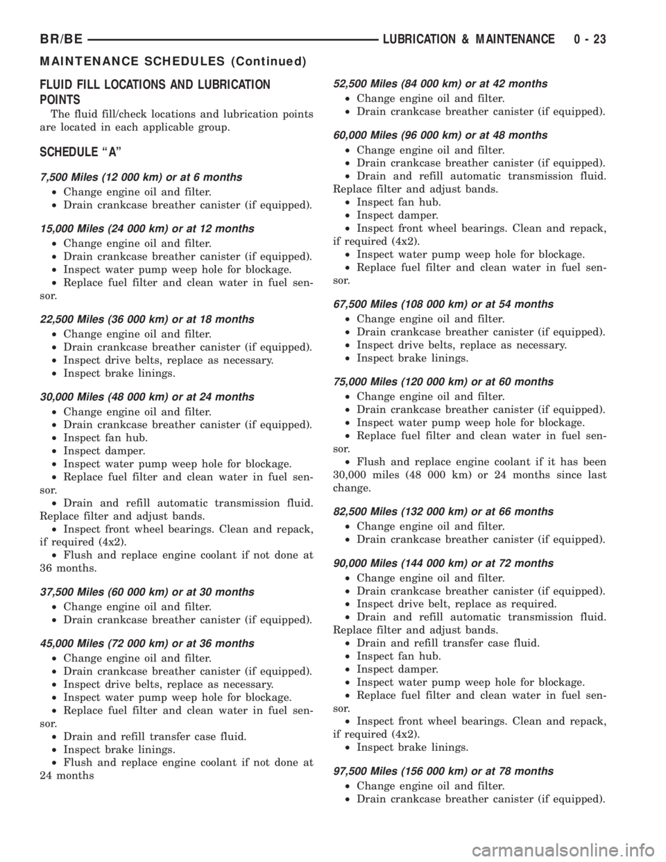
FLUID FILL LOCATIONS AND LUBRICATION
POINTS
The fluid fill/check locations and lubrication points
are located in each applicable group.
SCHEDULE ªAº
7,500 Miles (12 000 km) or at 6 months
²Change engine oil and filter.
²Drain crankcase breather canister (if equipped).
15,000 Miles (24 000 km) or at 12 months
²Change engine oil and filter.
²Drain crankcase breather canister (if equipped).
²Inspect water pump weep hole for blockage.
²Replace fuel filter and clean water in fuel sen-
sor.
22,500 Miles (36 000 km) or at 18 months
²Change engine oil and filter.
²Drain crankcase breather canister (if equipped).
²Inspect drive belts, replace as necessary.
²Inspect brake linings.
30,000 Miles (48 000 km) or at 24 months
²Change engine oil and filter.
²Drain crankcase breather canister (if equipped).
²Inspect fan hub.
²Inspect damper.
²Inspect water pump weep hole for blockage.
²Replace fuel filter and clean water in fuel sen-
sor.
²Drain and refill automatic transmission fluid.
Replace filter and adjust bands.
²Inspect front wheel bearings. Clean and repack,
if required (4x2).
²Flush and replace engine coolant if not done at
36 months.
37,500 Miles (60 000 km) or at 30 months
²Change engine oil and filter.
²Drain crankcase breather canister (if equipped).
45,000 Miles (72 000 km) or at 36 months
²Change engine oil and filter.
²Drain crankcase breather canister (if equipped).
²Inspect drive belts, replace as necessary.
²Inspect water pump weep hole for blockage.
²Replace fuel filter and clean water in fuel sen-
sor.
²Drain and refill transfer case fluid.
²Inspect brake linings.
²Flush and replace engine coolant if not done at
24 months
52,500 Miles (84 000 km) or at 42 months
²Change engine oil and filter.
²Drain crankcase breather canister (if equipped).
60,000 Miles (96 000 km) or at 48 months
²Change engine oil and filter.
²Drain crankcase breather canister (if equipped).
²Drain and refill automatic transmission fluid.
Replace filter and adjust bands.
²Inspect fan hub.
²Inspect damper.
²Inspect front wheel bearings. Clean and repack,
if required (4x2).
²Inspect water pump weep hole for blockage.
²Replace fuel filter and clean water in fuel sen-
sor.
67,500 Miles (108 000 km) or at 54 months
²Change engine oil and filter.
²Drain crankcase breather canister (if equipped).
²Inspect drive belts, replace as necessary.
²Inspect brake linings.
75,000 Miles (120 000 km) or at 60 months
²Change engine oil and filter.
²Drain crankcase breather canister (if equipped).
²Inspect water pump weep hole for blockage.
²Replace fuel filter and clean water in fuel sen-
sor.
²Flush and replace engine coolant if it has been
30,000 miles (48 000 km) or 24 months since last
change.
82,500 Miles (132 000 km) or at 66 months
²Change engine oil and filter.
²Drain crankcase breather canister (if equipped).
90,000 Miles (144 000 km) or at 72 months
²Change engine oil and filter.
²Drain crankcase breather canister (if equipped).
²Inspect drive belt, replace as required.
²Drain and refill automatic transmission fluid.
Replace filter and adjust bands.
²Drain and refill transfer case fluid.
²Inspect fan hub.
²Inspect damper.
²Inspect water pump weep hole for blockage.
²Replace fuel filter and clean water in fuel sen-
sor.
²Inspect front wheel bearings. Clean and repack,
if required (4x2).
²Inspect brake linings.
97,500 Miles (156 000 km) or at 78 months
²Change engine oil and filter.
²Drain crankcase breather canister (if equipped).
BR/BELUBRICATION & MAINTENANCE 0 - 23
MAINTENANCE SCHEDULES (Continued)
Page 48 of 2889
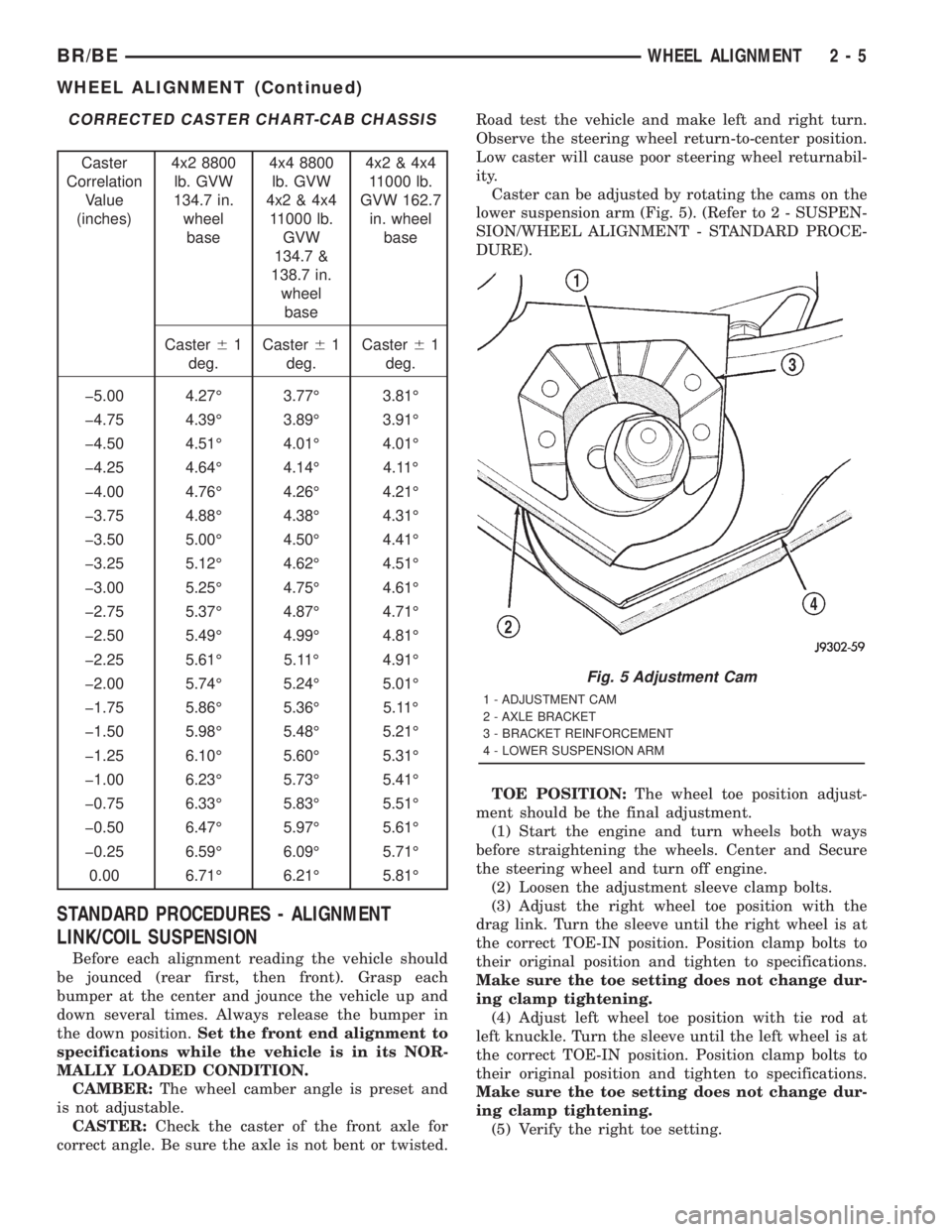
CORRECTED CASTER CHART-CAB CHASSIS
Caster
Correlation
Value
(inches)4x2 8800
lb. GVW
134.7 in.
wheel
base4x4 8800
lb. GVW
4x2 & 4x4
11000 lb.
GVW
134.7 &
138.7 in.
wheel
base4x2 & 4x4
11000 lb.
GVW 162.7
in. wheel
base
Caster61
deg.Caster61
deg.Caster61
deg.
þ5.00 4.27É 3.77É 3.81É
þ4.75 4.39É 3.89É 3.91É
þ4.50 4.51É 4.01É 4.01É
þ4.25 4.64É 4.14É 4.11É
þ4.00 4.76É 4.26É 4.21É
þ3.75 4.88É 4.38É 4.31É
þ3.50 5.00É 4.50É 4.41É
þ3.25 5.12É 4.62É 4.51É
þ3.00 5.25É 4.75É 4.61É
þ2.75 5.37É 4.87É 4.71É
þ2.50 5.49É 4.99É 4.81É
þ2.25 5.61É 5.11É 4.91É
þ2.00 5.74É 5.24É 5.01É
þ1.75 5.86É 5.36É 5.11É
þ1.50 5.98É 5.48É 5.21É
þ1.25 6.10É 5.60É 5.31É
þ1.00 6.23É 5.73É 5.41É
þ0.75 6.33É 5.83É 5.51É
þ0.50 6.47É 5.97É 5.61É
þ0.25 6.59É 6.09É 5.71É
0.00 6.71É 6.21É 5.81É
STANDARD PROCEDURES - ALIGNMENT
LINK/COIL SUSPENSION
Before each alignment reading the vehicle should
be jounced (rear first, then front). Grasp each
bumper at the center and jounce the vehicle up and
down several times. Always release the bumper in
the down position.Set the front end alignment to
specifications while the vehicle is in its NOR-
MALLY LOADED CONDITION.
CAMBER:The wheel camber angle is preset and
is not adjustable.
CASTER:Check the caster of the front axle for
correct angle. Be sure the axle is not bent or twisted.Road test the vehicle and make left and right turn.
Observe the steering wheel return-to-center position.
Low caster will cause poor steering wheel returnabil-
ity.
Caster can be adjusted by rotating the cams on the
lower suspension arm (Fig. 5). (Refer to 2 - SUSPEN-
SION/WHEEL ALIGNMENT - STANDARD PROCE-
DURE).
TOE POSITION:The wheel toe position adjust-
ment should be the final adjustment.
(1) Start the engine and turn wheels both ways
before straightening the wheels. Center and Secure
the steering wheel and turn off engine.
(2) Loosen the adjustment sleeve clamp bolts.
(3) Adjust the right wheel toe position with the
drag link. Turn the sleeve until the right wheel is at
the correct TOE-IN position. Position clamp bolts to
their original position and tighten to specifications.
Make sure the toe setting does not change dur-
ing clamp tightening.
(4) Adjust left wheel toe position with tie rod at
left knuckle. Turn the sleeve until the left wheel is at
the correct TOE-IN position. Position clamp bolts to
their original position and tighten to specifications.
Make sure the toe setting does not change dur-
ing clamp tightening.
(5) Verify the right toe setting.
Fig. 5 Adjustment Cam
1 - ADJUSTMENT CAM
2 - AXLE BRACKET
3 - BRACKET REINFORCEMENT
4 - LOWER SUSPENSION ARM
BR/BEWHEEL ALIGNMENT 2 - 5
WHEEL ALIGNMENT (Continued)
Page 52 of 2889
SPECIAL TOOLS
INDEPENDENT FRONT SUSPENSION
HUB / BEARING
REMOVAL
(1) Raise and support the vehicle.
(2) Remove the wheel and tire assembly.
(3) Remove the caliper adapter bolts from the
steering knuckle and remove caliper adapter assem-
bly (Refer to 5 - BRAKES/HYDRAULIC/MECHANI-
CAL/DISC BRAKE CALIPERS - REMOVAL).
NOTE: Do not allow brake hose to support caliper
adapter assembly.
(4) Remove the rotor from the hub/bearing wheel
studs.
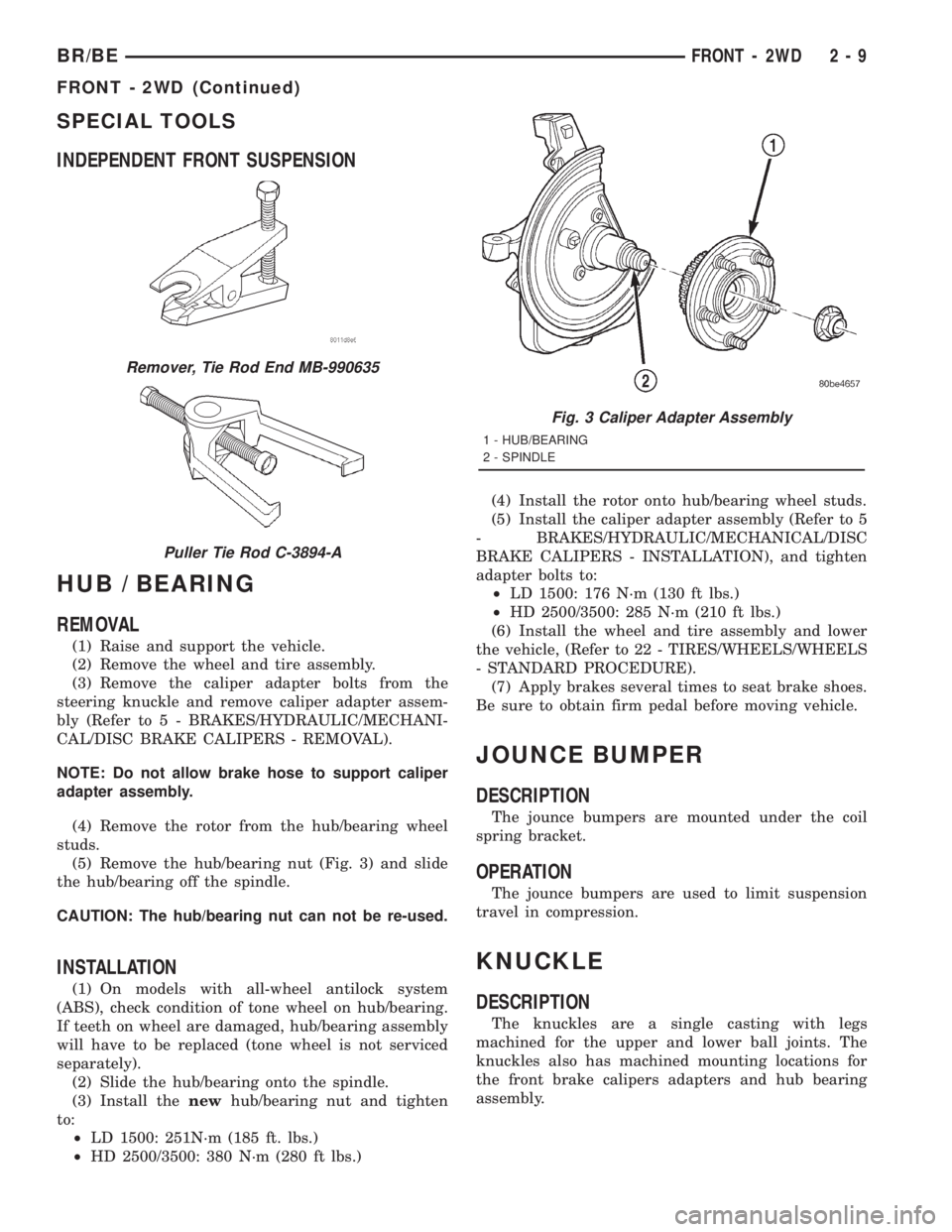
(5) Remove the hub/bearing nut (Fig. 3) and slide
the hub/bearing off the spindle.
CAUTION: The hub/bearing nut can not be re-used.
INSTALLATION
(1) On models with all-wheel antilock system
(ABS), check condition of tone wheel on hub/bearing.
If teeth on wheel are damaged, hub/bearing assembly
will have to be replaced (tone wheel is not serviced
separately).
(2) Slide the hub/bearing onto the spindle.
(3) Install thenewhub/bearing nut and tighten
to:
²LD 1500: 251N´m (185 ft. lbs.)
²HD 2500/3500: 380 N´m (280 ft lbs.)(4) Install the rotor onto hub/bearing wheel studs.
(5) Install the caliper adapter assembly (Refer to 5
- BRAKES/HYDRAULIC/MECHANICAL/DISC
BRAKE CALIPERS - INSTALLATION), and tighten
adapter bolts to:
²LD 1500: 176 N´m (130 ft lbs.)
²HD 2500/3500: 285 N´m (210 ft lbs.)
(6) Install the wheel and tire assembly and lower
the vehicle, (Refer to 22 - TIRES/WHEELS/WHEELS
- STANDARD PROCEDURE).
(7) Apply brakes several times to seat brake shoes.
Be sure to obtain firm pedal before moving vehicle.
JOUNCE BUMPER
DESCRIPTION
The jounce bumpers are mounted under the coil
spring bracket.
OPERATION
The jounce bumpers are used to limit suspension
travel in compression.
KNUCKLE
DESCRIPTION
The knuckles are a single casting with legs
machined for the upper and lower ball joints. The
knuckles also has machined mounting locations for
the front brake calipers adapters and hub bearing
assembly.
Remover, Tie Rod End MB-990635
Puller Tie Rod C-3894-A
Fig. 3 Caliper Adapter Assembly
1 - HUB/BEARING
2 - SPINDLE
BR/BEFRONT - 2WD 2 - 9
FRONT - 2WD (Continued)
Page 54 of 2889
(5) Install the steering knuckle on the lower ball
joint. Install the lower ball joint nut and tighten to:
²LD: 129 N´m (95 ft. lbs.)
²HD: 136 N´m (110 ft. lbs.)
(5) Install the lower ball joint cotter pin.
(6) Install the stabilizer bar link on the lower sus-
pension arm. Install the grommet, retainer and nut
and tighten to 37 N´m (27 ft. lbs.).
(7) Install the tie rod end on the steering knuckle
and tighten nut to 108 N´m (80 ft. lbs.). Install cotter
pin.
(8) Install the brake rotor and caliper assembly,
(Refer to 5 - BRAKES/HYDRAULIC/MECHANICAL/
ROTORS - INSTALLATION).
(9) Install the tire and wheel assembly, (Refer to
22 - TIRES/WHEELS/WHEELS - STANDARD PRO-
CEDURE).
(10) Remove the support and lower the vehicle.
(11) Tighten the suspension arm crossmember
nuts to 169 N´m (125 ft. lbs.).
SHOCK
DESCRIPTION
The top of the shocks mounts on frame brackets
using grommets. The bottom of the shock is bolted to
the lower suspension arms.
OPERATION
The shock absorbers dampen jounce and rebound
of the vehicle over various road conditions.
DIAGNOSIS AND TESTING - SHOCK
A knocking or rattling noise from a shock absorber
may be caused by movement between mounting
bushings and metal brackets or attaching compo-
nents. These noises can usually be stopped by tight-
ening the attaching nuts. If the noise persists,
inspect for damaged and worn bushings, and attach-
ing components. Repair as necessary if any of these
conditions exist.
A squeaking noise from the shock absorber may be
caused by the hydraulic valving and may be intermit-
tent. This condition is not repairable and the shock
absorber must be replaced.
The shock absorbers are not refillable or adjust-
able. If a malfunction occurs, the shock absorber
must be replaced. To test a shock absorber, hold it in
an upright position and force the piston in and out of
the cylinder four or five times. The action throughout
each stroke should be smooth and even.
The shock absorber bushings do not require any
type of lubrication. Do not attempt to stop bushing
noise by lubricating them. Grease and mineral oil-
base lubricants will deteriorate the bushing.
REMOVAL
(1) Raise and support vehicle.
(2) Remove shock upper nut and remove retainer
and grommet.
(3) Remove lower mounting bolt from suspension
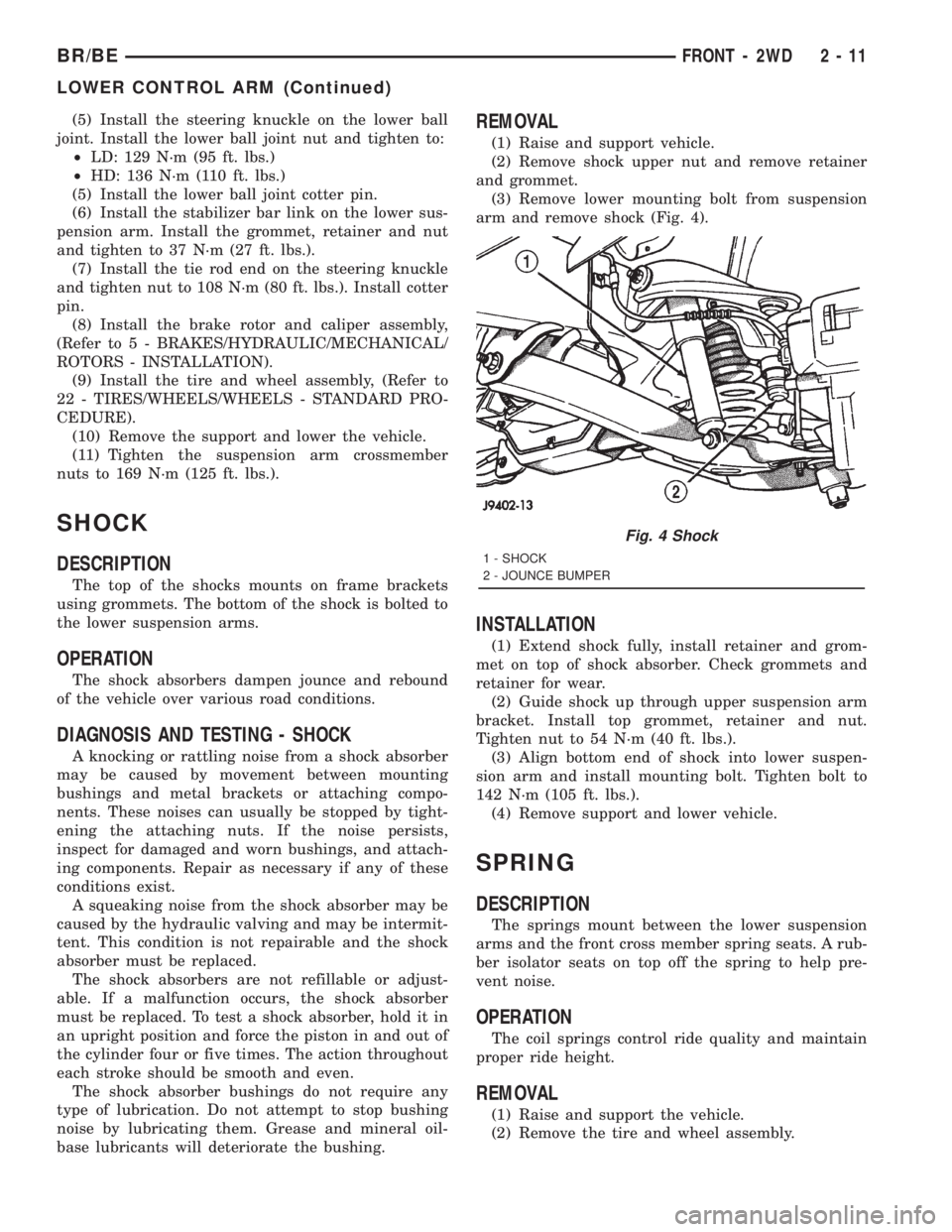
arm and remove shock (Fig. 4).
INSTALLATION
(1) Extend shock fully, install retainer and grom-
met on top of shock absorber. Check grommets and
retainer for wear.
(2) Guide shock up through upper suspension arm
bracket. Install top grommet, retainer and nut.
Tighten nut to 54 N´m (40 ft. lbs.).
(3) Align bottom end of shock into lower suspen-
sion arm and install mounting bolt. Tighten bolt to
142 N´m (105 ft. lbs.).
(4) Remove support and lower vehicle.
SPRING
DESCRIPTION
The springs mount between the lower suspension
arms and the front cross member spring seats. A rub-
ber isolator seats on top off the spring to help pre-
vent noise.
OPERATION
The coil springs control ride quality and maintain
proper ride height.
REMOVAL
(1) Raise and support the vehicle.
(2) Remove the tire and wheel assembly.
Fig. 4 Shock
1 - SHOCK
2 - JOUNCE BUMPER
BR/BEFRONT - 2WD 2 - 11
LOWER CONTROL ARM (Continued)
Page 69 of 2889
REAR
TABLE OF CONTENTS
page page
REAR
DESCRIPTION...........................26
DIAGNOSIS AND TESTING.................26
SPRING AND SHOCK....................26
SPECIFICATIONS........................27
SPECIAL TOOLS.........................28
BUSHINGS
REMOVAL..............................28
INSTALLATION...........................28
JOUNCE BUMPER
DESCRIPTION...........................28
OPERATION.............................28
SHOCK
DESCRIPTION...........................28OPERATION.............................28
REMOVAL..............................28
INSTALLATION...........................28
SPRING
DESCRIPTION...........................28
OPERATION.............................28
REMOVAL..............................28
INSTALLATION...........................29
STABILIZER BAR
DESCRIPTION...........................30
OPERATION.............................30
REMOVAL..............................30
INSTALLATION...........................30
REAR
DESCRIPTION
The rear suspension is comprised of:
²Shock Absorbers
²Jounce Bumpers
²Stabilizer Bar (optional)
²Leaf Springs
²Drive Axle
CAUTION: A vehicle should always be loaded so
the vehicle weight center-line is located immedi-
ately forward of the rear axle. Correct vehicle load-
ing provides proper front tire-to-road contact. This
results in maximum vehicle handling stability and
safety. Incorrect vehicle weight distribution can
cause excessive tire tread wear, spring fatigue or
failure, and erratic steering.
CAUTION: Suspension components with rubber/ure-
thane bushings (except stabilizer bar) should be
tightened with the vehicle at normal ride height. It is
important to have the springs supporting the weight
of the vehicle when the fasteners are torqued. If
springs are not at their normal ride position, vehicle
ride comfort could be affected and premature bush-
ing wear may occur.
DIAGNOSIS AND TESTING - SPRING AND
SHOCK
A knocking or rattling noise from a shock absorber
may be caused by movement between mounting
bushings and metal brackets or attaching compo-
nents. These noises can usually be stopped by tight-
ening the attaching nuts. If the noise persists,
inspect for damaged and worn bushings, and attach-
ing components. Repair as necessary if any of these
conditions exist.
A squeaking noise from the shock absorber may be
caused by the hydraulic valving and may be intermit-
tent. This condition is not repairable and the shock
absorber must be replaced.
The shock absorbers are not refillable or adjust-
able. If a malfunction occurs, the shock absorber
must be replaced. To test a shock absorber, hold it in
an upright position and force the piston in and out of
the cylinder four or five times. The action throughout
each stroke should be smooth and even.
The spring eye and shock absorber bushings do not
require any type of lubrication. Do not attempt to
stop spring bushing noise by lubricating them.
Grease and mineral oil-base lubricants will deterio-
rate the bushing rubber.
If the vehicle is used for severe, off-road operation,
the springs should be examined periodically. Check
for broken and shifted leafs, loose and missing clips,
and broken center bolts. Refer to Spring and Shock
Absorber Diagnosis chart for additional information.
2 - 26 REARBR/BE