2001 DODGE RAM transmission oil
[x] Cancel search: transmission oilPage 1903 of 2889
REGULATOR VALVE
The pressure regulator valve is needed to control
the hydraulic pressure within the system and reduce
the amount of heat produced in the fluid. The pres-
sure regulator valve is located in the valve body near
the manual valve. The pressure regulator valve train
controls the maximum pressure in the lines by
metering the dumping of fluid back into the sump.
Regulated pressure is referred to as ªline pressure.º
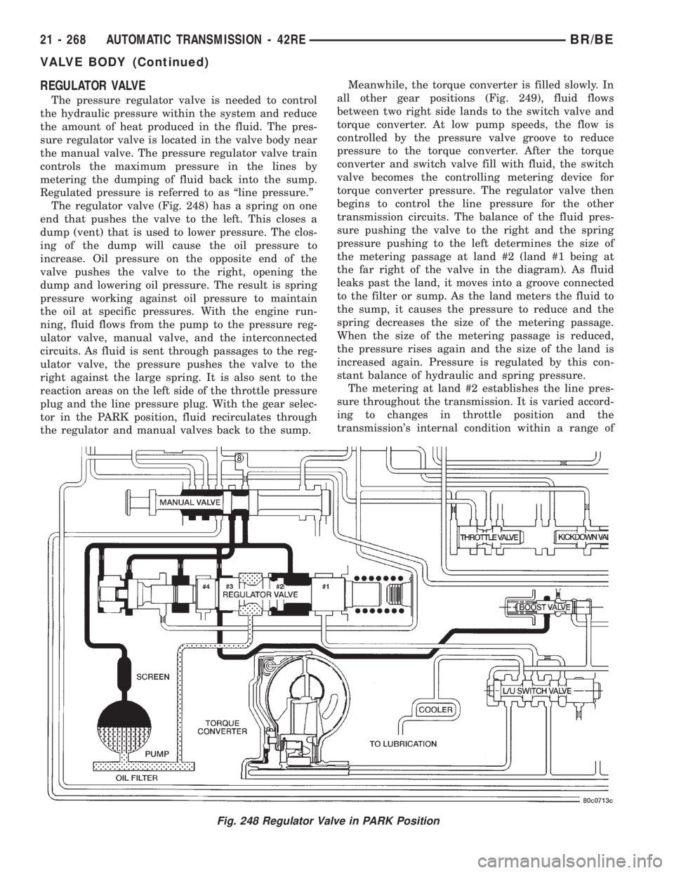
The regulator valve (Fig. 248) has a spring on one
end that pushes the valve to the left. This closes a
dump (vent) that is used to lower pressure. The clos-
ing of the dump will cause the oil pressure to
increase. Oil pressure on the opposite end of the
valve pushes the valve to the right, opening the
dump and lowering oil pressure. The result is spring
pressure working against oil pressure to maintain
the oil at specific pressures. With the engine run-
ning, fluid flows from the pump to the pressure reg-
ulator valve, manual valve, and the interconnected
circuits. As fluid is sent through passages to the reg-
ulator valve, the pressure pushes the valve to the
right against the large spring. It is also sent to the
reaction areas on the left side of the throttle pressure
plug and the line pressure plug. With the gear selec-
tor in the PARK position, fluid recirculates through
the regulator and manual valves back to the sump.Meanwhile, the torque converter is filled slowly. In
all other gear positions (Fig. 249), fluid flows
between two right side lands to the switch valve and
torque converter. At low pump speeds, the flow is
controlled by the pressure valve groove to reduce
pressure to the torque converter. After the torque
converter and switch valve fill with fluid, the switch
valve becomes the controlling metering device for
torque converter pressure. The regulator valve then
begins to control the line pressure for the other
transmission circuits. The balance of the fluid pres-
sure pushing the valve to the right and the spring
pressure pushing to the left determines the size of
the metering passage at land #2 (land #1 being at
the far right of the valve in the diagram). As fluid
leaks past the land, it moves into a groove connected
to the filter or sump. As the land meters the fluid to
the sump, it causes the pressure to reduce and the
spring decreases the size of the metering passage.
When the size of the metering passage is reduced,
the pressure rises again and the size of the land is
increased again. Pressure is regulated by this con-
stant balance of hydraulic and spring pressure.
The metering at land #2 establishes the line pres-
sure throughout the transmission. It is varied accord-
ing to changes in throttle position and the
transmission's internal condition within a range of
Fig. 248 Regulator Valve in PARK Position
21 - 268 AUTOMATIC TRANSMISSION - 42REBR/BE
VALVE BODY (Continued)
Page 1913 of 2889
SWITCH VALVE
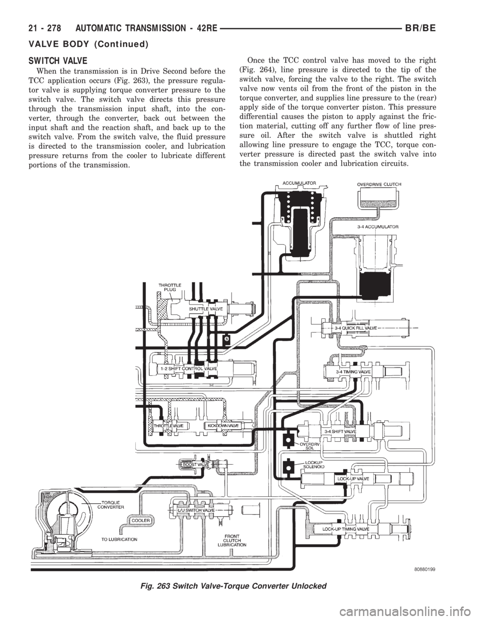
When the transmission is in Drive Second before the
TCC application occurs (Fig. 263), the pressure regula-
tor valve is supplying torque converter pressure to the
switch valve. The switch valve directs this pressure
through the transmission input shaft, into the con-
verter, through the converter, back out between the
input shaft and the reaction shaft, and back up to the
switch valve. From the switch valve, the fluid pressure
is directed to the transmission cooler, and lubrication
pressure returns from the cooler to lubricate different
portions of the transmission.Once the TCC control valve has moved to the right
(Fig. 264), line pressure is directed to the tip of the
switch valve, forcing the valve to the right. The switch
valve now vents oil from the front of the piston in the
torque converter, and supplies line pressure to the (rear)
apply side of the torque converter piston. This pressure
differential causes the piston to apply against the fric-
tion material, cutting off any further flow of line pres-
sure oil. After the switch valve is shuttled right
allowing line pressure to engage the TCC, torque con-
verter pressure is directed past the switch valve into
the transmission cooler and lubrication circuits.
Fig. 263 Switch Valve-Torque Converter Unlocked
21 - 278 AUTOMATIC TRANSMISSION - 42REBR/BE
VALVE BODY (Continued)
Page 1916 of 2889
BOOST VALVE
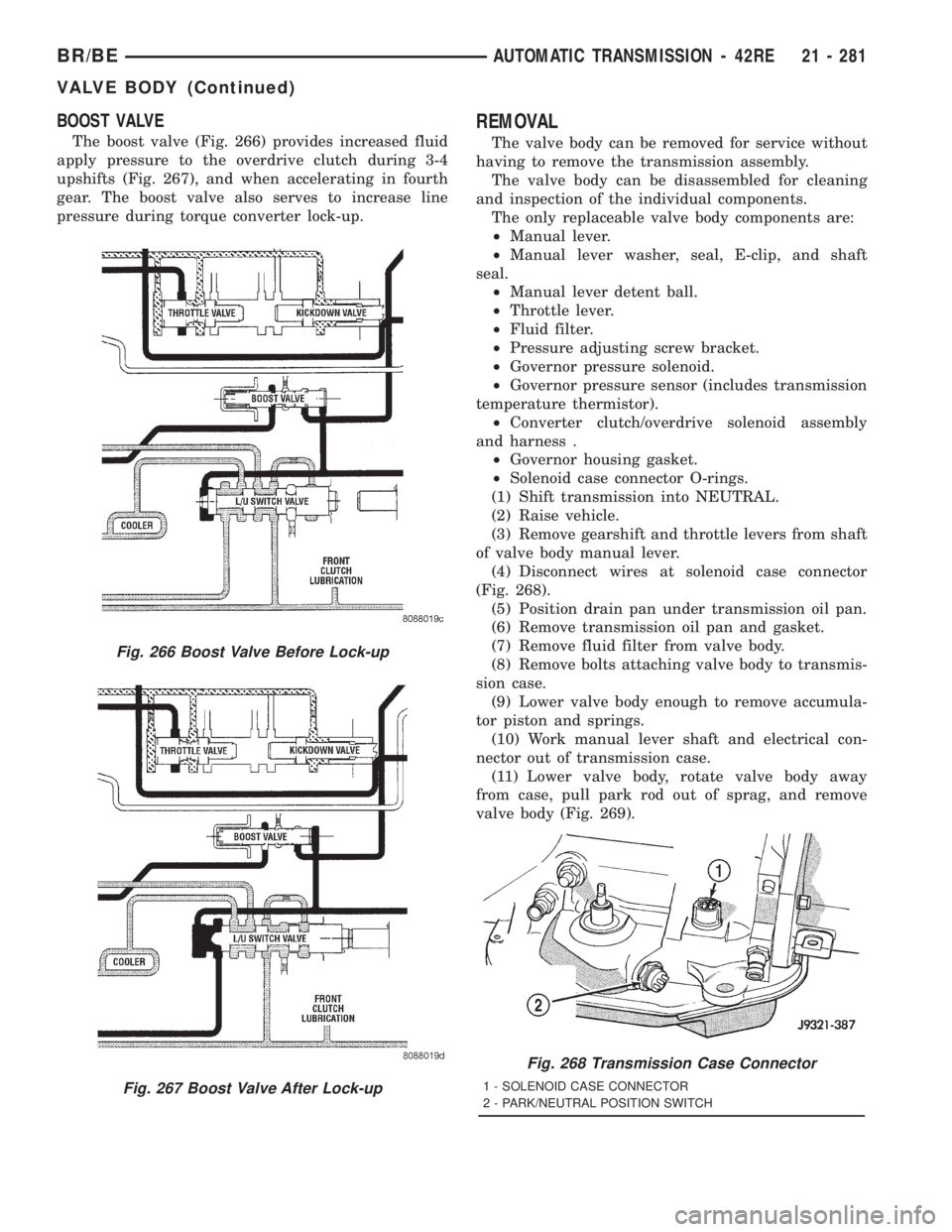
The boost valve (Fig. 266) provides increased fluid
apply pressure to the overdrive clutch during 3-4
upshifts (Fig. 267), and when accelerating in fourth
gear. The boost valve also serves to increase line
pressure during torque converter lock-up.
REMOVAL
The valve body can be removed for service without
having to remove the transmission assembly.
The valve body can be disassembled for cleaning
and inspection of the individual components.
The only replaceable valve body components are:
²Manual lever.
²Manual lever washer, seal, E-clip, and shaft
seal.
²Manual lever detent ball.
²Throttle lever.
²Fluid filter.
²Pressure adjusting screw bracket.
²Governor pressure solenoid.
²Governor pressure sensor (includes transmission
temperature thermistor).
²Converter clutch/overdrive solenoid assembly
and harness .
²Governor housing gasket.
²Solenoid case connector O-rings.
(1) Shift transmission into NEUTRAL.
(2) Raise vehicle.
(3) Remove gearshift and throttle levers from shaft
of valve body manual lever.
(4) Disconnect wires at solenoid case connector
(Fig. 268).
(5) Position drain pan under transmission oil pan.
(6) Remove transmission oil pan and gasket.
(7) Remove fluid filter from valve body.
(8) Remove bolts attaching valve body to transmis-
sion case.
(9) Lower valve body enough to remove accumula-
tor piston and springs.
(10) Work manual lever shaft and electrical con-
nector out of transmission case.
(11) Lower valve body, rotate valve body away
from case, pull park rod out of sprag, and remove
valve body (Fig. 269).
Fig. 266 Boost Valve Before Lock-up
Fig. 267 Boost Valve After Lock-up
Fig. 268 Transmission Case Connector
1 - SOLENOID CASE CONNECTOR
2 - PARK/NEUTRAL POSITION SWITCH
BR/BEAUTOMATIC TRANSMISSION - 42RE 21 - 281
VALVE BODY (Continued)
Page 1928 of 2889
3-4 ACCUMULATOR HOUSING
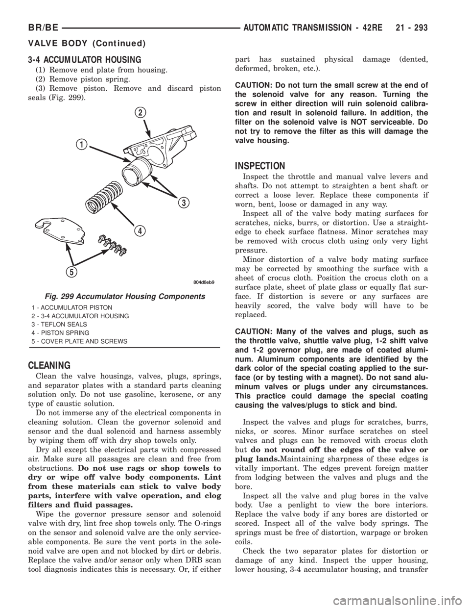
(1) Remove end plate from housing.
(2) Remove piston spring.
(3) Remove piston. Remove and discard piston
seals (Fig. 299).
CLEANING
Clean the valve housings, valves, plugs, springs,
and separator plates with a standard parts cleaning
solution only. Do not use gasoline, kerosene, or any
type of caustic solution.
Do not immerse any of the electrical components in
cleaning solution. Clean the governor solenoid and
sensor and the dual solenoid and harness assembly
by wiping them off with dry shop towels only.
Dry all except the electrical parts with compressed
air. Make sure all passages are clean and free from
obstructions.Do not use rags or shop towels to
dry or wipe off valve body components. Lint
from these materials can stick to valve body
parts, interfere with valve operation, and clog
filters and fluid passages.
Wipe the governor pressure sensor and solenoid
valve with dry, lint free shop towels only. The O-rings
on the sensor and solenoid valve are the only service-
able components. Be sure the vent ports in the sole-
noid valve are open and not blocked by dirt or debris.
Replace the valve and/or sensor only when DRB scan
tool diagnosis indicates this is necessary. Or, if eitherpart has sustained physical damage (dented,
deformed, broken, etc.).
CAUTION: Do not turn the small screw at the end of
the solenoid valve for any reason. Turning the
screw in either direction will ruin solenoid calibra-
tion and result in solenoid failure. In addition, the
filter on the solenoid valve is NOT serviceable. Do
not try to remove the filter as this will damage the
valve housing.
INSPECTION
Inspect the throttle and manual valve levers and
shafts. Do not attempt to straighten a bent shaft or
correct a loose lever. Replace these components if
worn, bent, loose or damaged in any way.
Inspect all of the valve body mating surfaces for
scratches, nicks, burrs, or distortion. Use a straight-
edge to check surface flatness. Minor scratches may
be removed with crocus cloth using only very light
pressure.
Minor distortion of a valve body mating surface
may be corrected by smoothing the surface with a
sheet of crocus cloth. Position the crocus cloth on a
surface plate, sheet of plate glass or equally flat sur-
face. If distortion is severe or any surfaces are
heavily scored, the valve body will have to be
replaced.
CAUTION: Many of the valves and plugs, such as
the throttle valve, shuttle valve plug, 1-2 shift valve
and 1-2 governor plug, are made of coated alumi-
num. Aluminum components are identified by the
dark color of the special coating applied to the sur-
face (or by testing with a magnet). Do not sand alu-
minum valves or plugs under any circumstances.
This practice could damage the special coating
causing the valves/plugs to stick and bind.
Inspect the valves and plugs for scratches, burrs,
nicks, or scores. Minor surface scratches on steel
valves and plugs can be removed with crocus cloth
butdo not round off the edges of the valve or
plug lands.Maintaining sharpness of these edges is
vitally important. The edges prevent foreign matter
from lodging between the valves and plugs and the
bore.
Inspect all the valve and plug bores in the valve
body. Use a penlight to view the bore interiors.
Replace the valve body if any bores are distorted or
scored. Inspect all of the valve body springs. The
springs must be free of distortion, warpage or broken
coils.
Check the two separator plates for distortion or
damage of any kind. Inspect the upper housing,
lower housing, 3-4 accumulator housing, and transfer
Fig. 299 Accumulator Housing Components
1 - ACCUMULATOR PISTON
2 - 3-4 ACCUMULATOR HOUSING
3 - TEFLON SEALS
4 - PISTON SPRING
5 - COVER PLATE AND SCREWS
BR/BEAUTOMATIC TRANSMISSION - 42RE 21 - 293
VALVE BODY (Continued)
Page 1938 of 2889
(7) Install retainer plate on governor body and
around solenoid. Be sure solenoid connector is posi-
tioned in retainer cutout.
(8) Align screw holes in governor body and trans-
fer plate. Then install and tighten governor body
screws to 4 N´m (35 in. lbs.) torque.
(9) Connect harness wires to governor pressure
solenoid and governor pressure sensor.
(10) Install fluid filter and pan.
(11) Lower vehicle.
(12) Fill transmission with recommended fluid and
road test vehicle to verify repair.
INSTALLATION
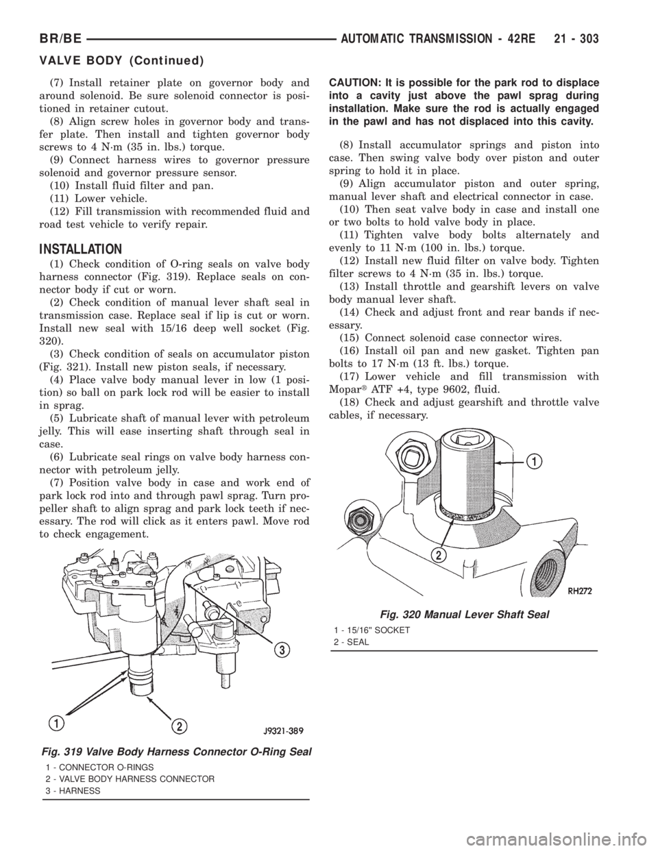
(1) Check condition of O-ring seals on valve body
harness connector (Fig. 319). Replace seals on con-
nector body if cut or worn.
(2) Check condition of manual lever shaft seal in
transmission case. Replace seal if lip is cut or worn.
Install new seal with 15/16 deep well socket (Fig.
320).
(3) Check condition of seals on accumulator piston
(Fig. 321). Install new piston seals, if necessary.
(4) Place valve body manual lever in low (1 posi-
tion) so ball on park lock rod will be easier to install
in sprag.
(5) Lubricate shaft of manual lever with petroleum
jelly. This will ease inserting shaft through seal in
case.
(6) Lubricate seal rings on valve body harness con-
nector with petroleum jelly.
(7) Position valve body in case and work end of
park lock rod into and through pawl sprag. Turn pro-
peller shaft to align sprag and park lock teeth if nec-
essary. The rod will click as it enters pawl. Move rod
to check engagement.CAUTION: It is possible for the park rod to displace
into a cavity just above the pawl sprag during
installation. Make sure the rod is actually engaged
in the pawl and has not displaced into this cavity.
(8) Install accumulator springs and piston into
case. Then swing valve body over piston and outer
spring to hold it in place.
(9) Align accumulator piston and outer spring,
manual lever shaft and electrical connector in case.
(10) Then seat valve body in case and install one
or two bolts to hold valve body in place.
(11) Tighten valve body bolts alternately and
evenly to 11 N´m (100 in. lbs.) torque.
(12) Install new fluid filter on valve body. Tighten
filter screws to 4 N´m (35 in. lbs.) torque.
(13) Install throttle and gearshift levers on valve
body manual lever shaft.
(14) Check and adjust front and rear bands if nec-
essary.
(15) Connect solenoid case connector wires.
(16) Install oil pan and new gasket. Tighten pan
bolts to 17 N´m (13 ft. lbs.) torque.
(17) Lower vehicle and fill transmission with
MopartATF +4, type 9602, fluid.
(18) Check and adjust gearshift and throttle valve
cables, if necessary.
Fig. 319 Valve Body Harness Connector O-Ring Seal
1 - CONNECTOR O-RINGS
2 - VALVE BODY HARNESS CONNECTOR
3 - HARNESS
Fig. 320 Manual Lever Shaft Seal
1 - 15/16©© SOCKET
2 - SEAL
BR/BEAUTOMATIC TRANSMISSION - 42RE 21 - 303
VALVE BODY (Continued)
Page 1940 of 2889
AUTOMATIC TRANSMISSION - 44RE
TABLE OF CONTENTS
page page
AUTOMATIC TRANSMISSION - 44RE
DESCRIPTION..........................306
OPERATION............................308
DIAGNOSIS AND TESTING................314
AUTOMATIC TRANSMISSION.............314
PRELIMINARY........................314
ROAD TESTING.......................314
HYDRAULIC PRESSURE TEST...........315
AIR CHECKING TRANSMISSION CLUTCH
AND BAND OPERATION.................318
CONVERTER HOUSING FLUID LEAK......319
DIAGNOSIS CHARTS...................320
STANDARD PROCEDURE.................330
ALUMINUM THREAD REPAIR.............330
REMOVAL.............................330
DISASSEMBLY..........................331
CLEANING.............................336
INSPECTION...........................337
ASSEMBLY............................337
INSTALLATION..........................344
SCHEMATICS AND DIAGRAMS.............345
SPECIFICATIONS........................357
SPECIAL TOOLS........................359
ACCUMULATOR
DESCRIPTION..........................362
OPERATION............................362
INSPECTION...........................363
BANDS
DESCRIPTION..........................363
OPERATION............................364
ADJUSTMENTS.........................364
ELECTRONIC GOVERNOR
DESCRIPTION..........................365
OPERATION............................365
REMOVAL.............................367
INSTALLATION..........................367
EXTENSION HOUSING BUSHING
REMOVAL.............................369
INSTALLATION..........................369
EXTENSION HOUSING SEAL
REMOVAL.............................369
INSTALLATION..........................369
FLUID AND FILTER
DIAGNOSIS AND TESTING................370
EFFECTS OF INCORRECT FLUID LEVEL . . . 370
CAUSES OF BURNT FLUID..............370
FLUID CONTAMINATION................370
STANDARD PROCEDURE.................370
FLUID LEVEL CHECK...................370FLUID AND FILTER REPLACEMENT.......372
TRANSMISSION FILL...................372
FRONT CLUTCH
DESCRIPTION..........................373
OPERATION............................373
DISASSEMBLY..........................373
INSPECTION...........................376
ASSEMBLY............................376
FRONT SERVO
DESCRIPTION..........................377
OPERATION............................377
DISASSEMBLY..........................378
CLEANING.............................378
INSPECTION...........................378
ASSEMBLY............................379
OIL PUMP
DESCRIPTION..........................379
OPERATION............................379
STANDARD PROCEDURE.................379
OIL PUMP VOLUME CHECK..............379
DISASSEMBLY..........................380
CLEANING.............................381
INSPECTION...........................382
ASSEMBLY............................382
OUTPUT SHAFT FRONT BEARING
REMOVAL.............................384
INSTALLATION..........................384
OUTPUT SHAFT REAR BEARING
REMOVAL.............................384
INSTALLATION..........................384
OVERDRIVE CLUTCH
DESCRIPTION..........................385
OPERATION............................385
OVERDRIVE SWITCH
DESCRIPTION..........................385
OPERATION............................385
DIAGNOSIS AND TESTING................386
OVERDRIVE ELECTRICAL CONTROLS.....386
REMOVAL.............................386
INSTALLATION..........................386
OVERDRIVE UNIT
REMOVAL.............................387
DISASSEMBLY..........................387
CLEANING.............................394
INSPECTION...........................394
ASSEMBLY............................395
INSTALLATION..........................404
BR/BEAUTOMATIC TRANSMISSION - 44RE 21 - 305
Page 1941 of 2889
OVERRUNNING CLUTCH CAM/OVERDRIVE
PISTON RETAINER
DESCRIPTION..........................405
OPERATION............................405
DISASSEMBLY..........................405
CLEANING.............................406
INSPECTION...........................406
ASSEMBLY............................406
PARK/NEUTRAL POSITION SWITCH
DIAGNOSIS AND TESTING................408
PARK/NEUTRAL POSITION SWITCH.......408
REMOVAL.............................408
INSTALLATION..........................408
PISTONS
DESCRIPTION..........................408
OPERATION............................409
PLANETARY GEARTRAIN/OUTPUT SHAFT
DESCRIPTION..........................410
OPERATION............................410
DISASSEMBLY..........................411
INSPECTION...........................411
ASSEMBLY............................412
REAR CLUTCH
DESCRIPTION..........................417
OPERATION............................417
DISASSEMBLY..........................418
CLEANING.............................418
INSPECTION...........................419
ASSEMBLY............................419
REAR SERVO
DESCRIPTION..........................421
OPERATION............................421
DISASSEMBLY..........................421
CLEANING.............................422
ASSEMBLY............................422
SHIFT MECHANISM
DESCRIPTION..........................422OPERATION............................422
ADJUSTMENTS.........................423
SOLENOID
DESCRIPTION..........................423
OPERATION............................424
SPEED SENSOR
DESCRIPTION..........................424
OPERATION............................424
THROTTLE VALVE CABLE
DESCRIPTION..........................424
ADJUSTMENTS.........................425
TORQUE CONVERTER
DESCRIPTION..........................427
OPERATION............................430
REMOVAL.............................432
INSTALLATION..........................432
TORQUE CONVERTER DRAINBACK VALVE
DESCRIPTION..........................432
OPERATION............................432
STANDARD PROCEDURE.................432
TORQUE CONVERTER DRAINBACK VALVE . 432
TRANSMISSION TEMPERATURE SENSOR
DESCRIPTION..........................433
OPERATION............................433
VALVE BODY
DESCRIPTION..........................433
OPERATION............................438
REMOVAL.............................452
DISASSEMBLY..........................453
CLEANING.............................465
INSPECTION...........................465
ASSEMBLY............................466
INSTALLATION..........................475
ADJUSTMENTS.........................476
AUTOMATIC TRANSMISSION -
44RE
DESCRIPTION
The 44RE is a four speed fully automatic transmis-
sion (Fig. 1) with an electronic governor. The 44RE is
equipped with a lock-up clutch in the torque con-
verter. First through third gear ranges are provided
by the clutches, bands, overrunning clutch, and plan-
etary gear sets in the transmission. Fourth gear
range is provided by the overdrive unit that contains
an overdrive clutch, direct clutch, planetary gear set,
and overrunning clutch.
The transmission contains a front, rear, and direct
clutch which function as the input driving compo-
nents. It also contains the kickdown (front) and thelow/reverse (rear) bands which, along with the over-
running clutch and overdrive clutch, serve as the
holding components. The driving and holding compo-
nents combine to select the necessary planetary gear
components, in the front, rear, or overdrive planetary
gear set, transfer the engine power from the input
shaft through to the output shaft.
The valve body is mounted to the lower side of the
transmission and contains the valves to control pres-
sure regulation, fluid flow control, and clutch/band
application. The oil pump is mounted at the front of
the transmission and is driven by the torque con-
verter hub. The pump supplies the oil pressure nec-
essary for clutch/band actuation and transmission
lubrication.
21 - 306 AUTOMATIC TRANSMISSION - 44REBR/BE
Page 1943 of 2889
IDENTIFICATION
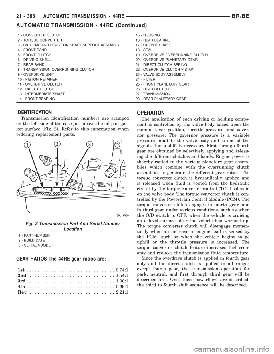
Transmission identification numbers are stamped
on the left side of the case just above the oil pan gas-
ket surface (Fig. 2). Refer to this information when
ordering replacement parts.
GEAR RATIOS The 44RE gear ratios are:
1st.................................2.74:1
2nd................................1.54:1
3rd.................................1.00:1
4th.................................0.69:1
Rev.................................2.21:1
OPERATION
The application of each driving or holding compo-
nent is controlled by the valve body based upon the
manual lever position, throttle pressure, and gover-
nor pressure. The governor pressure is a variable
pressure input to the valve body and is one of the
signals that a shift is necessary. First through fourth
gear are obtained by selectively applying and releas-
ing the different clutches and bands. Engine power is
thereby routed to the various planetary gear assem-
blies which combine with the overrunning clutch
assemblies to generate the different gear ratios. The
torque converter clutch is hydraulically applied and
is released when fluid is vented from the hydraulic
circuit by the torque converter control (TCC) solenoid
on the valve body. The torque converter clutch is con-
trolled by the Powertrain Control Module (PCM). The
torque converter clutch engages in fourth gear, and
in third gear under various conditions, such as when
the O/D switch is OFF, when the vehicle is cruising
on a level surface after the vehicle has warmed up.
The torque converter clutch will disengage momen-
tarily when an increase in engine load is sensed by
the PCM, such as when the vehicle begins to go
uphill or the throttle pressure is increased. The
torque converter clutch feature increases fuel econ-
omy and reduces the transmission fluid temperature.
Since the overdrive clutch is applied in fourth gear
only and the direct clutch is applied in all ranges
except fourth gear, the transmission operation for
park, neutral, and first through third gear will be
described first. Once these powerflows are described,
the third to fourth shift sequence will be described.
1 - CONVERTER CLUTCH 15 - HOUSING
2 - TORQUE CONVERTER 16 - REAR BEARING
3 - OIL PUMP AND REACTION SHAFT SUPPORT ASSEMBLY 17 - OUTPUT SHAFT
4 - FRONT BAND 18 - SEAL
5 - FRONT CLUTCH 19 - OVERDRIVE OVERRUNNING CLUTCH
6 - DRIVING SHELL 20 - OVERDRIVE PLANETARY GEAR
7 - REAR BAND 21 - DIRECT CLUTCH SPRING
8 - TRANSMISSION OVERRUNNING CLUTCH 22 - OVERDRIVE CLUTCH PISTON
9 - OVERDRIVE UNIT 23 - VALVE BODY ASSEMBLY
10 - PISTON RETAINER 24 - FILTER
11 - OVERDRIVE CLUTCH 25 - FRONT PLANETARY GEAR
12 - DIRECT CLUTCH 26 - REAR CLUTCH
13 - INTERMEDIATE SHAFT 27 - TRANSMISSION
14 - FRONT BEARING 28 - REAR PLANETARY GEAR
Fig. 2 Transmission Part And Serial Number
Location
1 - PART NUMBER
2 - BUILD DATE
3 - SERIAL NUMBER
21 - 308 AUTOMATIC TRANSMISSION - 44REBR/BE
AUTOMATIC TRANSMISSION - 44RE (Continued)