2001 DODGE RAM heater
[x] Cancel search: heaterPage 2679 of 2889
REMOVAL
WARNING: ON VEHICLES EQUIPPED WITH AIR-
BAGS, DISABLE THE AIRBAG SYSTEM BEFORE
ATTEMPTING ANY STEERING WHEEL, STEERING
COLUMN, OR INSTRUMENT PANEL COMPONENT
DIAGNOSIS OR SERVICE. DISCONNECT AND ISO-
LATE THE BATTERY NEGATIVE (GROUND) CABLE,
THEN WAIT TWO MINUTES FOR THE AIRBAG SYS-
TEM CAPACITOR TO DISCHARGE BEFORE PER-
FORMING FURTHER DIAGNOSIS OR SERVICE. THIS
IS THE ONLY SURE WAY TO DISABLE THE AIRBAG
SYSTEM. FAILURE TO TAKE THE PROPER PRE-
CAUTIONS COULD RESULT IN ACCIDENTAL AIR-
BAG DEPLOYMENT AND POSSIBLE PERSONAL
INJURY.
NOTE: Before starting this procedure, be certain to
turn the steering wheel until the front wheels are in
the straight-ahead position.
(1) Disconnect and isolate the battery negative
cable.
(2) Remove the Airbag Control Module (ACM) and
bracket from the floor panel transmission tunnel.
(Refer to 8 - ELECTRICAL/RESTRAINTS/AIRBAG
CONTROL MODULE - REMOVAL).
(3) Remove the trim from the left and right cowl
side inner panels. (Refer to 23 - BODY/INTERIOR/
COWL TRIM COVER - REMOVAL).
(4) Remove the steering column opening cover
from the instrument panel. (Refer to 23 - BODY/IN-
STRUMENT PANEL/STEERING COLUMN OPEN-
ING COVER - REMOVAL).
(5) Remove the two screws that secure the inside
hood latch release handle to the instrument panel
lower reinforcement and lower the release handle to
the floor.
(6) Disconnect the clockspring pigtail wire connec-
tor from the instrument panel wire harness connec-
tor located on the instrument panel lower
reinforcement.
(7) If the vehicle is so equipped, disconnect the
overdrive lockout switch pigtail wire connector from
the instrument panel wire harness connector near
the instrument panel lower reinforcement.
(8) Remove the steering column from the vehicle,
but do not remove the driver airbag, the steering
wheel, or the switches from the column. Be certain
that the steering wheel is locked and secured from
rotation to prevent the loss of clockspring centering.
(Refer to 19 - STEERING/COLUMN - REMOVAL).
(9) From under the driver side of the instrument
panel, perform the following:
(a) Disengage the park brake release handle
linkage rod from the park brake mechanism on theleft cowl side inner panel. (Refer to 5 - BRAKES/
PARKING BRAKE/RELEASE - REMOVAL).
(b) Disconnect the instrument panel wire har-
ness connector from the park brake switch on the
park brake mechanism.
(c) Disconnect the three connectors (one from the
body wire harness, and two from the headlamp and
dash wire harness) from the three connector recep-
tacles located closest to the dash panel on the back
of the Junction Block (JB).
(d) Remove the screw from the center of the
headlamp and dash wire harness to instrument
panel wire harness bulkhead connector and discon-
nect the connector.
(e) Disconnect the instrument panel wire har-
ness to door wire harness connector located directly
below the instrument panel wire harness to head-
lamp and dash wire harness bulkhead connector.
(f) If the vehicle is equipped with the Infinity
sound system option, disconnect the Infinity wire
harness connector from the instrument panel wire
harness connector that is secured to the outboard
side of the instrument panel wire harness to head-
lamp and dash wire harness bulkhead connector.
(g) Disconnect the instrument panel wire har-
ness connector from the stop lamp switch.
(h) Disconnect the heater-A/C housing vacuum
harness connector from the heater-A/C control vac-
uum harness connector located near the left end of
the heater-A/C housing.
(10) From under the passenger side of the instru-
ment panel, disconnect the two halves of the radio
antenna coaxial cable connector.
(11) Loosen the right and left instrument panel
cowl side roll-down bracket screws about 13 mm
(0.50 inch) (Fig. 1).
(12) Remove the five screws that secure the top of
the instrument panel to the top of the dash panel,
removing the center screw last.
(13) Roll down the instrument panel and install a
temporary hook in the center hole on top of the
instrument panel. Secure the other end of the hook
to the center hole in the top of the dash panel. The
hook should support the instrument panel in its
rolled down position about 46 cm (18 inches) from
the dash panel.
(14) With the instrument panel supported in the
roll-down position, disconnect the instrument panel
wire harness connectors from the heater-A/C housing
wire harness connectors.
(15) With the aid of an assistant, remove the tem-
porary hook and lift the instrument panel assembly
off of the roll-down bracket screws and remove it
from the vehicle.
23 - 106 INSTRUMENT PANEL SYSTEMBR/BE
INSTRUMENT PANEL SYSTEM (Continued)
Page 2680 of 2889
INSTALLATION
WARNING: ON VEHICLES EQUIPPED WITH AIR-
BAGS, DISABLE THE AIRBAG SYSTEM BEFORE
ATTEMPTING ANY STEERING WHEEL, STEERING
COLUMN, OR INSTRUMENT PANEL COMPONENT
DIAGNOSIS OR SERVICE. DISCONNECT AND ISO-
LATE THE BATTERY NEGATIVE (GROUND) CABLE,
THEN WAIT TWO MINUTES FOR THE AIRBAG SYS-
TEM CAPACITOR TO DISCHARGE BEFORE PER-
FORMING FURTHER DIAGNOSIS OR SERVICE. THIS
IS THE ONLY SURE WAY TO DISABLE THE AIRBAG
SYSTEM. FAILURE TO TAKE THE PROPER PRE-
CAUTIONS COULD RESULT IN ACCIDENTAL AIR-
BAG DEPLOYMENT AND POSSIBLE PERSONAL
INJURY.
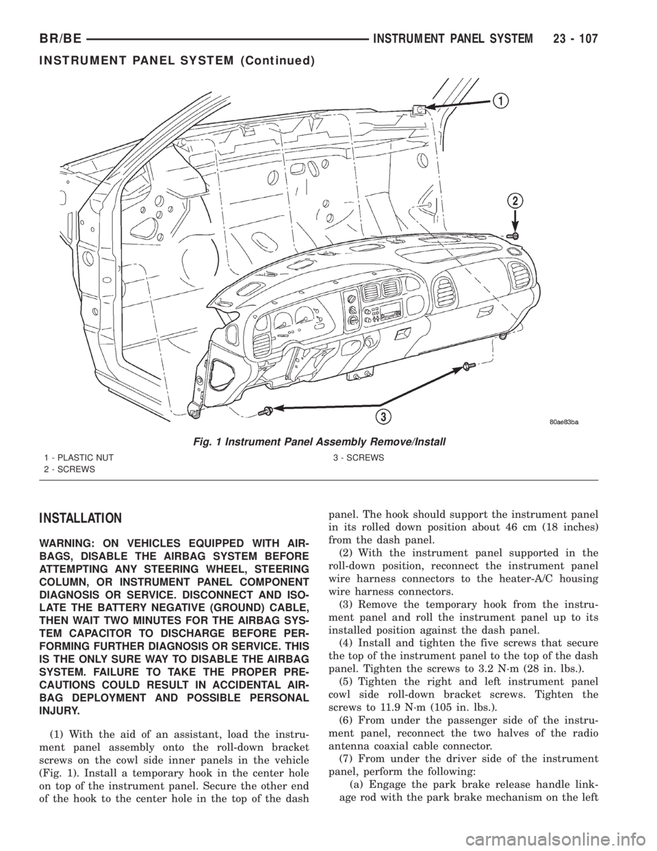
(1) With the aid of an assistant, load the instru-
ment panel assembly onto the roll-down bracket
screws on the cowl side inner panels in the vehicle
(Fig. 1). Install a temporary hook in the center hole
on top of the instrument panel. Secure the other end
of the hook to the center hole in the top of the dashpanel. The hook should support the instrument panel
in its rolled down position about 46 cm (18 inches)
from the dash panel.
(2) With the instrument panel supported in the
roll-down position, reconnect the instrument panel
wire harness connectors to the heater-A/C housing
wire harness connectors.
(3) Remove the temporary hook from the instru-
ment panel and roll the instrument panel up to its
installed position against the dash panel.
(4) Install and tighten the five screws that secure
the top of the instrument panel to the top of the dash
panel. Tighten the screws to 3.2 N´m (28 in. lbs.).
(5) Tighten the right and left instrument panel
cowl side roll-down bracket screws. Tighten the
screws to 11.9 N´m (105 in. lbs.).
(6) From under the passenger side of the instru-
ment panel, reconnect the two halves of the radio
antenna coaxial cable connector.
(7) From under the driver side of the instrument
panel, perform the following:
(a) Engage the park brake release handle link-
age rod with the park brake mechanism on the left
Fig. 1 Instrument Panel Assembly Remove/Install
1 - PLASTIC NUT
2 - SCREWS3 - SCREWS
BR/BEINSTRUMENT PANEL SYSTEM 23 - 107
INSTRUMENT PANEL SYSTEM (Continued)
Page 2681 of 2889
cowl side inner panel. (Refer to 5 - BRAKES/PARK-
ING BRAKE/RELEASE - INSTALLATION).
(b) Reconnect the instrument panel wire harness
connector to the park brake switch on the park
brake mechanism.
(c) Reconnect the three connectors (one from the
body wire harness, and two from the headlamp and
dash wire harness) to the three connector recepta-
cles located closest to the dash panel on the back of
the Junction Block (JB).
(d) Reconnect the headlamp and dash wire har-
ness to instrument panel wire harness bulkhead
connector and tighten the screw in the center of
the connector. Tighten the screw to 3.5 N´m (31 in.
lbs.).
(e) Reconnect the instrument panel wire harness
to door wire harness connector located directly
below the instrument panel wire harness to head-
lamp and dash wire harness bulkhead connector.
(f) If the vehicle is equipped with the Infinity
sound system option, reconnect the Infinity wire
harness connector to the instrument panel wire
harness connector that is secured to the outboard
side of the instrument panel wire harness to head-
lamp and dash wire harness bulkhead connector.
(g) Reconnect the instrument panel wire harness
connector to the stop lamp switch.
(h) Reconnect the heater-A/C housing vacuum
harness connector to the heater-A/C control vac-
uum harness connector located near the left end of
the heater-A/C housing.
(8) Reinstall the steering column into the vehicle.
Be certain that the steering wheel was locked and
secured from rotation to prevent the loss of clock-
spring centering. (Refer to 19 - STEERING/COL-
UMN - INSTALLATION).
(9) If the vehicle is so equipped, reconnect the
overdrive lockout switch pigtail wire connector to the
instrument panel wire harness connector near the
instrument panel lower reinforcement.
(10) Reconnect the clockspring pigtail wire connec-
tor to the instrument panel wire harness connector
at the instrument panel lower reinforcement.
(11) Position the inside hood latch release handle
to the instrument panel lower reinforcement.
(12) Install and tighten the two screws that secure
the inside hood latch release handle to the instru-
ment panel lower reinforcement. Tighten the screws
to 2.8 N´m (25 in. lbs.).
(13) Reinstall the steering column opening cover
onto the instrument panel. (Refer to 23 - BODY/IN-
STRUMENT PANEL/STEERING COLUMN OPEN-
ING COVER - INSTALLATION).
(14) Reinstall the trim onto the left and right cowl
side inner panels. (Refer to 23 - BODY/INTERIOR/
COWL TRIM COVER - INSTALLATION).(15) Reinstall the Airbag Control Module (ACM)
and bracket onto the floor panel transmission tunnel.
(Refer to 8 - ELECTRICAL/RESTRAINTS/AIRBAG
CONTROL MODULE - INSTALLATION).
(16) Reconnect the battery negative cable.
ASH RECEIVER
REMOVAL
WARNING: ON VEHICLES EQUIPPED WITH AIR-
BAGS, DISABLE THE AIRBAG SYSTEM BEFORE
ATTEMPTING ANY STEERING WHEEL, STEERING
COLUMN, OR INSTRUMENT PANEL COMPONENT
DIAGNOSIS OR SERVICE. DISCONNECT AND ISO-
LATE THE BATTERY NEGATIVE (GROUND) CABLE,
THEN WAIT TWO MINUTES FOR THE AIRBAG SYS-
TEM CAPACITOR TO DISCHARGE BEFORE PER-
FORMING FURTHER DIAGNOSIS OR SERVICE. THIS
IS THE ONLY SURE WAY TO DISABLE THE AIRBAG
SYSTEM. FAILURE TO TAKE THE PROPER PRE-
CAUTIONS COULD RESULT IN ACCIDENTAL AIR-
BAG DEPLOYMENT AND POSSIBLE PERSONAL
INJURY.
(1) Disconnect and isolate the battery negative
cable.
(2) Open the instrument panel ash receiver.
(3) From the open position, close the ash receiver
slightly and pull it straight back far enough to disen-
gage it from the pivot pins in the lower instrument
panel.
(4) Remove the three screws that secure the ash
receiver flame shield to the lower instrument panel
(Fig. 2).
(5) Pull the ash receiver flame shield out from the
instrument panel far enough to disengage the two
retaining tabs on the top of the shield from the
mounting holes in the instrument panel.
(6) Lower the flame shield from the instrument
panel far enough to access the ash receiver lamp and
hood.
(7) Squeeze the ash receiver lamp and hood
bracket to disengage the unit from the mounting hole
in the flame shield.
(8) Remove the ash receiver flame shield from the
instrument panel.
23 - 108 INSTRUMENT PANEL SYSTEMBR/BE
INSTRUMENT PANEL SYSTEM (Continued)
Page 2730 of 2889
HEATING & AIR CONDITIONING
TABLE OF CONTENTS
page page
HEATING & AIR CONDITIONING
DESCRIPTION............................1
OPERATION.............................1
DIAGNOSIS AND TESTING..................2
A/C PERFORMANCE.....................2
HEATER PERFORMANCE.................6STANDARD PROCEDURE...................7
DIODE REPLACEMENT...................7
SPECIFICATIONS.........................8
CONTROLS..............................9
DISTRIBUTION..........................31
PLUMBING.............................40
HEATING & AIR
CONDITIONING
DESCRIPTION - HEATER AND AIR
CONDITIONER
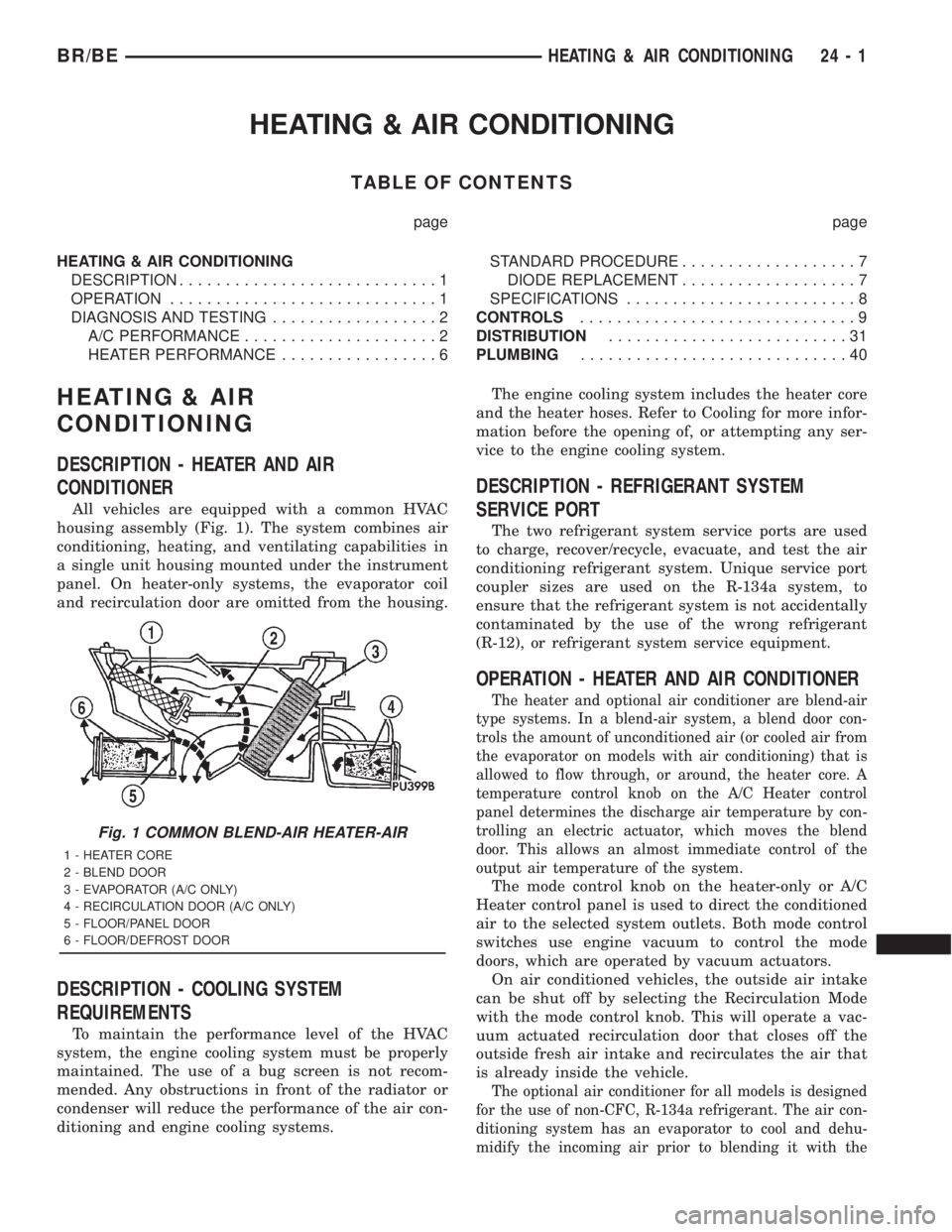
All vehicles are equipped with a common HVAC
housing assembly (Fig. 1). The system combines air
conditioning, heating, and ventilating capabilities in
a single unit housing mounted under the instrument
panel. On heater-only systems, the evaporator coil
and recirculation door are omitted from the housing.
DESCRIPTION - COOLING SYSTEM
REQUIREMENTS
To maintain the performance level of the HVAC
system, the engine cooling system must be properly
maintained. The use of a bug screen is not recom-
mended. Any obstructions in front of the radiator or
condenser will reduce the performance of the air con-
ditioning and engine cooling systems.The engine cooling system includes the heater core
and the heater hoses. Refer to Cooling for more infor-
mation before the opening of, or attempting any ser-
vice to the engine cooling system.
DESCRIPTION - REFRIGERANT SYSTEM
SERVICE PORT
The two refrigerant system service ports are used
to charge, recover/recycle, evacuate, and test the air
conditioning refrigerant system. Unique service port
coupler sizes are used on the R-134a system, to
ensure that the refrigerant system is not accidentally
contaminated by the use of the wrong refrigerant
(R-12), or refrigerant system service equipment.
OPERATION - HEATER AND AIR CONDITIONER
The heater and optional air conditioner are blend-air
type systems. In a blend-air system, a blend door con-
trols the amount of unconditioned air (or cooled air from
the evaporator on models with air conditioning) that is
allowed to flow through, or around, the heater core. A
temperature control knob on the A/C Heater control
panel determines the discharge air temperature by con-
trolling an electric actuator, which moves the blend
door. This allows an almost immediate control of the
output air temperature of the system.
The mode control knob on the heater-only or A/C
Heater control panel is used to direct the conditioned
air to the selected system outlets. Both mode control
switches use engine vacuum to control the mode
doors, which are operated by vacuum actuators.
On air conditioned vehicles, the outside air intake
can be shut off by selecting the Recirculation Mode
with the mode control knob. This will operate a vac-
uum actuated recirculation door that closes off the
outside fresh air intake and recirculates the air that
is already inside the vehicle.
The optional air conditioner for all models is designed
for the use of non-CFC, R-134a refrigerant. The air con-
ditioning system has an evaporator to cool and dehu-
midify the incoming air prior to blending it with the
Fig. 1 COMMON BLEND-AIR HEATER-AIR
1 - HEATER CORE
2 - BLEND DOOR
3 - EVAPORATOR (A/C ONLY)
4 - RECIRCULATION DOOR (A/C ONLY)
5 - FLOOR/PANEL DOOR
6 - FLOOR/DEFROST DOOR
BR/BEHEATING & AIR CONDITIONING 24 - 1
Page 2731 of 2889
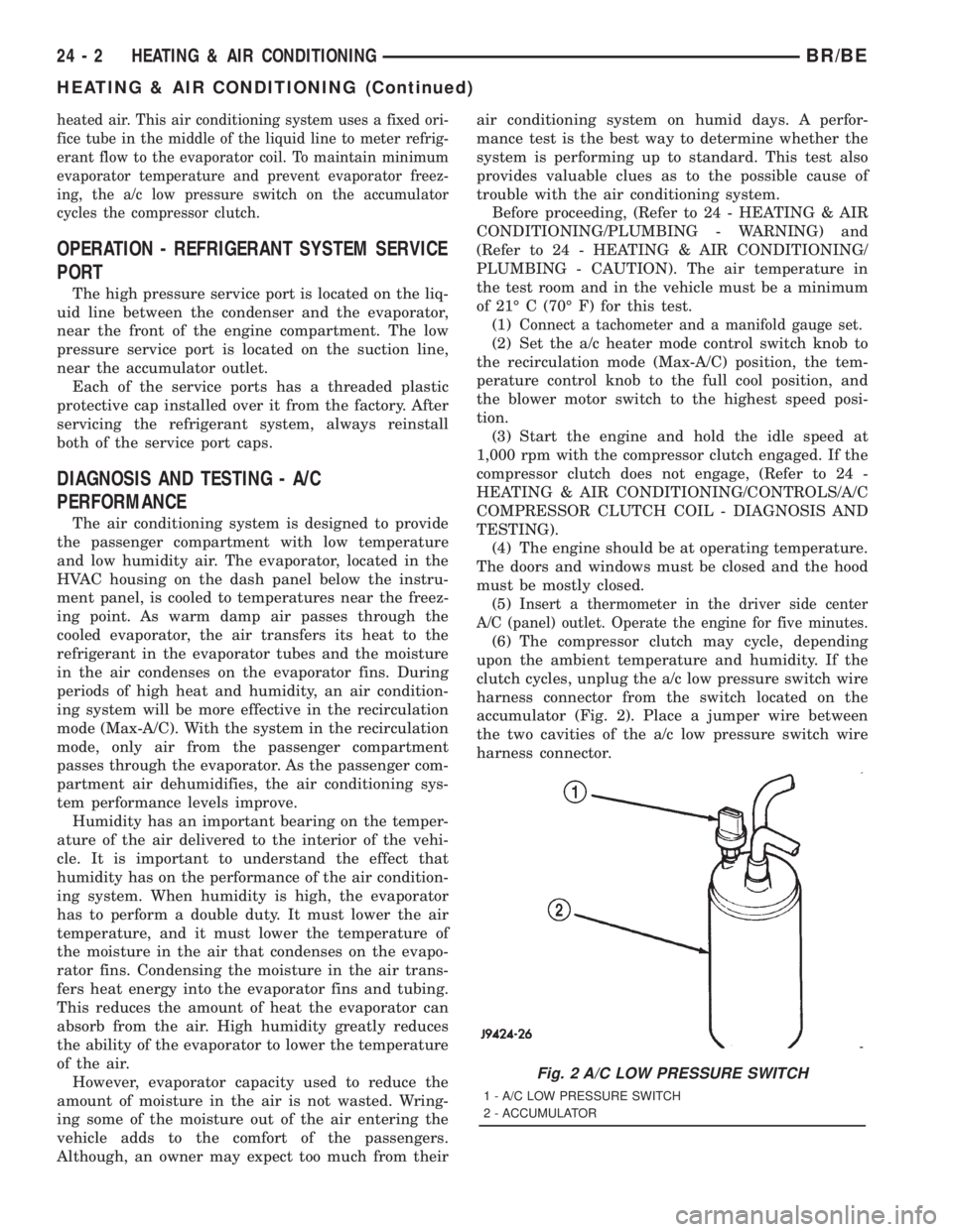
heated air. This air conditioning system uses a fixed ori-
fice tube in the middle of the liquid line to meter refrig-
erant flow to the evaporator coil. To maintain minimum
evaporator temperature and prevent evaporator freez-
ing, the a/c low pressure switch on the accumulator
cycles the compressor clutch.
OPERATION - REFRIGERANT SYSTEM SERVICE
PORT
The high pressure service port is located on the liq-
uid line between the condenser and the evaporator,
near the front of the engine compartment. The low
pressure service port is located on the suction line,
near the accumulator outlet.
Each of the service ports has a threaded plastic
protective cap installed over it from the factory. After
servicing the refrigerant system, always reinstall
both of the service port caps.
DIAGNOSIS AND TESTING - A/C
PERFORMANCE
The air conditioning system is designed to provide
the passenger compartment with low temperature
and low humidity air. The evaporator, located in the
HVAC housing on the dash panel below the instru-
ment panel, is cooled to temperatures near the freez-
ing point. As warm damp air passes through the
cooled evaporator, the air transfers its heat to the
refrigerant in the evaporator tubes and the moisture
in the air condenses on the evaporator fins. During
periods of high heat and humidity, an air condition-
ing system will be more effective in the recirculation
mode (Max-A/C). With the system in the recirculation
mode, only air from the passenger compartment
passes through the evaporator. As the passenger com-
partment air dehumidifies, the air conditioning sys-
tem performance levels improve.
Humidity has an important bearing on the temper-
ature of the air delivered to the interior of the vehi-
cle. It is important to understand the effect that
humidity has on the performance of the air condition-
ing system. When humidity is high, the evaporator
has to perform a double duty. It must lower the air
temperature, and it must lower the temperature of
the moisture in the air that condenses on the evapo-
rator fins. Condensing the moisture in the air trans-
fers heat energy into the evaporator fins and tubing.
This reduces the amount of heat the evaporator can
absorb from the air. High humidity greatly reduces
the ability of the evaporator to lower the temperature
of the air.
However, evaporator capacity used to reduce the
amount of moisture in the air is not wasted. Wring-
ing some of the moisture out of the air entering the
vehicle adds to the comfort of the passengers.
Although, an owner may expect too much from theirair conditioning system on humid days. A perfor-
mance test is the best way to determine whether the
system is performing up to standard. This test also
provides valuable clues as to the possible cause of
trouble with the air conditioning system.
Before proceeding, (Refer to 24 - HEATING & AIR
CONDITIONING/PLUMBING - WARNING) and
(Refer to 24 - HEATING & AIR CONDITIONING/
PLUMBING - CAUTION). The air temperature in
the test room and in the vehicle must be a minimum
of 21É C (70É F) for this test.
(1)
Connect a tachometer and a manifold gauge set.
(2) Set the a/c heater mode control switch knob to
the recirculation mode (Max-A/C) position, the tem-
perature control knob to the full cool position, and
the blower motor switch to the highest speed posi-
tion.
(3) Start the engine and hold the idle speed at
1,000 rpm with the compressor clutch engaged. If the
compressor clutch does not engage, (Refer to 24 -
HEATING & AIR CONDITIONING/CONTROLS/A/C
COMPRESSOR CLUTCH COIL - DIAGNOSIS AND
TESTING).
(4) The engine should be at operating temperature.
The doors and windows must be closed and the hood
must be mostly closed.
(5)
Insert a thermometer in the driver side center
A/C (panel) outlet. Operate the engine for five minutes.
(6) The compressor clutch may cycle, depending
upon the ambient temperature and humidity. If the
clutch cycles, unplug the a/c low pressure switch wire
harness connector from the switch located on the
accumulator (Fig. 2). Place a jumper wire between
the two cavities of the a/c low pressure switch wire
harness connector.
Fig. 2 A/C LOW PRESSURE SWITCH
1 - A/C LOW PRESSURE SWITCH
2 - ACCUMULATOR
24 - 2 HEATING & AIR CONDITIONINGBR/BE
HEATING & AIR CONDITIONING (Continued)
Page 2732 of 2889
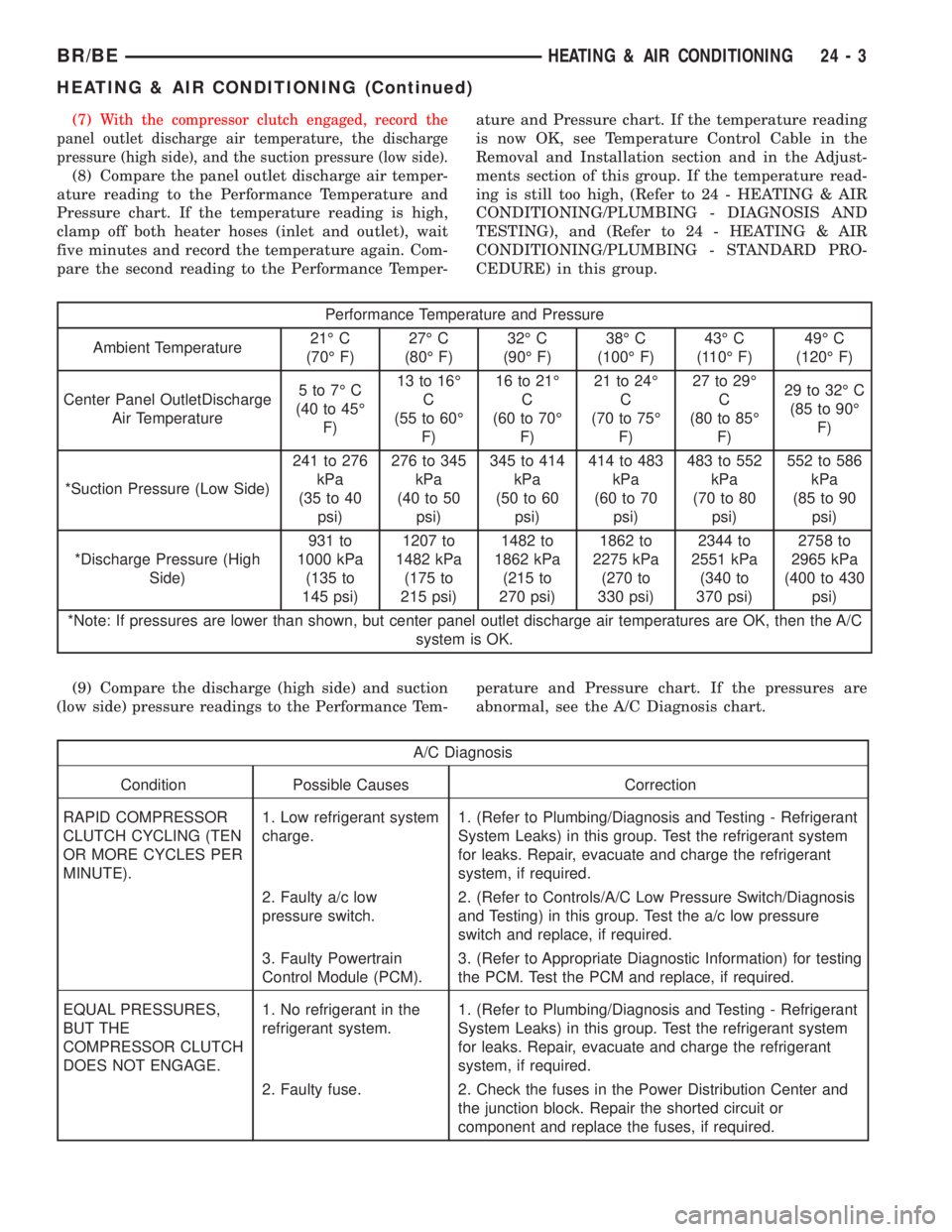
(7)With the compressor clutch engaged, record the
panel outlet discharge air temperature, the discharge
pressure (high side), and the suction pressure (low side).
(8) Compare the panel outlet discharge air temper-
ature reading to the Performance Temperature and
Pressure chart. If the temperature reading is high,
clamp off both heater hoses (inlet and outlet), wait
five minutes and record the temperature again. Com-
pare the second reading to the Performance Temper-ature and Pressure chart. If the temperature reading
is now OK, see Temperature Control Cable in the
Removal and Installation section and in the Adjust-
ments section of this group. If the temperature read-
ing is still too high, (Refer to 24 - HEATING & AIR
CONDITIONING/PLUMBING - DIAGNOSIS AND
TESTING), and (Refer to 24 - HEATING & AIR
CONDITIONING/PLUMBING - STANDARD PRO-
CEDURE) in this group.
Performance Temperature and Pressure
Ambient Temperature21É C
(70É F)27É C
(80É F)32É C
(90É F)38É C
(100É F)43É C
(110É F)49É C
(120É F)
Center Panel OutletDischarge
Air Temperature5to7ÉC
(40 to 45É
F)13 to 16É
C
(55 to 60É
F)16 to 21É
C
(60 to 70É
F)21 to 24É
C
(70 to 75É
F)27 to 29É
C
(80 to 85É
F)29 to 32É C
(85 to 90É
F)
*Suction Pressure (Low Side)241 to 276
kPa
(35 to 40
psi)276 to 345
kPa
(40 to 50
psi)345 to 414
kPa
(50 to 60
psi)414 to 483
kPa
(60 to 70
psi)483 to 552
kPa
(70 to 80
psi)552 to 586
kPa
(85 to 90
psi)
*Discharge Pressure (High
Side)931 to
1000 kPa
(135 to
145 psi)1207 to
1482 kPa
(175 to
215 psi)1482 to
1862 kPa
(215 to
270 psi)1862 to
2275 kPa
(270 to
330 psi)2344 to
2551 kPa
(340 to
370 psi)2758 to
2965 kPa
(400 to 430
psi)
*Note: If pressures are lower than shown, but center panel outlet discharge air temperatures are OK, then the A/C
system is OK.
(9) Compare the discharge (high side) and suction
(low side) pressure readings to the Performance Tem-perature and Pressure chart. If the pressures are
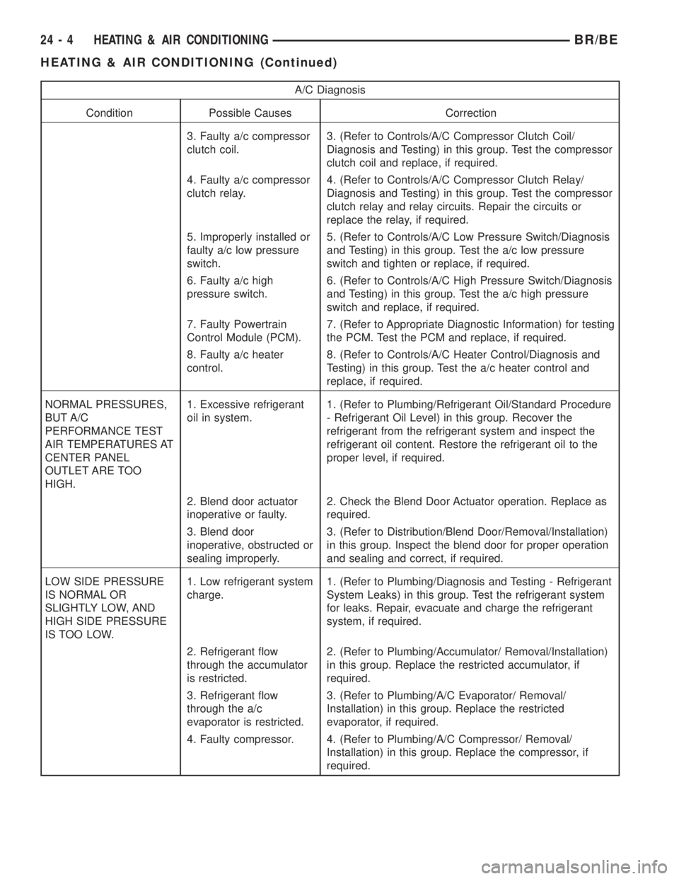
abnormal, see the A/C Diagnosis chart.
A/C Diagnosis
Condition Possible Causes Correction
RAPID COMPRESSOR
CLUTCH CYCLING (TEN
OR MORE CYCLES PER
MINUTE).1. Low refrigerant system
charge.1. (Refer to Plumbing/Diagnosis and Testing - Refrigerant
System Leaks) in this group. Test the refrigerant system
for leaks. Repair, evacuate and charge the refrigerant
system, if required.
2. Faulty a/c low
pressure switch.2. (Refer to Controls/A/C Low Pressure Switch/Diagnosis
and Testing) in this group. Test the a/c low pressure
switch and replace, if required.
3. Faulty Powertrain
Control Module (PCM).3. (Refer to Appropriate Diagnostic Information) for testing
the PCM. Test the PCM and replace, if required.
EQUAL PRESSURES,
BUT THE
COMPRESSOR CLUTCH
DOES NOT ENGAGE.1. No refrigerant in the
refrigerant system.1. (Refer to Plumbing/Diagnosis and Testing - Refrigerant
System Leaks) in this group. Test the refrigerant system
for leaks. Repair, evacuate and charge the refrigerant
system, if required.
2. Faulty fuse. 2. Check the fuses in the Power Distribution Center and
the junction block. Repair the shorted circuit or
component and replace the fuses, if required.
BR/BEHEATING & AIR CONDITIONING 24 - 3
HEATING & AIR CONDITIONING (Continued)
Page 2733 of 2889
A/C Diagnosis
Condition Possible Causes Correction
3. Faulty a/c compressor
clutch coil.3. (Refer to Controls/A/C Compressor Clutch Coil/
Diagnosis and Testing) in this group. Test the compressor
clutch coil and replace, if required.
4. Faulty a/c compressor
clutch relay.4. (Refer to Controls/A/C Compressor Clutch Relay/
Diagnosis and Testing) in this group. Test the compressor
clutch relay and relay circuits. Repair the circuits or
replace the relay, if required.
5. Improperly installed or
faulty a/c low pressure
switch.5. (Refer to Controls/A/C Low Pressure Switch/Diagnosis
and Testing) in this group. Test the a/c low pressure
switch and tighten or replace, if required.
6. Faulty a/c high
pressure switch.6. (Refer to Controls/A/C High Pressure Switch/Diagnosis
and Testing) in this group. Test the a/c high pressure
switch and replace, if required.
7. Faulty Powertrain
Control Module (PCM).7. (Refer to Appropriate Diagnostic Information) for testing
the PCM. Test the PCM and replace, if required.
8. Faulty a/c heater
control.8. (Refer to Controls/A/C Heater Control/Diagnosis and
Testing) in this group. Test the a/c heater control and
replace, if required.
NORMAL PRESSURES,
BUT A/C
PERFORMANCE TEST
AIR TEMPERATURES AT
CENTER PANEL
OUTLET ARE TOO
HIGH.1. Excessive refrigerant
oil in system.1. (Refer to Plumbing/Refrigerant Oil/Standard Procedure
- Refrigerant Oil Level) in this group. Recover the
refrigerant from the refrigerant system and inspect the
refrigerant oil content. Restore the refrigerant oil to the
proper level, if required.
2. Blend door actuator
inoperative or faulty.2. Check the Blend Door Actuator operation. Replace as
required.
3. Blend door
inoperative, obstructed or
sealing improperly.3. (Refer to Distribution/Blend Door/Removal/Installation)
in this group. Inspect the blend door for proper operation
and sealing and correct, if required.
LOW SIDE PRESSURE
IS NORMAL OR
SLIGHTLY LOW, AND
HIGH SIDE PRESSURE
IS TOO LOW.1. Low refrigerant system
charge.1. (Refer to Plumbing/Diagnosis and Testing - Refrigerant
System Leaks) in this group. Test the refrigerant system
for leaks. Repair, evacuate and charge the refrigerant
system, if required.
2. Refrigerant flow
through the accumulator
is restricted.2. (Refer to Plumbing/Accumulator/ Removal/Installation)
in this group. Replace the restricted accumulator, if
required.
3. Refrigerant flow
through the a/c
evaporator is restricted.3. (Refer to Plumbing/A/C Evaporator/ Removal/
Installation) in this group. Replace the restricted
evaporator, if required.
4. Faulty compressor. 4. (Refer to Plumbing/A/C Compressor/ Removal/
Installation) in this group. Replace the compressor, if
required.
24 - 4 HEATING & AIR CONDITIONINGBR/BE
HEATING & AIR CONDITIONING (Continued)
Page 2735 of 2889
DIAGNOSIS AND TESTING - HEATER
PERFORMANCE
Before performing the following tests, refer to Cool-
ing for the procedures to check the engine coolant
level and flow, engine coolant reserve/recovery sys-
tem operation, accessory drive belt condition and ten-
sion, radiator air flow and the fan drive operation.
Also be certain that the accessory vacuum supply
line is connected at the engine vacuum source.
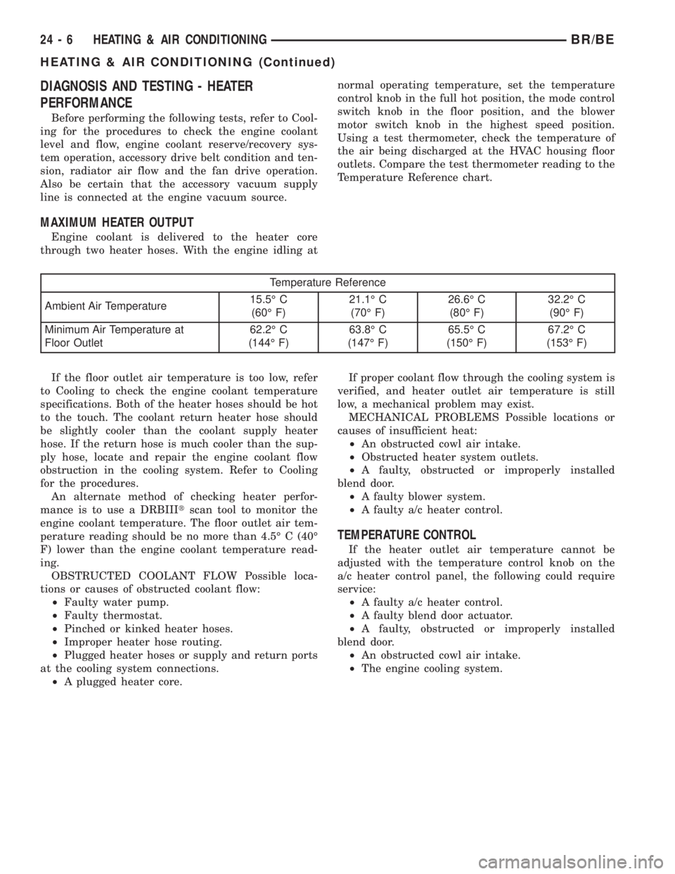
MAXIMUM HEATER OUTPUT
Engine coolant is delivered to the heater core
through two heater hoses. With the engine idling atnormal operating temperature, set the temperature
control knob in the full hot position, the mode control
switch knob in the floor position, and the blower
motor switch knob in the highest speed position.
Using a test thermometer, check the temperature of
the air being discharged at the HVAC housing floor
outlets. Compare the test thermometer reading to the
Temperature Reference chart.
Temperature Reference
Ambient Air Temperature15.5É C
(60É F)21.1É C
(70É F)26.6É C
(80É F)32.2É C
(90É F)
Minimum Air Temperature at
Floor Outlet62.2É C
(144É F)63.8É C
(147É F)65.5É C
(150É F)67.2É C
(153É F)
If the floor outlet air temperature is too low, refer
to Cooling to check the engine coolant temperature
specifications. Both of the heater hoses should be hot
to the touch. The coolant return heater hose should
be slightly cooler than the coolant supply heater
hose. If the return hose is much cooler than the sup-
ply hose, locate and repair the engine coolant flow
obstruction in the cooling system. Refer to Cooling
for the procedures.
An alternate method of checking heater perfor-
mance is to use a DRBIIItscan tool to monitor the
engine coolant temperature. The floor outlet air tem-
perature reading should be no more than 4.5É C (40É
F) lower than the engine coolant temperature read-
ing.
OBSTRUCTED COOLANT FLOW Possible loca-
tions or causes of obstructed coolant flow:
²Faulty water pump.
²Faulty thermostat.
²Pinched or kinked heater hoses.
²Improper heater hose routing.
²Plugged heater hoses or supply and return ports
at the cooling system connections.
²A plugged heater core.If proper coolant flow through the cooling system is
verified, and heater outlet air temperature is still
low, a mechanical problem may exist.
MECHANICAL PROBLEMS Possible locations or
causes of insufficient heat:
²An obstructed cowl air intake.
²Obstructed heater system outlets.
²A faulty, obstructed or improperly installed
blend door.
²A faulty blower system.
²A faulty a/c heater control.
TEMPERATURE CONTROL
If the heater outlet air temperature cannot be
adjusted with the temperature control knob on the
a/c heater control panel, the following could require
service:
²A faulty a/c heater control.
²A faulty blend door actuator.
²A faulty, obstructed or improperly installed
blend door.
²An obstructed cowl air intake.
²The engine cooling system.
24 - 6 HEATING & AIR CONDITIONINGBR/BE
HEATING & AIR CONDITIONING (Continued)