2001 DODGE RAM heater
[x] Cancel search: heaterPage 1450 of 2889
(5) Using two (2) new gaskets, install the intake
air grid heater and air inlet housing (Fig. 168). Posi-
tion the ground cable and install and tighten the
bolts to 24 N´m (18 ft. lbs.) torque.
(6) Install and tighten the air intake heater power
supply nuts to 14 N´m (120 in. lbs.) torque.
(7) Install the engine oil dipstick tube and mount-
ing bolt (Fig. 167).
(8) Position the charge air cooler outlet tube onto
the air inlet housing (Fig. 167). Tighten the clamps
to 8 N´m (72 in. lbs.) torque.
(9) Perform the fuel system air bleed procedure
(Refer to 14 - FUEL SYSTEM/FUEL DELIVERY -
STANDARD PROCEDURE).
(10) Connect the battery negative cables.
EXHAUST MANIFOLD
REMOVAL
(1) Disconnect the battery negative cables.
(2) Raise vehicle on hoist.
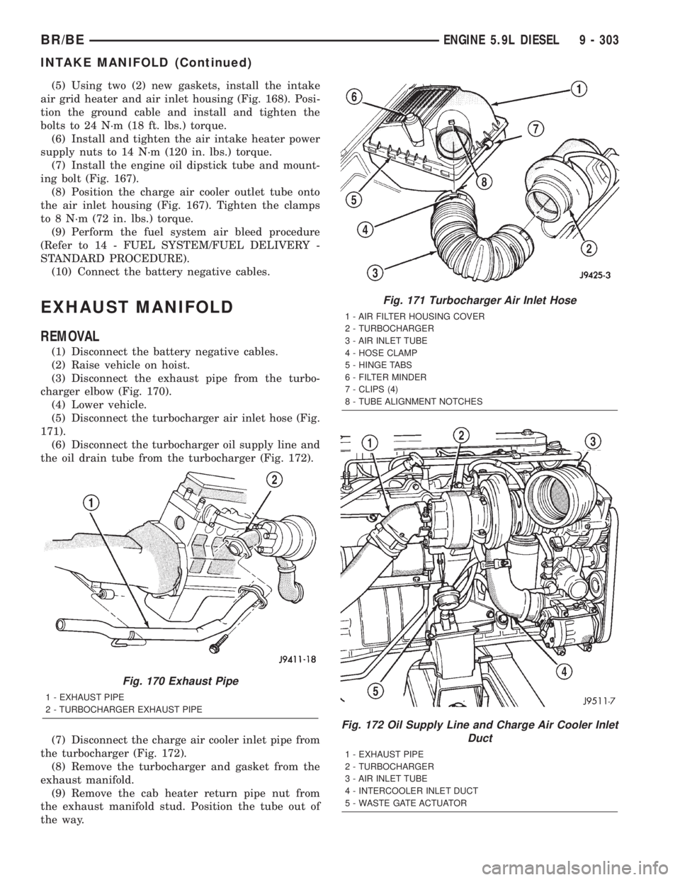
(3) Disconnect the exhaust pipe from the turbo-
charger elbow (Fig. 170).
(4) Lower vehicle.
(5) Disconnect the turbocharger air inlet hose (Fig.
171).
(6) Disconnect the turbocharger oil supply line and
the oil drain tube from the turbocharger (Fig. 172).
(7) Disconnect the charge air cooler inlet pipe from
the turbocharger (Fig. 172).
(8) Remove the turbocharger and gasket from the
exhaust manifold.
(9) Remove the cab heater return pipe nut from
the exhaust manifold stud. Position the tube out of
the way.
Fig. 170 Exhaust Pipe
1 - EXHAUST PIPE
2 - TURBOCHARGER EXHAUST PIPE
Fig. 171 Turbocharger Air Inlet Hose
1 - AIR FILTER HOUSING COVER
2 - TURBOCHARGER
3 - AIR INLET TUBE
4 - HOSE CLAMP
5 - HINGE TABS
6 - FILTER MINDER
7 - CLIPS (4)
8 - TUBE ALIGNMENT NOTCHES
Fig. 172 Oil Supply Line and Charge Air Cooler Inlet
Duct
1 - EXHAUST PIPE
2 - TURBOCHARGER
3 - AIR INLET TUBE
4 - INTERCOOLER INLET DUCT
5 - WASTE GATE ACTUATOR
BR/BEENGINE 5.9L DIESEL 9 - 303
INTAKE MANIFOLD (Continued)
Page 1451 of 2889
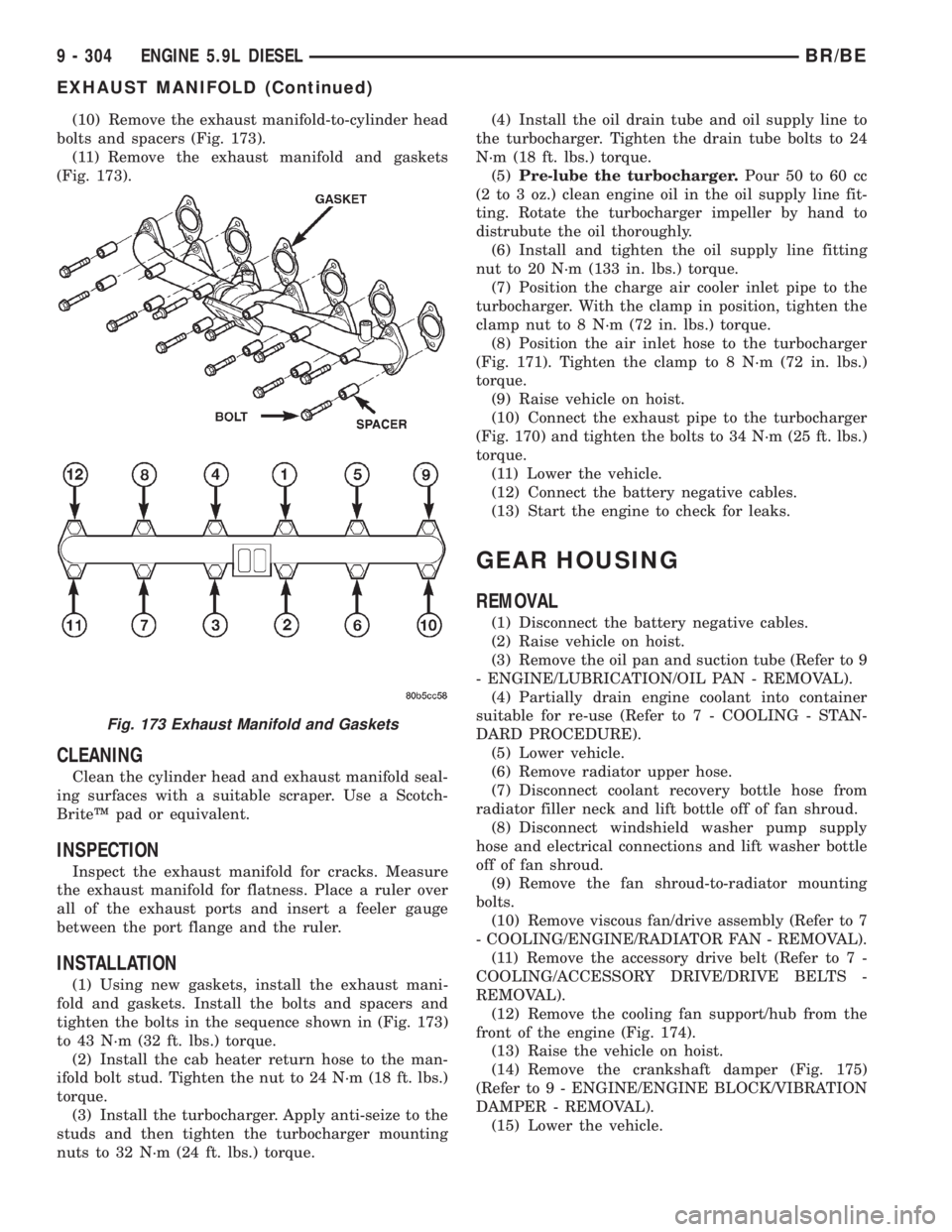
(10) Remove the exhaust manifold-to-cylinder head
bolts and spacers (Fig. 173).
(11) Remove the exhaust manifold and gaskets
(Fig. 173).
CLEANING
Clean the cylinder head and exhaust manifold seal-
ing surfaces with a suitable scraper. Use a Scotch-
BriteŸ pad or equivalent.
INSPECTION
Inspect the exhaust manifold for cracks. Measure
the exhaust manifold for flatness. Place a ruler over
all of the exhaust ports and insert a feeler gauge
between the port flange and the ruler.
INSTALLATION
(1) Using new gaskets, install the exhaust mani-
fold and gaskets. Install the bolts and spacers and
tighten the bolts in the sequence shown in (Fig. 173)
to 43 N´m (32 ft. lbs.) torque.
(2) Install the cab heater return hose to the man-
ifold bolt stud. Tighten the nut to 24 N´m (18 ft. lbs.)
torque.
(3) Install the turbocharger. Apply anti-seize to the
studs and then tighten the turbocharger mounting
nuts to 32 N´m (24 ft. lbs.) torque.(4) Install the oil drain tube and oil supply line to
the turbocharger. Tighten the drain tube bolts to 24
N´m (18 ft. lbs.) torque.
(5)Pre-lube the turbocharger.Pour 50 to 60 cc
(2 to 3 oz.) clean engine oil in the oil supply line fit-
ting. Rotate the turbocharger impeller by hand to
distrubute the oil thoroughly.
(6) Install and tighten the oil supply line fitting
nut to 20 N´m (133 in. lbs.) torque.
(7) Position the charge air cooler inlet pipe to the
turbocharger. With the clamp in position, tighten the
clamp nut to 8 N´m (72 in. lbs.) torque.
(8) Position the air inlet hose to the turbocharger
(Fig. 171). Tighten the clamp to 8 N´m (72 in. lbs.)
torque.
(9) Raise vehicle on hoist.
(10) Connect the exhaust pipe to the turbocharger
(Fig. 170) and tighten the bolts to 34 N´m (25 ft. lbs.)
torque.
(11) Lower the vehicle.
(12) Connect the battery negative cables.
(13) Start the engine to check for leaks.
GEAR HOUSING
REMOVAL
(1) Disconnect the battery negative cables.
(2) Raise vehicle on hoist.
(3) Remove the oil pan and suction tube (Refer to 9
- ENGINE/LUBRICATION/OIL PAN - REMOVAL).
(4) Partially drain engine coolant into container
suitable for re-use (Refer to 7 - COOLING - STAN-
DARD PROCEDURE).
(5) Lower vehicle.
(6) Remove radiator upper hose.
(7) Disconnect coolant recovery bottle hose from
radiator filler neck and lift bottle off of fan shroud.
(8) Disconnect windshield washer pump supply
hose and electrical connections and lift washer bottle
off of fan shroud.
(9) Remove the fan shroud-to-radiator mounting
bolts.
(10) Remove viscous fan/drive assembly (Refer to 7
- COOLING/ENGINE/RADIATOR FAN - REMOVAL).
(11) Remove the accessory drive belt (Refer to 7 -
COOLING/ACCESSORY DRIVE/DRIVE BELTS -
REMOVAL).
(12) Remove the cooling fan support/hub from the
front of the engine (Fig. 174).
(13) Raise the vehicle on hoist.
(14) Remove the crankshaft damper (Fig. 175)
(Refer to 9 - ENGINE/ENGINE BLOCK/VIBRATION
DAMPER - REMOVAL).
(15) Lower the vehicle.
Fig. 173 Exhaust Manifold and Gaskets
9 - 304 ENGINE 5.9L DIESELBR/BE
EXHAUST MANIFOLD (Continued)
Page 1460 of 2889
SPECIFICATIONS
TORQUE
DESCRIPTION N´m Ft. In.
Lbs. Lbs.
Adjusting StrapÐBolt 23 Ð 200
Air Heater Power SupplyÐ
Nuts14 Ð 124
Air Inlet HousingÐBolts 24 18 Ð
Cab Heater Supply/Return
LineÐNuts24 18 Ð
Exhaust ClampÐNuts 48 35 Ð
Exhaust Manifold to Cylinder
HeadÐBolts
(Diesel Engine) 43 32 Ð
Exhaust Manifold to Cylinder
HeadÐBolts
(3.9L/5.2L/5.9L) 31 23 Ð
Exhaust Manifold to Cylinder
HeadÐBolts
(8.0L) 22 Ð 195
Exhaust Pipe to ManifoldÐ
Bolts31 23 Ð
Generator MountingÐBolts 41 30 Ð
Charge Air Cooler
MountingÐBolts2Ð17
Charge Air Cooler DuctÐ
Nuts8Ð72
Heat ShieldÐNuts and Bolts 11 Ð 100
Turbocharger MountingÐ
Nuts32 24 Ð
Turbocharger Oil Drain
TubeÐBolts24 18 Ð
Turbocharger Oil Supply
LineÐFitting15 Ð 133
Turbocharger V-Band
ClampÐNut9Ð75
CATALYTIC CONVERTER -
3.9L/5.2L/5.9L
DESCRIPTION
The stainless steel catalytic converter is located
under the vehicle, integral to the exhaust pipe(s).
OPERATION
The catalytic converter captures and burns any
unburned fuel mixture exiting the combustion cham-
bers during the exhaust stroke of the engine. This
process aids in reducing emissions output.
REMOVAL
(1) Raise and support vehicle.
(2) Saturate the bolts and nuts with heat valve
lubricant. Allow 5 minutes for penetration.
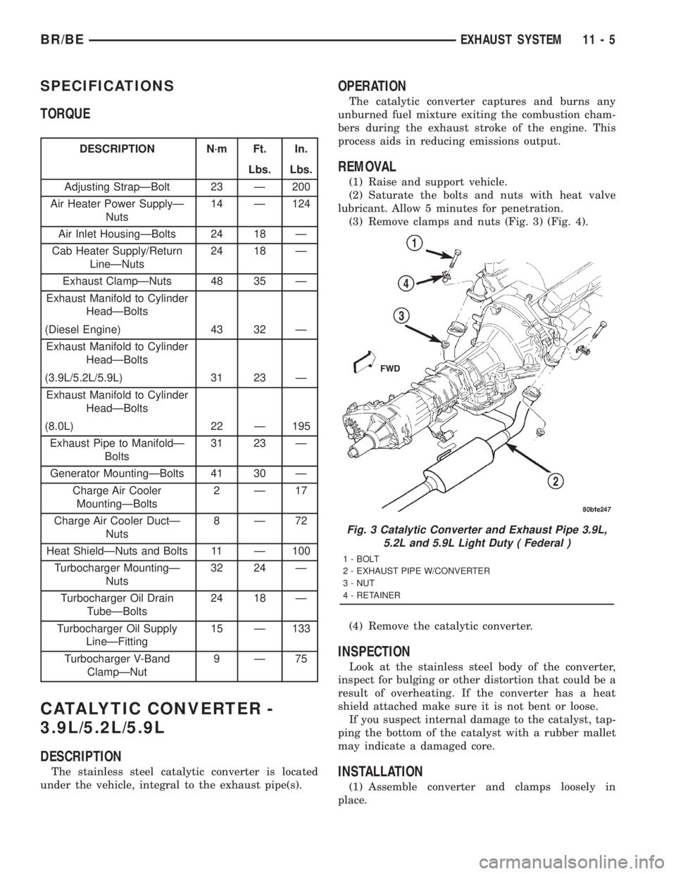
(3) Remove clamps and nuts (Fig. 3) (Fig. 4).
(4) Remove the catalytic converter.
INSPECTION
Look at the stainless steel body of the converter,
inspect for bulging or other distortion that could be a
result of overheating. If the converter has a heat
shield attached make sure it is not bent or loose.
If you suspect internal damage to the catalyst, tap-
ping the bottom of the catalyst with a rubber mallet
may indicate a damaged core.
INSTALLATION
(1) Assemble converter and clamps loosely in
place.
Fig. 3 Catalytic Converter and Exhaust Pipe 3.9L,
5.2L and 5.9L Light Duty ( Federal )
1 - BOLT
2 - EXHAUST PIPE W/CONVERTER
3 - NUT
4 - RETAINER
BR/BEEXHAUST SYSTEM 11 - 5
Page 1472 of 2889
(3)Pre-lube the turbocharger.Pour 50 to 60 cc
(2 to 3 oz.) clean engine oil in the oil supply line fit-
ting. Carefully rotate the turbocharger impeller by
hand to distribute the oil thoroughly.
(4) Install and tighten the oil supply line fitting
nut to 20 N´m (133 in. lbs.) torque.
(5) Position the charge air cooler inlet pipe to the
turbocharger. With the clamp in position, tighten the
clamp nut to 11 N´m (95 in. lbs.) torque.
(6) Position the air inlet hose to the turbocharger
(Fig. 23). Tighten the clamp to 11 N´m (95 in. lbs.)
torque.
(7) Raise vehicle on hoist.
(8) Connect the exhaust pipe to the turbocharger
(Fig. 22) and tighten the bolts to 34 N´m (25 ft. lbs.)
torque.
(9) Lower the vehicle.
(10) Connect the battery negative cables.
(11) Start the engine to check for leaks.
CHARGE AIR COOLER AND
PLUMBING
DESCRIPTION
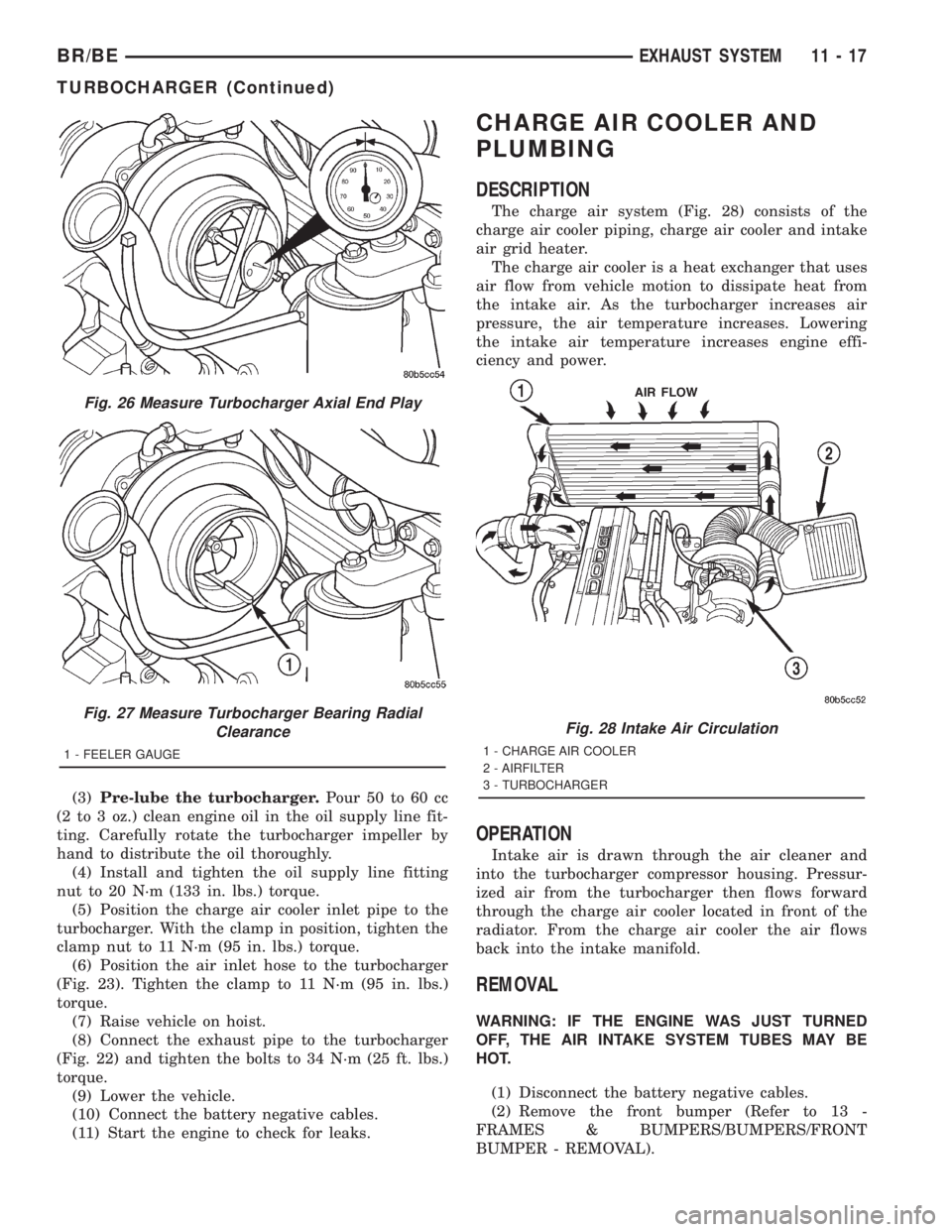
The charge air system (Fig. 28) consists of the
charge air cooler piping, charge air cooler and intake
air grid heater.
The charge air cooler is a heat exchanger that uses
air flow from vehicle motion to dissipate heat from
the intake air. As the turbocharger increases air
pressure, the air temperature increases. Lowering
the intake air temperature increases engine effi-
ciency and power.
OPERATION
Intake air is drawn through the air cleaner and
into the turbocharger compressor housing. Pressur-
ized air from the turbocharger then flows forward
through the charge air cooler located in front of the
radiator. From the charge air cooler the air flows
back into the intake manifold.
REMOVAL
WARNING: IF THE ENGINE WAS JUST TURNED
OFF, THE AIR INTAKE SYSTEM TUBES MAY BE
HOT.
(1) Disconnect the battery negative cables.
(2) Remove the front bumper (Refer to 13 -
FRAMES & BUMPERS/BUMPERS/FRONT
BUMPER - REMOVAL).
Fig. 26 Measure Turbocharger Axial End Play
Fig. 27 Measure Turbocharger Bearing Radial
Clearance
1 - FEELER GAUGE
Fig. 28 Intake Air Circulation
1 - CHARGE AIR COOLER
2 - AIRFILTER
3 - TURBOCHARGER
BR/BEEXHAUST SYSTEM 11 - 17
TURBOCHARGER (Continued)
Page 1533 of 2889
(3) Install MAP sensor mounting bolts (screws).
Tighten screws to 3 N´m (25 in. lbs.) torque.
(4) Install air cleaner.
INSTALLATION - 8.0L
The MAP sensor is mounted into the right upper
side of the intake manifold (Fig. 38). A rubber gasket
is used to seal the sensor to the intake manifold. The
rubber gasket is part of the sensor and is not ser-
viced separately.
(1) Check the condition of the sensor seal. Clean
the sensor and lubricate the rubber gasket with clean
engine oil.
(2) Clean the sensor opening in the intake mani-
fold.
(3) Install the sensor into the intake manifold.
(4) Install sensor mounting bolts. Tighten bolts to
2 N´m (20 in. lbs.) torque.
(5) Install the electrical connector to sensor.
O2 SENSOR
DESCRIPTION
The Oxygen Sensors (O2S) are attached to, and
protrude into the vehicle exhaust system. Depending
on the emission package, the vehicle may use a total
of either 2 or 4 sensors.
3.9L/5.2L/Light Duty 5.9L Engine:Four sensors
are used: 2 upstream (referred to as 1/1 and 2/1) and
2 downstream (referred to as 1/2 and 2/2). With this
emission package, the right upstream sensor (2/1) is
located in the right exhaust downpipe just before the
mini-catalytic convertor. The left upstream sensor
(1/1) is located in the left exhaust downpipe just
before the mini-catalytic convertor. The right down-
stream sensor (2/2) is located in the right exhaust
downpipe just after the mini-catalytic convertor, and
before the main catalytic convertor. The left down-
stream sensor (1/2) is located in the left exhaust
downpipe just after the mini-catalytic convertor, and
before the main catalytic convertor.
Medium and Heavy Duty 8.0L V-10 Engine:
Four sensors are used (2 upstream, 1 pre-catalyst
and 1 post-catalyst). With this emission package, the
1/1 upstream sensor (left side) is located in the left
exhaust downpipe before both the pre-catalyst sensor
(1/2), and the main catalytic convertor. The 2/1
upstream sensor (right side) is located in the right
exhaust downpipe before both the pre-catalyst sensor
(1/2), and the main catalytic convertor. The pre-cata-
lyst sensor (1/2) is located after the 1/1 and 2/1 sen-
sors, and just before the main catalytic convertor.
The post-catalyst sensor (1/3) is located just after the
main catalytic convertor.Heavy Duty 5.9L Engine:Two sensors are used.
They arebothreferred to as upstream sensors (left
side is referred to as 1/1 and right side is referred to
as 2/1). With this emission package, a sensor is
located in each of the exhaust downpipes before the
main catalytic convertor.
OPERATION
An O2 sensor is a galvanic battery that provides
the PCM with a voltage signal (0-1 volt) inversely
proportional to the amount of oxygen in the exhaust.
In other words, if the oxygen content is low, the volt-
age output is high; if the oxygen content is high the
output voltage is low. The PCM uses this information
to adjust injector pulse-width to achieve the
14.7±to±1 air/fuel ratio necessary for proper engine
operation and to control emissions.
The O2 sensor must have a source of oxygen from
outside of the exhaust stream for comparison. Cur-
rent O2 sensors receive their fresh oxygen (outside
air) supply through the wire harness. This is why it
is important to never solder an O2 sensor connector,
or pack the connector with grease.
Four wires (circuits) are used on each O2 sensor: a
12±volt feed circuit for the sensor heating element; a
ground circuit for the heater element; a low-noise
sensor return circuit to the PCM, and an input cir-
cuit from the sensor back to the PCM to detect sen-
sor operation.
Oxygen Sensor Heaters/Heater Relays:
Depending on the emissions package, the heating ele-
ments within the sensors will be supplied voltage
from either the ASD relay, or 2 separate oxygen sen-
sor relays. Refer to 8, Wiring Diagrams to determine
which relays are used.
The O2 sensor uses a Positive Thermal Co-efficient
(PTC) heater element. As temperature increases,
resistance increases. At ambient temperatures
around 70ÉF, the resistance of the heating element is
approximately 4.5 ohms. As the sensor's temperature
increases, resistance in the heater element increases.
This allows the heater to maintain the optimum
operating temperature of approximately 930É-1100ÉF
(500É-600É C). Although the sensors operate the
same, there are physical differences, due to the envi-
ronment that they operate in, that keep them from
being interchangeable.
Maintaining correct sensor temperature at all times
allows the system to enter into closed loop operation
sooner. Also, it allows the system to remain in closed
loop operation during periods of extended idle.
In Closed Loop operation, the PCM monitors cer-
tain O2 sensor input(s) along with other inputs, and
adjusts the injector pulse width accordingly. During
Open Loop operation, the PCM ignores the O2 sensor
input. The PCM adjusts injector pulse width based
14 - 46 FUEL INJECTION - GASOLINEBR/BE
MANIFOLD ABSOLUTE PRESSURE SENSOR (Continued)
Page 1541 of 2889
FUEL DELIVERY - DIESEL
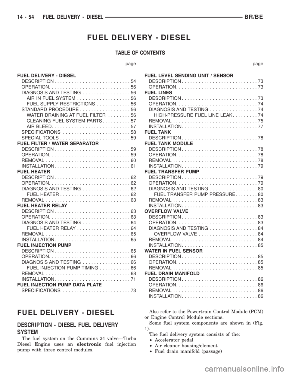
TABLE OF CONTENTS
page page
FUEL DELIVERY - DIESEL
DESCRIPTION...........................54
OPERATION.............................56
DIAGNOSIS AND TESTING.................56
AIR IN FUEL SYSTEM...................56
FUEL SUPPLY RESTRICTIONS............56
STANDARD PROCEDURE..................56
WATER DRAINING AT FUEL FILTER........56
CLEANING FUEL SYSTEM PARTS..........57
AIR BLEED............................57
SPECIFICATIONS........................58
SPECIAL TOOLS.........................59
FUEL FILTER / WATER SEPARATOR
DESCRIPTION...........................59
OPERATION.............................59
REMOVAL..............................60
INSTALLATION...........................61
FUEL HEATER
DESCRIPTION...........................62
OPERATION.............................62
DIAGNOSIS AND TESTING.................62
FUEL HEATER.........................62
REMOVAL..............................63
FUEL HEATER RELAY
DESCRIPTION...........................63
OPERATION.............................63
DIAGNOSIS AND TESTING.................64
FUEL HEATER RELAY...................64
REMOVAL..............................65
INSTALLATION...........................65
FUEL INJECTION PUMP
DESCRIPTION...........................65
OPERATION.............................66
DIAGNOSIS AND TESTING.................66
FUEL INJECTION PUMP TIMING...........66
REMOVAL..............................68
INSTALLATION...........................71
FUEL INJECTION PUMP DATA PLATE
SPECIFICATIONS........................73FUEL LEVEL SENDING UNIT / SENSOR
DESCRIPTION...........................73
OPERATION.............................73
FUEL LINES
DESCRIPTION...........................73
OPERATION.............................74
DIAGNOSIS AND TESTING.................74
HIGH-PRESSURE FUEL LINE LEAK.........74
REMOVAL..............................75
INSTALLATION...........................77
FUEL TANK
DESCRIPTION...........................78
FUEL TANK MODULE
DESCRIPTION...........................78
OPERATION.............................78
REMOVAL..............................78
INSTALLATION...........................79
FUEL TRANSFER PUMP
DESCRIPTION...........................79
OPERATION.............................79
DIAGNOSIS AND TESTING.................80
FUEL TRANSFER PUMP PRESSURE........80
REMOVAL..............................83
INSTALLATION...........................83
OVERFLOW VALVE
DESCRIPTION...........................83
OPERATION.............................83
DIAGNOSIS AND TESTING.................84
OVERFLOW VALVE.....................84
REMOVAL..............................84
INSTALLATION...........................85
WATER IN FUEL SENSOR
DESCRIPTION...........................85
OPERATION.............................85
REMOVAL..............................85
FUEL DRAIN MANIFOLD
DESCRIPTION...........................86
OPERATION.............................86
REMOVAL..............................86
INSTALLATION...........................86
FUEL DELIVERY - DIESEL
DESCRIPTION - DIESEL FUEL DELIVERY
SYSTEM
The fuel system on the Cummins 24 valveÐTurbo
Diesel Engine uses anelectronicfuel injection
pump with three control modules.Also refer to the Powertrain Control Module (PCM)
or Engine Control Module sections.
Some fuel system components are shown in (Fig.
1).
The fuel delivery system consists of the:
²Accelerator pedal
²Air cleaner housing/element
²Fuel drain manifold (passage)
14 - 54 FUEL DELIVERY - DIESELBR/BE
Page 1542 of 2889
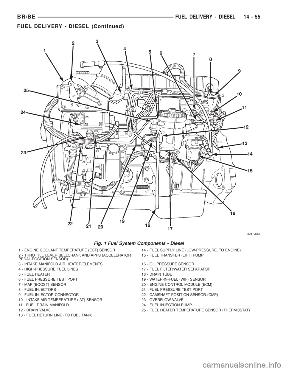
Fig. 1 Fuel System Components - Diesel
1 - ENGINE COOLANT TEMPERATURE (ECT) SENSOR 14 - FUEL SUPPLY LINE (LOW-PRESSURE, TO ENGINE)
2 - THROTTLE LEVER BELLCRANK AND APPS (ACCELERATOR
PEDAL POSITION SENSOR)15 - FUEL TRANSFER (LIFT) PUMP
3 - INTAKE MANIFOLD AIR HEATER/ELEMENTS 16 - OIL PRESSURE SENSOR
4 - HIGH-PRESSURE FUEL LINES 17 - FUEL FILTER/WATER SEPARATOR
5 - FUEL HEATER 18 - DRAIN TUBE
6 - FUEL PRESSURE TEST PORT 19 - WATER-IN-FUEL (WIF) SENSOR
7 - MAP (BOOST) SENSOR 20 - ENGINE CONTROL MODULE (ECM)
8 - FUEL INJECTORS 21 - FUEL PRESSURE TEST PORT
9 - FUEL INJECTOR CONNECTOR 22 - CAMSHAFT POSITION SENSOR (CMP)
10 - INTAKE AIR TEMPERATURE (IAT) SENSOR 23 - OVERFLOW VALVE
11 - FUEL DRAIN MANIFOLD 24 - FUEL INJECTION PUMP
12 - DRAIN VALVE 25 - FUEL HEATER TEMPERATURE SENSOR (THERMOSTAT)
13 - FUEL RETURN LINE (TO FUEL TANK)
BR/BEFUEL DELIVERY - DIESEL 14 - 55
FUEL DELIVERY - DIESEL (Continued)
Page 1543 of 2889
²Fuel filter/water separator
²Fuel heater
²Fuel heater relay
²Fuel transfer (lift) pump
²Fuel injection pump
²Fuel injectors
²Fuel heater temperature sensor
²Fuel tank
²Fuel tank filler/vent tube assembly
²Fuel tank filler tube cap
²Fuel tank module containing the rollover valve,
fuel gauge sending unit (fuel level sensor) and a sep-
arate fuel filter located at bottom of tank module
²Fuel tubes/lines/hoses
²High-pressure fuel injector lines
²In-tank fuel filter (at bottom of fuel tank mod-
ule)
²Low-pressure fuel supply lines
²Low-pressure fuel return line
²Overflow valve
²Quick-connect fittings
²Throttle cable
²Water draining
OPERATION
WARNING: HIGH-PRESSURE FUEL LINES DELIVER
DIESEL FUEL UNDER EXTREME PRESSURE FROM
THE INJECTION PUMP TO THE FUEL INJECTORS.
THIS MAY BE AS HIGH AS 120,000 KPA (17,405
PSI). USE EXTREME CAUTION WHEN INSPECTING
FOR HIGH-PRESSURE FUEL LEAKS. INSPECT FOR
HIGH-PRESSURE FUEL LEAKS WITH A SHEET OF
CARDBOARD. HIGH FUEL INJECTION PRESSURE
CAN CAUSE PERSONAL INJURY IF CONTACT IS
MADE WITH THE SKIN.
DIAGNOSIS AND TESTING - AIR IN FUEL
SYSTEM
Air will enter the fuel system whenever fuel supply
lines, separator filters, injection pump, high-pressure
lines or injectors are removed or disconnected. Air
trapped in the fuel system can result in hard start-
ing, a rough running engine, engine misfire, low
power, excessive smoke and fuel knock. After service
is performed, air must be bled from the system
before starting the engine.Inspect the fuel system from the fuel transfer
pump to the injectors for loose connections. Leaking
fuel is an indicator of loose connections or defective
seals. Air can also enter the fuel system between the
fuel tank and the transfer pump. Inspect the fuel
tank and fuel lines for damage that might allow air
into the system.
For air bleeding, refer to the Air Bleed Procedure.
DIAGNOSIS AND TESTING - FUEL SUPPLY
RESTRICTIONS
LOW-PRESSURE LINES
Fuel supply line restrictions or a defective fuel
transfer pump can cause starting problems and pre-
vent engine from accelerating. The starting problems
include; low power and/or white fog like exhaust.
Test all fuel supply lines for restrictions or block-
age. Flush or replace as necessary. Bleed fuel system
of air once a fuel supply line has been replaced. Refer
to Air Bleed Procedure for procedures.
To test for fuel line restrictions, a vacuum restric-
tion test may be performed. Refer to Fuel Transfer
Pump Pressure Test.
HIGH-PRESSURE LINES
Restricted (kinked or bent) high-pressure lines can
cause starting problems, poor engine performance,
engine mis-fire and white smoke from exhaust.
Examine all high-pressure lines for any damage.
Each radius on each high-pressure line must be
smooth and free of any bends or kinks.
Replace damaged, restricted or leaking high-pres-
sure fuel lines with correct replacement line.
CAUTION: All high-pressure fuel lines must be
clamped securely in place in holders. Lines cannot
contact each other or other components. Do not
attempt to weld high-pressure fuel lines or to repair
lines that are damaged. If line is kinked or bent, it
must be replaced. Use only recommended lines
when replacement of high-pressure fuel line is nec-
essary.
STANDARD PROCEDURES - WATER DRAINING
AT FUEL FILTER
Refer to Fuel Filter/Water Separator removal/in-
stallation for procedures.
14 - 56 FUEL DELIVERY - DIESELBR/BE
FUEL DELIVERY - DIESEL (Continued)