2001 DODGE RAM heater
[x] Cancel search: heaterPage 1389 of 2889
(23) Connect the transmission quick-connect oil
cooler lines to the radiator. Push together until an
audible ªclickº is heard. Verify connection by pulling
apart.
(24) Raise vehicle.
(25) Connect a/c compressor suction/discharge hose
(if a/c equipped).
(26) Install the radiator lower hose and clamps.
(27) Install the starter motor (Refer to 8 - ELEC-
TRICAL/STARTING/STARTER MOTOR - INSTAL-
LATION).
(28) Install the transmission and transfer case (if
equipped).
(29) Connect the exhaust pipe to the turbocharger
elbow (Fig. 3). Torque the bolts to 34 N´m (25 ft. lbs.)
torque.
(30) Connect the transmission auxiliary oil cooler
lines (if equipped).
(31) Lower the vehicle
(32) Connect the heater core supply and return
hoses.
(33) Install the cooling fan and shroud at the same
time (Refer to 7 - COOLING/ENGINE/RADIATOR
FAN - INSTALLATION).
(34) Install the coolant recovery bottle to the fan
shroud (Fig. 2) and connect the hose to the radiator
filler neck.
(35) Install the windshield washer bottle to the fan
shroud and connect the pump supply hose and elec-
trical connections.
(36) Install the radiator upper hose and clamps.
(37) Change oil filter and install new engine oil.
(38) Fill cooling system with coolant (Refer to 7 -
COOLING - STANDARD PROCEDURE).
(39) Connect battery negative cables.
(40) Perform the fuel line air bleed procedure
(Refer to 14 - FUEL SYSTEM/FUEL DELIVERY -
STANDARD PROCEDURE).
(41) Start engine and inspect for engine oil, cool-
ant, and fuel leaks.
INSTALLATIONÐCRANKCASE BREATHER
VAPOR CANISTER
(1) Position vapor canister with strap over stud on
engine front cover. Install retaining nut. Tighten nut
10 N´m ( 89 in. lbs.).
(2) If removed, position hose onto crankcase
breather, then position clamp.
(3) Position lower portion of hose into vapor canis-
ter, then install and tighten cap.
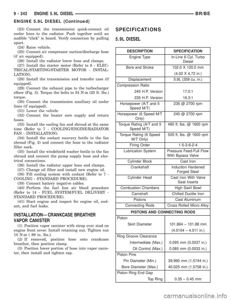
SPECIFICATIONS
5.9L DIESEL
DESCRIPTION SPECIFICATION
Engine Type In-Line 6 Cyl. Turbo
Diesel
Bore and Stroke 102.0 X 120.0 mm
(4.02 X 4.72 in.)
Displacement 5.9L (359 cu. in.)
Compression Ratio
245 H.P. Version 17.0:1
235 H.P. Version 16.3:1
Horsepower (A/T and 5
Speed M/T)235 @ 2700 rpm
Horsepower (6 Speed M/T
Only)245 @ 2700 rpm
Torque Rating (A/T and 5
Speed M/T)460 ft. lbs. @ 1600 rpm
Torque Rating (6 Speed
M/T Only)505 ft. lbs. @ 1600 rpm
Firing Order 1-5-3-6-2-4
Lubrication System Pressure Feed-Full Flow
With Bypass Valve
Cylinder Block Cast Iron
Crankshaft Induction Hardened
Forged Steel
Cylinder Head Cast Iron With Valve
Seat Inserts
Combustion Chambers High Swirl Bowl
Camshaft Chilled Ductile Iron
Pistons Cast Aluminum
Connecting Rods Cross Rolled Micro Alloy
PISTONS AND CONNECTING RODS
Piston
Skirt Diameter 101.864 ± 101.88 mm
(4.0104 ± 4.011 in.)
Ring Groove Clearance
Intermediate (Max.) 0.095 mm (0.0037 in.)
Oil Control (Max.) 0.085 mm (0.0033 in.)
Piston Pins
Pin Diameter (Min.) 39.990 mm (1.5744 in.)
Bore Diameter (Max.) 40.025 mm (1.5758 in.)
Piston Ring End Gap
Top Ring 0.35 ± 0.45 mm
9 - 242 ENGINE 5.9L DIESELBR/BE
ENGINE 5.9L DIESEL (Continued)
Page 1393 of 2889
CYLINDER HEAD
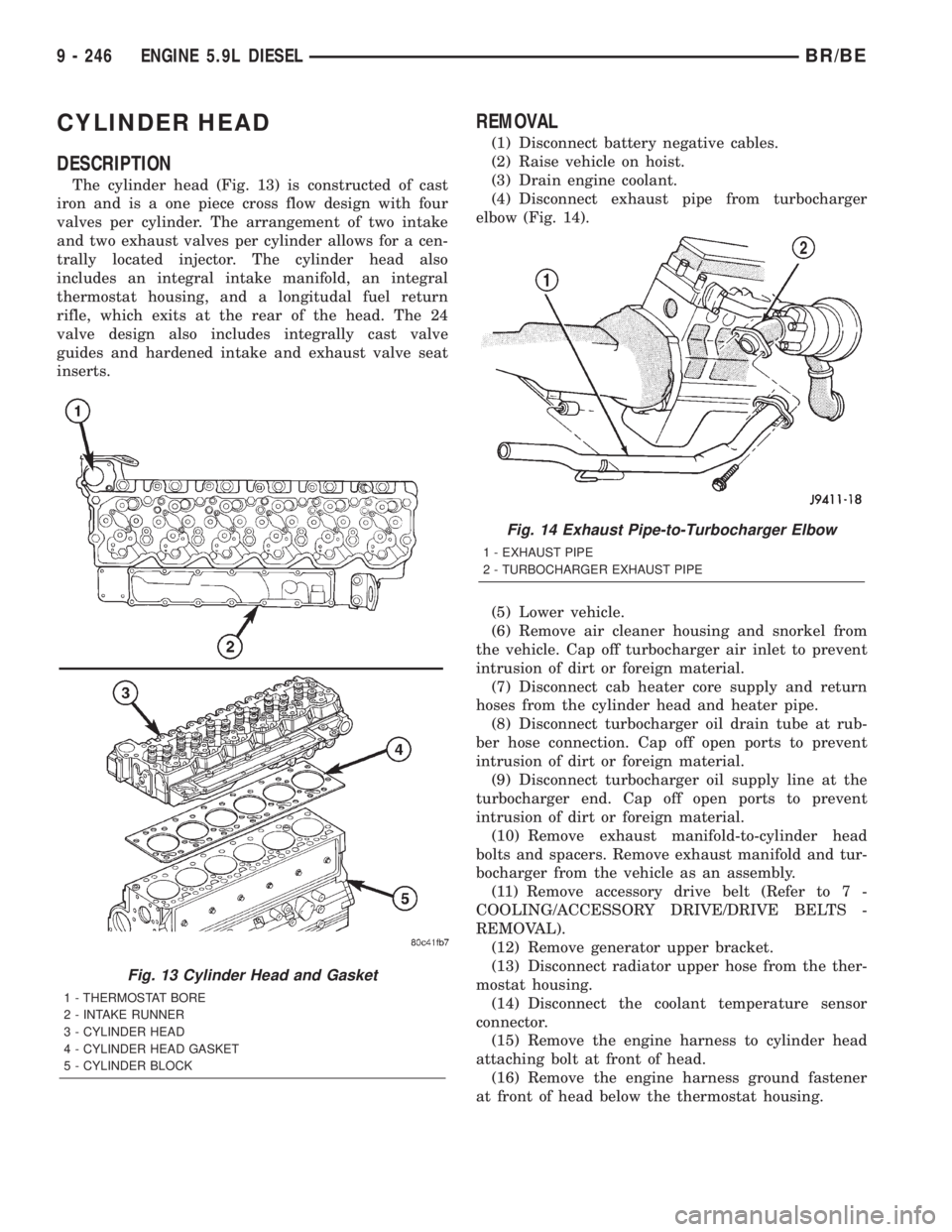
DESCRIPTION
The cylinder head (Fig. 13) is constructed of cast
iron and is a one piece cross flow design with four
valves per cylinder. The arrangement of two intake
and two exhaust valves per cylinder allows for a cen-
trally located injector. The cylinder head also
includes an integral intake manifold, an integral
thermostat housing, and a longitudal fuel return
rifle, which exits at the rear of the head. The 24
valve design also includes integrally cast valve
guides and hardened intake and exhaust valve seat
inserts.
REMOVAL
(1) Disconnect battery negative cables.
(2) Raise vehicle on hoist.
(3) Drain engine coolant.
(4) Disconnect exhaust pipe from turbocharger
elbow (Fig. 14).
(5) Lower vehicle.
(6) Remove air cleaner housing and snorkel from
the vehicle. Cap off turbocharger air inlet to prevent
intrusion of dirt or foreign material.
(7) Disconnect cab heater core supply and return
hoses from the cylinder head and heater pipe.
(8) Disconnect turbocharger oil drain tube at rub-
ber hose connection. Cap off open ports to prevent
intrusion of dirt or foreign material.
(9) Disconnect turbocharger oil supply line at the
turbocharger end. Cap off open ports to prevent
intrusion of dirt or foreign material.
(10) Remove exhaust manifold-to-cylinder head
bolts and spacers. Remove exhaust manifold and tur-
bocharger from the vehicle as an assembly.
(11) Remove accessory drive belt (Refer to 7 -
COOLING/ACCESSORY DRIVE/DRIVE BELTS -
REMOVAL).
(12) Remove generator upper bracket.
(13) Disconnect radiator upper hose from the ther-
mostat housing.
(14) Disconnect the coolant temperature sensor
connector.
(15) Remove the engine harness to cylinder head
attaching bolt at front of head.
(16) Remove the engine harness ground fastener
at front of head below the thermostat housing.
Fig. 13 Cylinder Head and Gasket
1 - THERMOSTAT BORE
2 - INTAKE RUNNER
3 - CYLINDER HEAD
4 - CYLINDER HEAD GASKET
5 - CYLINDER BLOCK
Fig. 14 Exhaust Pipe-to-Turbocharger Elbow
1 - EXHAUST PIPE
2 - TURBOCHARGER EXHAUST PIPE
9 - 246 ENGINE 5.9L DIESELBR/BE
Page 1394 of 2889
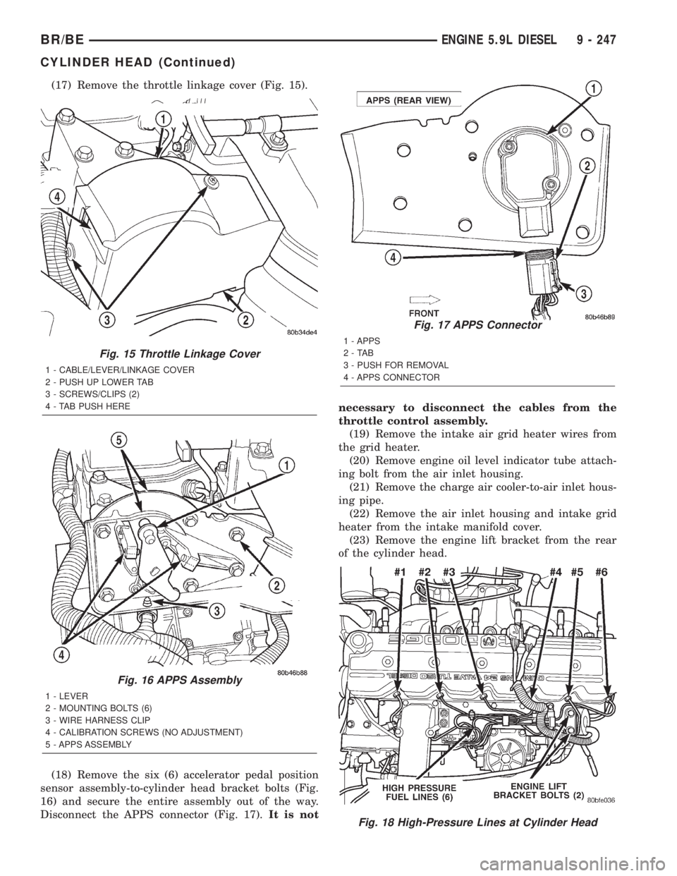
(17) Remove the throttle linkage cover (Fig. 15).
(18) Remove the six (6) accelerator pedal position
sensor assembly-to-cylinder head bracket bolts (Fig.
16) and secure the entire assembly out of the way.
Disconnect the APPS connector (Fig. 17).It is notnecessary to disconnect the cables from the
throttle control assembly.
(19) Remove the intake air grid heater wires from
the grid heater.
(20) Remove engine oil level indicator tube attach-
ing bolt from the air inlet housing.
(21) Remove the charge air cooler-to-air inlet hous-
ing pipe.
(22) Remove the air inlet housing and intake grid
heater from the intake manifold cover.
(23) Remove the engine lift bracket from the rear
of the cylinder head.
Fig. 15 Throttle Linkage Cover
1 - CABLE/LEVER/LINKAGE COVER
2 - PUSH UP LOWER TAB
3 - SCREWS/CLIPS (2)
4 - TAB PUSH HERE
Fig. 16 APPS Assembly
1 - LEVER
2 - MOUNTING BOLTS (6)
3 - WIRE HARNESS CLIP
4 - CALIBRATION SCREWS (NO ADJUSTMENT)
5 - APPS ASSEMBLY
Fig. 17 APPS Connector
1 - APPS
2-TAB
3 - PUSH FOR REMOVAL
4 - APPS CONNECTOR
Fig. 18 High-Pressure Lines at Cylinder Head
BR/BEENGINE 5.9L DIESEL 9 - 247
CYLINDER HEAD (Continued)
Page 1395 of 2889
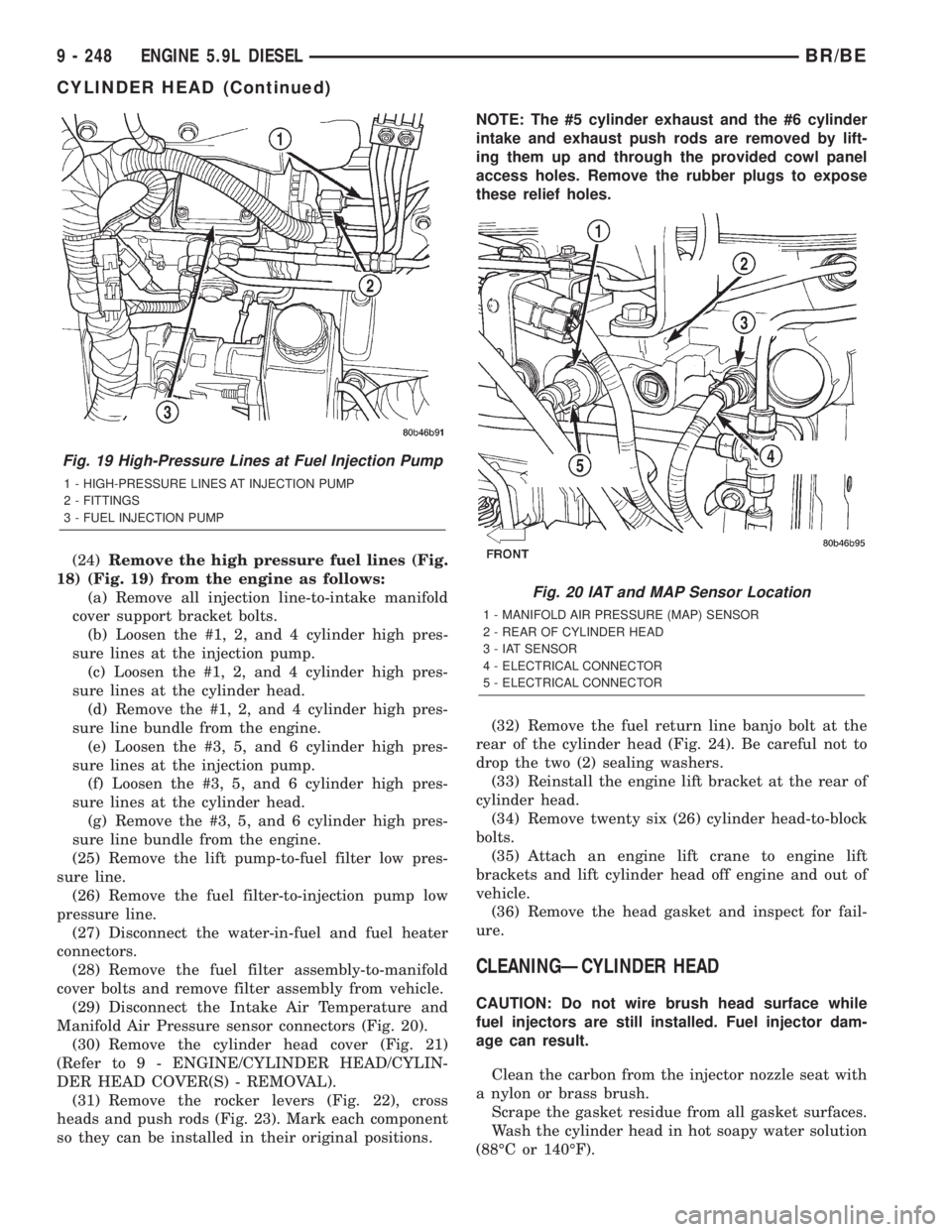
(24)Remove the high pressure fuel lines (Fig.
18) (Fig. 19) from the engine as follows:
(a) Remove all injection line-to-intake manifold
cover support bracket bolts.
(b) Loosen the #1, 2, and 4 cylinder high pres-
sure lines at the injection pump.
(c) Loosen the #1, 2, and 4 cylinder high pres-
sure lines at the cylinder head.
(d) Remove the #1, 2, and 4 cylinder high pres-
sure line bundle from the engine.
(e) Loosen the #3, 5, and 6 cylinder high pres-
sure lines at the injection pump.
(f) Loosen the #3, 5, and 6 cylinder high pres-
sure lines at the cylinder head.
(g) Remove the #3, 5, and 6 cylinder high pres-
sure line bundle from the engine.
(25) Remove the lift pump-to-fuel filter low pres-
sure line.
(26) Remove the fuel filter-to-injection pump low
pressure line.
(27) Disconnect the water-in-fuel and fuel heater
connectors.
(28) Remove the fuel filter assembly-to-manifold
cover bolts and remove filter assembly from vehicle.
(29) Disconnect the Intake Air Temperature and
Manifold Air Pressure sensor connectors (Fig. 20).
(30) Remove the cylinder head cover (Fig. 21)
(Refer to 9 - ENGINE/CYLINDER HEAD/CYLIN-
DER HEAD COVER(S) - REMOVAL).
(31) Remove the rocker levers (Fig. 22), cross
heads and push rods (Fig. 23). Mark each component
so they can be installed in their original positions.NOTE: The #5 cylinder exhaust and the #6 cylinder
intake and exhaust push rods are removed by lift-
ing them up and through the provided cowl panel
access holes. Remove the rubber plugs to expose
these relief holes.
(32) Remove the fuel return line banjo bolt at the
rear of the cylinder head (Fig. 24). Be careful not to
drop the two (2) sealing washers.
(33) Reinstall the engine lift bracket at the rear of
cylinder head.
(34) Remove twenty six (26) cylinder head-to-block
bolts.
(35) Attach an engine lift crane to engine lift
brackets and lift cylinder head off engine and out of
vehicle.
(36) Remove the head gasket and inspect for fail-
ure.
CLEANINGÐCYLINDER HEAD
CAUTION: Do not wire brush head surface while
fuel injectors are still installed. Fuel injector dam-
age can result.
Clean the carbon from the injector nozzle seat with
a nylon or brass brush.
Scrape the gasket residue from all gasket surfaces.
Wash the cylinder head in hot soapy water solution
(88ÉC or 140ÉF).
Fig. 19 High-Pressure Lines at Fuel Injection Pump
1 - HIGH-PRESSURE LINES AT INJECTION PUMP
2 - FITTINGS
3 - FUEL INJECTION PUMP
Fig. 20 IAT and MAP Sensor Location
1 - MANIFOLD AIR PRESSURE (MAP) SENSOR
2 - REAR OF CYLINDER HEAD
3 - IAT SENSOR
4 - ELECTRICAL CONNECTOR
5 - ELECTRICAL CONNECTOR
9 - 248 ENGINE 5.9L DIESELBR/BE
CYLINDER HEAD (Continued)
Page 1398 of 2889
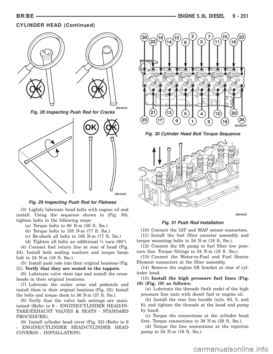
(3) Lightly lubricate head bolts with engine oil and
install. Using the sequence shown in (Fig. 30),
tighten bolts in the following steps:
(a) Torque bolts to 80 N´m (59 ft. lbs.)
(b) Torque bolts to 105 N´m (77 ft. lbs.)
(c) Re-check all bolts to 105 N´m (77 ft. lbs.)
(d) Tighten all bolts an additional ò turn (90É)
(4) Connect fuel return line at rear of head (Fig.
24). Install both sealing washers and torque banjo
bolt to 24 N´m (18 ft. lbs.).
(5)
Install push rods into their original locations (Fig.
31).Verify that they are seated in the tappets
.
(6) Lubricate valve stem tips and install the cross-
heads in their original locations.
(7)
Lubricate the rocker arms and pedestals and
install them in their original locations (Fig. 32). Install
the bolts and torque them to 36 N´m (27 ft. lbs.).
(8) Verify that the valve lash settings are main-
tained (Refer to 9 - ENGINE/CYLINDER HEAD/IN-
TAKE/EXHAUST VALVES & SEATS - STANDARD
PROCEDURE).
(9) Install cylinder head cover (Fig. 33) (Refer to 9
- ENGINE/CYLINDER HEAD/CYLINDER HEAD
COVER(S) - INSTALLATION).(10) Connect the IAT and MAP sensor connectors.
(11) Install the fuel filter canister assembly and
torque mounting bolts to 24 N´m (18 ft. lbs.).
(12) Connect the lift pump to fuel filter low pres-
sure line. Torque fittings to 24 N´m (18 ft. lbs.).
(13) Connect the Water-in-Fuel and Fuel Heater
Element connectors at the filter assembly.
(14) Remove the engine lift bracket at rear of cyl-
inder head.
(15)Install the high pressure fuel lines (Fig.
18) (Fig. 19) as follows:
(a) Lubricate the threads (both ends) of the high
pressure line nuts with diesel fuel or engine oil.
(b) Install the rear line bundle (cyls. #3, 5, and
6), and tighten the threads at the head and pump
by hand.
(c) Torque the connections at the cylinder head
first. Torque connections to 38 N´m (28 ft. lbs.).
(d) Torque the line connections at the injection
pump to 24 N´m (18 ft. lbs.).
Fig. 28 Inspecting Push Rod for Cracks
Fig. 29 Inspecting Push Rod for Flatness
Fig. 30 Cylinder Head Bolt Torque Sequence
Fig. 31 Push Rod Installation
BR/BEENGINE 5.9L DIESEL 9 - 251
CYLINDER HEAD (Continued)
Page 1399 of 2889
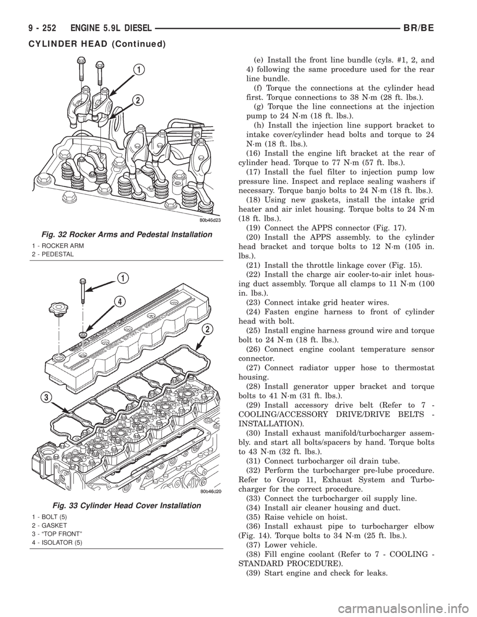
(e) Install the front line bundle (cyls. #1, 2, and
4) following the same procedure used for the rear
line bundle.
(f) Torque the connections at the cylinder head
first. Torque connections to 38 N´m (28 ft. lbs.).
(g) Torque the line connections at the injection
pump to 24 N´m (18 ft. lbs.).
(h) Install the injection line support bracket to
intake cover/cylinder head bolts and torque to 24
N´m (18 ft. lbs.).
(16) Install the engine lift bracket at the rear of
cylinder head. Torque to 77 N´m (57 ft. lbs.).
(17) Install the fuel filter to injection pump low
pressure line. Inspect and replace sealing washers if
necessary. Torque banjo bolts to 24 N´m (18 ft. lbs.).
(18) Using new gaskets, install the intake grid
heater and air inlet housing. Torque bolts to 24 N´m
(18 ft. lbs.).
(19) Connect the APPS connector (Fig. 17).
(20) Install the APPS assembly. to the cylinder
head bracket and torque bolts to 12 N´m (105 in.
lbs.).
(21) Install the throttle linkage cover (Fig. 15).
(22) Install the charge air cooler-to-air inlet hous-
ing duct assembly. Torque all clamps to 11 N´m (100
in. lbs.).
(23) Connect intake grid heater wires.
(24) Fasten engine harness to front of cylinder
head with bolt.
(25) Install engine harness ground wire and torque
bolt to 24 N´m (18 ft. lbs.).
(26) Connect engine coolant temperature sensor
connector.
(27) Connect radiator upper hose to thermostat
housing.
(28) Install generator upper bracket and torque
bolts to 41 N´m (31 ft. lbs.).
(29) Install accessory drive belt (Refer to 7 -
COOLING/ACCESSORY DRIVE/DRIVE BELTS -
INSTALLATION).
(30) Install exhaust manifold/turbocharger assem-
bly. and start all bolts/spacers by hand. Torque bolts
to 43 N´m (32 ft. lbs.).
(31) Connect turbocharger oil drain tube.
(32) Perform the turbocharger pre-lube procedure.
Refer to Group 11, Exhaust System and Turbo-
charger for the correct procedure.
(33) Connect the turbocharger oil supply line.
(34) Install air cleaner housing and duct.
(35) Raise vehicle on hoist.
(36) Install exhaust pipe to turbocharger elbow
(Fig. 14). Torque bolts to 34 N´m (25 ft. lbs.).
(37) Lower vehicle.
(38) Fill engine coolant (Refer to 7 - COOLING -
STANDARD PROCEDURE).
(39) Start engine and check for leaks.
Fig. 32 Rocker Arms and Pedestal Installation
1 - ROCKER ARM
2 - PEDESTAL
Fig. 33 Cylinder Head Cover Installation
1 - BOLT (5)
2 - GASKET
3 - ªTOP FRONTº
4 - ISOLATOR (5)
9 - 252 ENGINE 5.9L DIESELBR/BE
CYLINDER HEAD (Continued)
Page 1448 of 2889
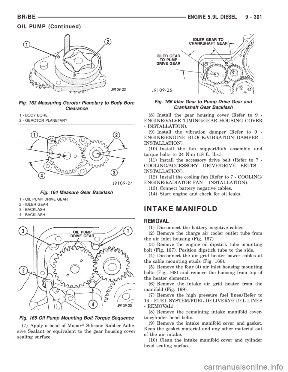
(7) Apply a bead of MopartSilicone Rubber Adhe-
sive Sealant or equivalent to the gear housing cover
sealing surface.(8) Install the gear housing cover (Refer to 9 -
ENGINE/VALVE TIMING/GEAR HOUSING COVER
- INSTALLATION).
(9) Install the vibration damper (Refer to 9 -
ENGINE/ENGINE BLOCK/VIBRATION DAMPER -
INSTALLATION).
(10) Install the fan support/hub assembly and
torque bolts to 24 N´m (18 ft. lbs.).
(11) Install the accessory drive belt (Refer to 7 -
COOLING/ACCESSORY DRIVE/DRIVE BELTS -
INSTALLATION).
(12) Install the cooling fan (Refer to 7 - COOLING/
ENGINE/RADIATOR FAN - INSTALLATION).
(13) Connect battery negative cables.
(14) Start engine and check for oil leaks.
INTAKE MANIFOLD
REMOVAL
(1) Disconnect the battery negative cables.
(2) Remove the charge air cooler outlet tube from
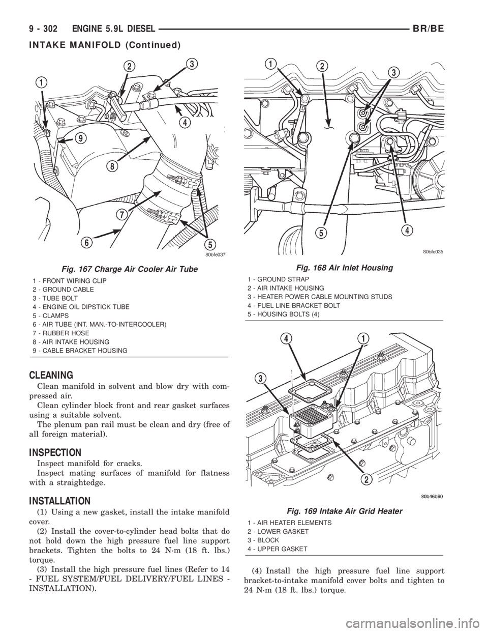
the air inlet housing (Fig. 167).
(3) Remove the engine oil dipstick tube mounting
bolt (Fig. 167). Position dipstick tube to the side.
(4) Disconnect the air grid heater power cables at
the cable mounting studs (Fig. 168).
(5) Remove the four (4) air inlet housing mounting
bolts (Fig. 168) and remove the housing from top of
the heater elements.
(6) Remove the intake air grid heater from the
manifold (Fig. 169).
(7) Remove the high pressure fuel lines.(Refer to
14 - FUEL SYSTEM/FUEL DELIVERY/FUEL LINES
- REMOVAL).
(8) Remove the remaining intake manifold cover-
to-cylinder head bolts.
(9) Remove the intake manifold cover and gasket.
Keep the gasket material and any other material out
of the air intake.
(10) Clean the intake manifold cover and cylinder
head sealing surface.
Fig. 163 Measuring Gerotor Planetary to Body Bore
Clearance
1 - BODY BORE
2 - GEROTOR PLANETARY
Fig. 164 Measure Gear Backlash
1 - OIL PUMP DRIVE GEAR
2 - IDLER GEAR
3 - BACKLASH
4 - BACKLASH
Fig. 165 Oil Pump Mounting Bolt Torque Sequence
Fig. 166 Idler Gear to Pump Drive Gear and
Crankshaft Gear Backlash
BR/BEENGINE 5.9L DIESEL 9 - 301
OIL PUMP (Continued)
Page 1449 of 2889
CLEANING
Clean manifold in solvent and blow dry with com-
pressed air.
Clean cylinder block front and rear gasket surfaces
using a suitable solvent.
The plenum pan rail must be clean and dry (free of
all foreign material).
INSPECTION
Inspect manifold for cracks.
Inspect mating surfaces of manifold for flatness
with a straightedge.
INSTALLATION
(1) Using a new gasket, install the intake manifold
cover.
(2) Install the cover-to-cylinder head bolts that do
not hold down the high pressure fuel line support
brackets. Tighten the bolts to 24 N´m (18 ft. lbs.)
torque.
(3) Install the high pressure fuel lines (Refer to 14
- FUEL SYSTEM/FUEL DELIVERY/FUEL LINES -
INSTALLATION).(4) Install the high pressure fuel line support
bracket-to-intake manifold cover bolts and tighten to
24 N´m (18 ft. lbs.) torque.
Fig. 167 Charge Air Cooler Air Tube
1 - FRONT WIRING CLIP
2 - GROUND CABLE
3 - TUBE BOLT
4 - ENGINE OIL DIPSTICK TUBE
5 - CLAMPS
6 - AIR TUBE (INT. MAN.-TO-INTERCOOLER)
7 - RUBBER HOSE
8 - AIR INTAKE HOUSING
9 - CABLE BRACKET HOUSING
Fig. 168 Air Inlet Housing
1 - GROUND STRAP
2 - AIR INTAKE HOUSING
3 - HEATER POWER CABLE MOUNTING STUDS
4 - FUEL LINE BRACKET BOLT
5 - HOUSING BOLTS (4)
Fig. 169 Intake Air Grid Heater
1 - AIR HEATER ELEMENTS
2 - LOWER GASKET
3 - BLOCK
4 - UPPER GASKET
9 - 302 ENGINE 5.9L DIESELBR/BE
INTAKE MANIFOLD (Continued)