2001 DODGE RAM heater
[x] Cancel search: heaterPage 1339 of 2889
COOLING SYSTEM TESTER METHOD
WARNING: WITH COOLING SYSTEM TESTER IN
PLACE, PRESSURE WILL BUILD UP FAST. EXCES-
SIVE PRESSURE BUILT UP, BY CONTINUOUS
ENGINE OPERATION, MUST BE RELEASED TO A
SAFE PRESSURE POINT. NEVER PERMIT PRES-
SURE TO EXCEED 138 kPa (20 psi).
Install Cooling System Tester 7700 or equivalent to
pressure cap neck. Start the engine and observe the
tester's pressure gauge. If gauge pulsates with every
power stroke of a cylinder a combustion pressure
leak is evident.
CHEMICAL TEST METHOD
Combustion leaks into the cooling system can also
be checked by using Bloc-Chek Kit C-3685-A or
equivalent. Perform test following the procedures
supplied with the tool kit.
REMOVAL
(1) Disconnect the negative cable from the battery.
(2) Drain cooling system (Refer to 7 - COOLING -
STANDARD PROCEDURE).
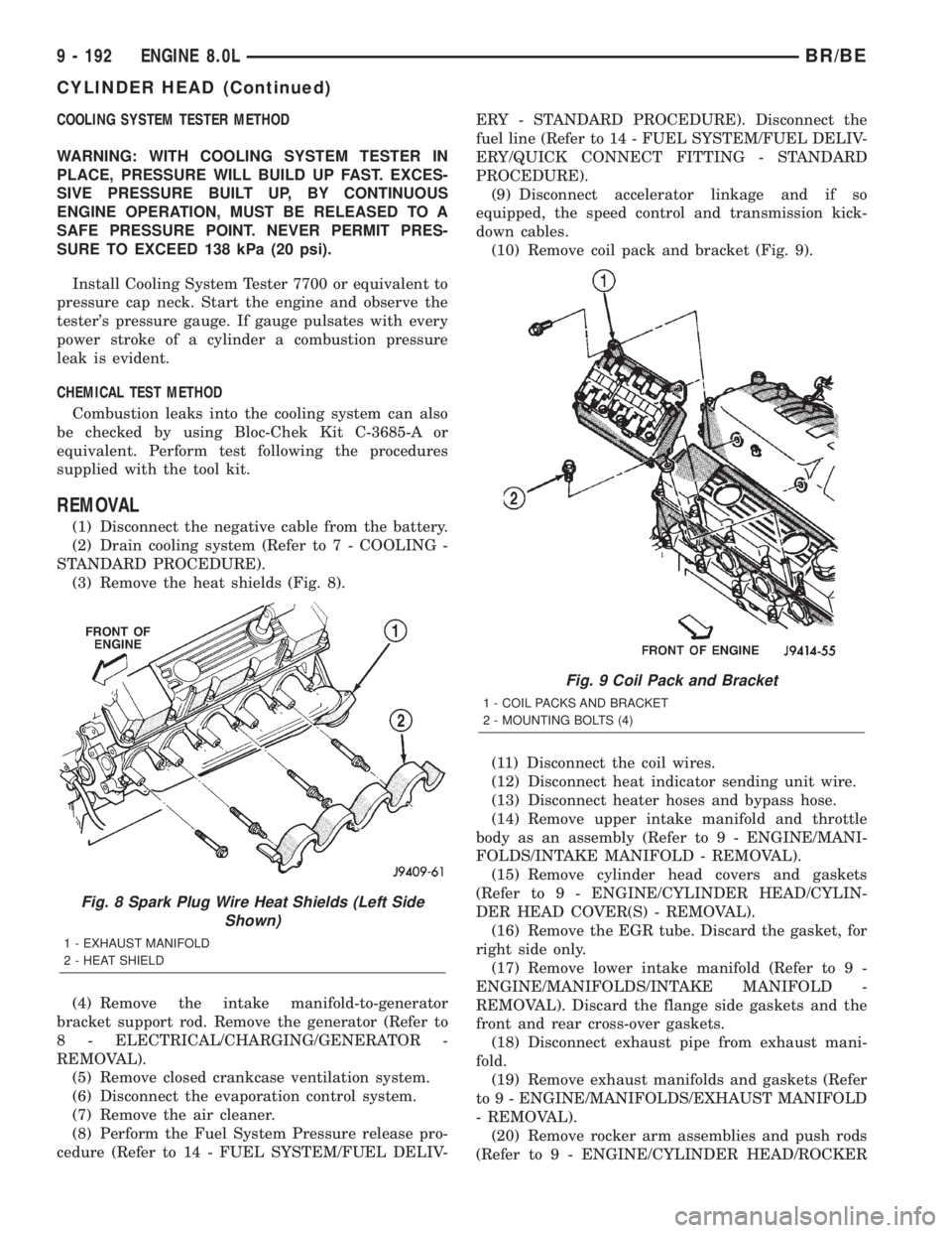
(3) Remove the heat shields (Fig. 8).
(4) Remove the intake manifold-to-generator
bracket support rod. Remove the generator (Refer to
8 - ELECTRICAL/CHARGING/GENERATOR -
REMOVAL).
(5) Remove closed crankcase ventilation system.
(6) Disconnect the evaporation control system.
(7) Remove the air cleaner.
(8) Perform the Fuel System Pressure release pro-
cedure (Refer to 14 - FUEL SYSTEM/FUEL DELIV-ERY - STANDARD PROCEDURE). Disconnect the
fuel line (Refer to 14 - FUEL SYSTEM/FUEL DELIV-
ERY/QUICK CONNECT FITTING - STANDARD
PROCEDURE).
(9) Disconnect accelerator linkage and if so
equipped, the speed control and transmission kick-
down cables.
(10) Remove coil pack and bracket (Fig. 9).
(11) Disconnect the coil wires.
(12) Disconnect heat indicator sending unit wire.
(13) Disconnect heater hoses and bypass hose.
(14) Remove upper intake manifold and throttle
body as an assembly (Refer to 9 - ENGINE/MANI-
FOLDS/INTAKE MANIFOLD - REMOVAL).
(15) Remove cylinder head covers and gaskets
(Refer to 9 - ENGINE/CYLINDER HEAD/CYLIN-
DER HEAD COVER(S) - REMOVAL).
(16) Remove the EGR tube. Discard the gasket, for
right side only.
(17) Remove lower intake manifold (Refer to 9 -
ENGINE/MANIFOLDS/INTAKE MANIFOLD -
REMOVAL). Discard the flange side gaskets and the
front and rear cross-over gaskets.
(18) Disconnect exhaust pipe from exhaust mani-
fold.
(19) Remove exhaust manifolds and gaskets (Refer
to 9 - ENGINE/MANIFOLDS/EXHAUST MANIFOLD
- REMOVAL).
(20) Remove rocker arm assemblies and push rods
(Refer to 9 - ENGINE/CYLINDER HEAD/ROCKER
Fig. 8 Spark Plug Wire Heat Shields (Left Side
Shown)
1 - EXHAUST MANIFOLD
2 - HEAT SHIELD
Fig. 9 Coil Pack and Bracket
1 - COIL PACKS AND BRACKET
2 - MOUNTING BOLTS (4)
9 - 192 ENGINE 8.0LBR/BE
CYLINDER HEAD (Continued)
Page 1340 of 2889
ARM / ADJUSTER ASSY - REMOVAL). Identify to
ensure installation in original locations.
(21) Remove the head bolts from each cylinder
head and remove cylinder heads. Discard the cylin-
der head gasket.
(22) Remove spark plugs.
CLEANING
Clean all surfaces of cylinder block and cylinder
heads. Be sure material does not fall into the lifters
and surrounding valley.
Clean cylinder block front and rear gasket surfaces
using a suitable solvent.
Clean the exhaust manifold to cylinder head mat-
ing areas.
INSPECTION
Inspect all surfaces with a straightedge if there is
any reason to suspect leakage. The out-of-flatness
specifications are 0.0007 mm/mm (0.0004 inch/inch),
0.127 mm/152 mm (0.005 inch/6 inches) any direction
or 0.254 mm (0.010 inch) overall across head. If
exceeded, either replace head or lightly machine the
head surface.
The cylinder head surface finish should be
1.78-4.57 microns (15-80 microinches).
Inspect push rods. Replace worn or bent rods.
Inspect rocker arms. Replace if worn or scored.
INSTALLATION
(1) Position the new cylinder head gaskets onto
the cylinder block.
(2) Position the cylinder heads onto head gaskets
and cylinder block.
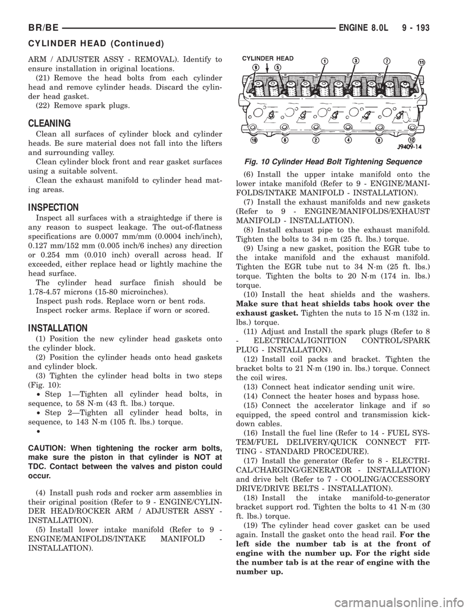
(3) Tighten the cylinder head bolts in two steps
(Fig. 10):
²Step 1ÐTighten all cylinder head bolts, in
sequence, to 58 N´m (43 ft. lbs.) torque.
²Step 2ÐTighten all cylinder head bolts, in
sequence, to 143 N´m (105 ft. lbs.) torque.
²
CAUTION: When tightening the rocker arm bolts,
make sure the piston in that cylinder is NOT at
TDC. Contact between the valves and piston could
occur.
(4) Install push rods and rocker arm assemblies in
their original position (Refer to 9 - ENGINE/CYLIN-
DER HEAD/ROCKER ARM / ADJUSTER ASSY -
INSTALLATION).
(5) Install lower intake manifold (Refer to 9 -
ENGINE/MANIFOLDS/INTAKE MANIFOLD -
INSTALLATION).(6) Install the upper intake manifold onto the
lower intake manifold (Refer to 9 - ENGINE/MANI-
FOLDS/INTAKE MANIFOLD - INSTALLATION).
(7) Install the exhaust manifolds and new gaskets
(Refer to 9 - ENGINE/MANIFOLDS/EXHAUST
MANIFOLD - INSTALLATION).
(8) Install exhaust pipe to the exhaust manifold.
Tighten the bolts to 34 n´m (25 ft. lbs.) torque.
(9) Using a new gasket, position the EGR tube to
the intake manifold and the exhaust manifold.
Tighten the EGR tube nut to 34 N´m (25 ft. lbs.)
torque. Tighten the bolts to 20 N´m (174 in. lbs.)
torque.
(10) Install the heat shields and the washers.
Make sure that heat shields tabs hook over the
exhaust gasket.Tighten the nuts to 15 N´m (132 in.
lbs.) torque.
(11) Adjust and Install the spark plugs (Refer to 8
- ELECTRICAL/IGNITION CONTROL/SPARK
PLUG - INSTALLATION).
(12) Install coil packs and bracket. Tighten the
bracket bolts to 21 N´m (190 in. lbs.) torque. Connect
the coil wires.
(13) Connect heat indicator sending unit wire.
(14) Connect the heater hoses and bypass hose.
(15) Connect the accelerator linkage and if so
equipped, the speed control and transmission kick-
down cables.
(16) Install the fuel line (Refer to 14 - FUEL SYS-
TEM/FUEL DELIVERY/QUICK CONNECT FIT-
TING - STANDARD PROCEDURE).
(17) Install the generator (Refer to 8 - ELECTRI-
CAL/CHARGING/GENERATOR - INSTALLATION)
and drive belt (Refer to 7 - COOLING/ACCESSORY
DRIVE/DRIVE BELTS - INSTALLATION).
(18) Install the intake manifold-to-generator
bracket support rod. Tighten the bolts to 41 N´m (30
ft. lbs.) torque.
(19) The cylinder head cover gasket can be used
again. Install the gasket onto the head rail.For the
left side the number tab is at the front of
engine with the number up. For the right side
the number tab is at the rear of engine with the
number up.
Fig. 10 Cylinder Head Bolt Tightening Sequence
BR/BEENGINE 8.0L 9 - 193
CYLINDER HEAD (Continued)
Page 1370 of 2889
(6) Remove the air cleaner cover and filter.
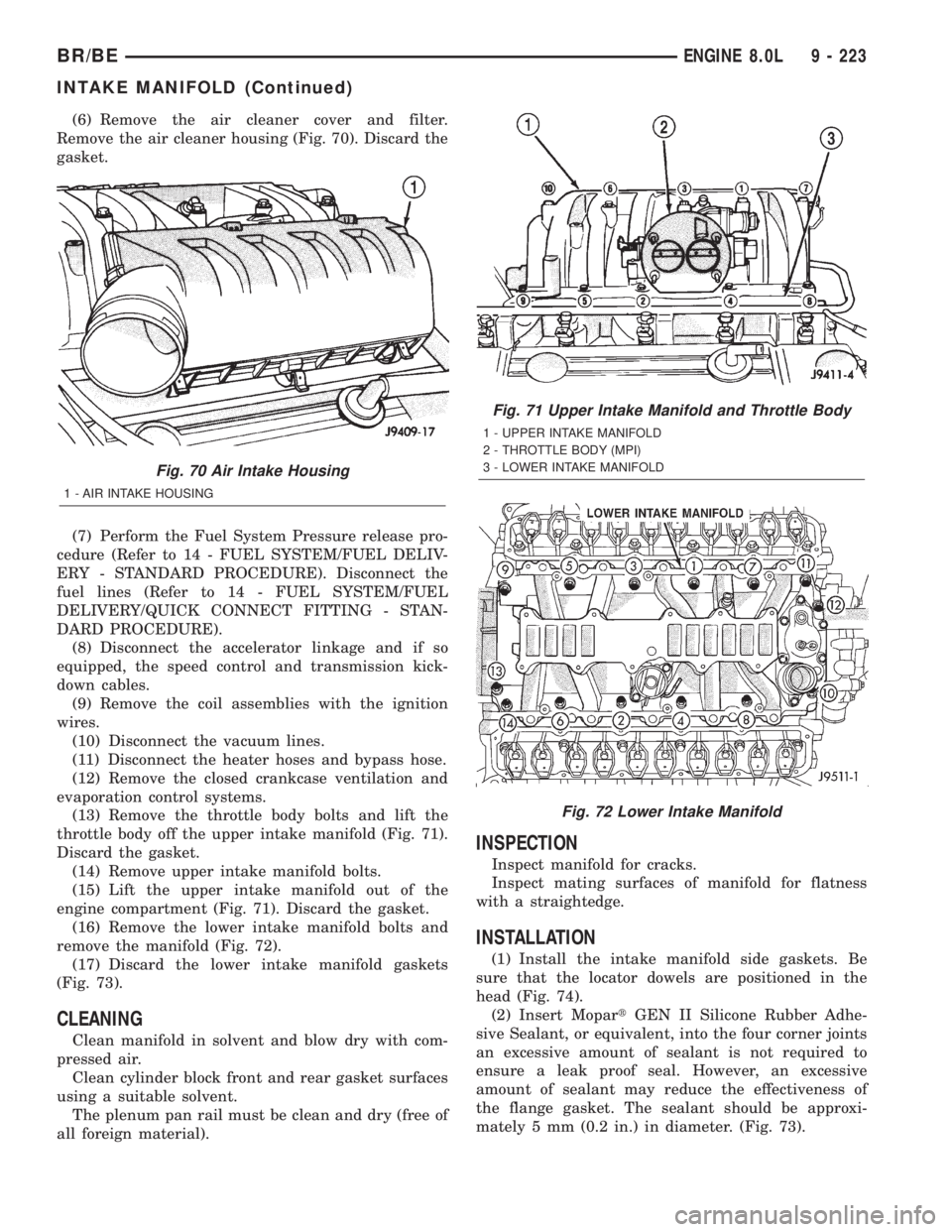
Remove the air cleaner housing (Fig. 70). Discard the
gasket.
(7) Perform the Fuel System Pressure release pro-
cedure (Refer to 14 - FUEL SYSTEM/FUEL DELIV-
ERY - STANDARD PROCEDURE). Disconnect the
fuel lines (Refer to 14 - FUEL SYSTEM/FUEL
DELIVERY/QUICK CONNECT FITTING - STAN-
DARD PROCEDURE).
(8) Disconnect the accelerator linkage and if so
equipped, the speed control and transmission kick-
down cables.
(9) Remove the coil assemblies with the ignition
wires.
(10) Disconnect the vacuum lines.
(11) Disconnect the heater hoses and bypass hose.
(12) Remove the closed crankcase ventilation and
evaporation control systems.
(13) Remove the throttle body bolts and lift the
throttle body off the upper intake manifold (Fig. 71).
Discard the gasket.
(14) Remove upper intake manifold bolts.
(15) Lift the upper intake manifold out of the
engine compartment (Fig. 71). Discard the gasket.
(16) Remove the lower intake manifold bolts and
remove the manifold (Fig. 72).
(17) Discard the lower intake manifold gaskets
(Fig. 73).
CLEANING
Clean manifold in solvent and blow dry with com-
pressed air.
Clean cylinder block front and rear gasket surfaces
using a suitable solvent.
The plenum pan rail must be clean and dry (free of
all foreign material).
INSPECTION
Inspect manifold for cracks.
Inspect mating surfaces of manifold for flatness
with a straightedge.
INSTALLATION
(1) Install the intake manifold side gaskets. Be
sure that the locator dowels are positioned in the
head (Fig. 74).
(2) Insert MopartGEN II Silicone Rubber Adhe-
sive Sealant, or equivalent, into the four corner joints
an excessive amount of sealant is not required to
ensure a leak proof seal. However, an excessive
amount of sealant may reduce the effectiveness of
the flange gasket. The sealant should be approxi-
mately 5 mm (0.2 in.) in diameter. (Fig. 73).
Fig. 70 Air Intake Housing
1 - AIR INTAKE HOUSING
Fig. 71 Upper Intake Manifold and Throttle Body
1 - UPPER INTAKE MANIFOLD
2 - THROTTLE BODY (MPI)
3 - LOWER INTAKE MANIFOLD
Fig. 72 Lower Intake Manifold
BR/BEENGINE 8.0L 9 - 223
INTAKE MANIFOLD (Continued)
Page 1371 of 2889
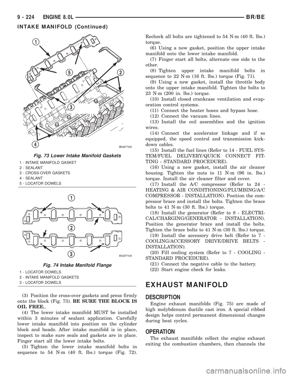
(3) Position the cross-over gaskets and press firmly
onto the block (Fig. 73).BE SURE THE BLOCK IS
OIL FREE..
(4) The lower intake manifold MUST be installed
within 3 minutes of sealant application. Carefully
lower intake manifold into position on the cylinder
block and heads. After intake manifold is in place,
inspect to make sure seals and gaskets are in place.
Finger start all the lower intake bolts.
(5) Tighten the lower intake manifold bolts in
sequence to 54 N´m (40 ft. lbs.) torque (Fig. 72).Recheck all bolts are tightened to 54 N´m (40 ft. lbs.)
torque.
(6) Using a new gasket, position the upper intake
manifold onto the lower intake manifold.
(7) Finger start all bolts, alternate one side to the
other.
(8) Tighten upper intake manifold bolts in
sequence to 22 N´m (16 ft. lbs.) torque (Fig. 71).
(9) Using a new gasket, install the throttle body
onto the upper intake manifold. Tighten the bolts to
23 N´m (200 in. lbs.) torque.
(10) Install closed crankcase ventilation and evap-
oration control systems.
(11) Connect the heater hoses and bypass hose.
(12) Connect the vacuum lines.
(13) Install the coil assemblies and the ignition
wires.
(14) Connect the accelerator linkage and if so
equipped, the speed control and transmission kick-
down cables.
(15) Install the fuel lines (Refer to 14 - FUEL SYS-
TEM/FUEL DELIVERY/QUICK CONNECT FIT-
TING - STANDARD PROCEDURE).
(16) Using a new gasket, install the air cleaner
housing. Tighten the nuts to 11 N´m (96 in. lbs.)
torque. Install the air cleaner filter and cover.
(17) Install the A/C compressor (Refer to 24 -
HEATING & AIR CONDITIONING/PLUMBING/A/C
COMPRESSOR - INSTALLATION). Position the com-
pressor brace and install the bolts. Tighten the brace
bolts to 41 N´m (30 ft. lbs.) torque.
(18) Install the generator (Refer to 8 - ELECTRI-
CAL/CHARGING/GENERATOR - INSTALLATION).
Position the generator brace and install the bolts.
Tighten the brace bolts to 41 N´m (30 ft. lbs.) torque.
(19) Install the accessory drive belt (Refer to 7 -
COOLING/ACCESSORY DRIVE/DRIVE BELTS -
INSTALLATION).
(20) Fill cooling system (Refer to 7 - COOLING -
STANDARD PROCEDURE).
(21) Connect the negative cable to the battery.
(22) Start engine check for leaks.
EXHAUST MANIFOLD
DESCRIPTION
Engine exhaust manifolds (Fig. 75) are made of
high molybdenum ductile cast iron. A special ribbed
design helps control permanent dimensional changes
during heat cycles.
OPERATION
The exhaust manifolds collect the engine exhaust
exiting the combustion chambers, then channels the
Fig. 73 Lower Intake Manifold Gaskets
1 - INTAKE MANIFOLD GASKET
2 - SEALANT
3 - CROSS-OVER GASKETS
4 - SEALANT
5 - LOCATOR DOWELS
Fig. 74 Intake Manifold Flange
1 - LOCATOR DOWELS
2 - INTAKE MANIFOLD GASKETS
3 - LOCATOR DOWELS
9 - 224 ENGINE 8.0LBR/BE
INTAKE MANIFOLD (Continued)
Page 1382 of 2889
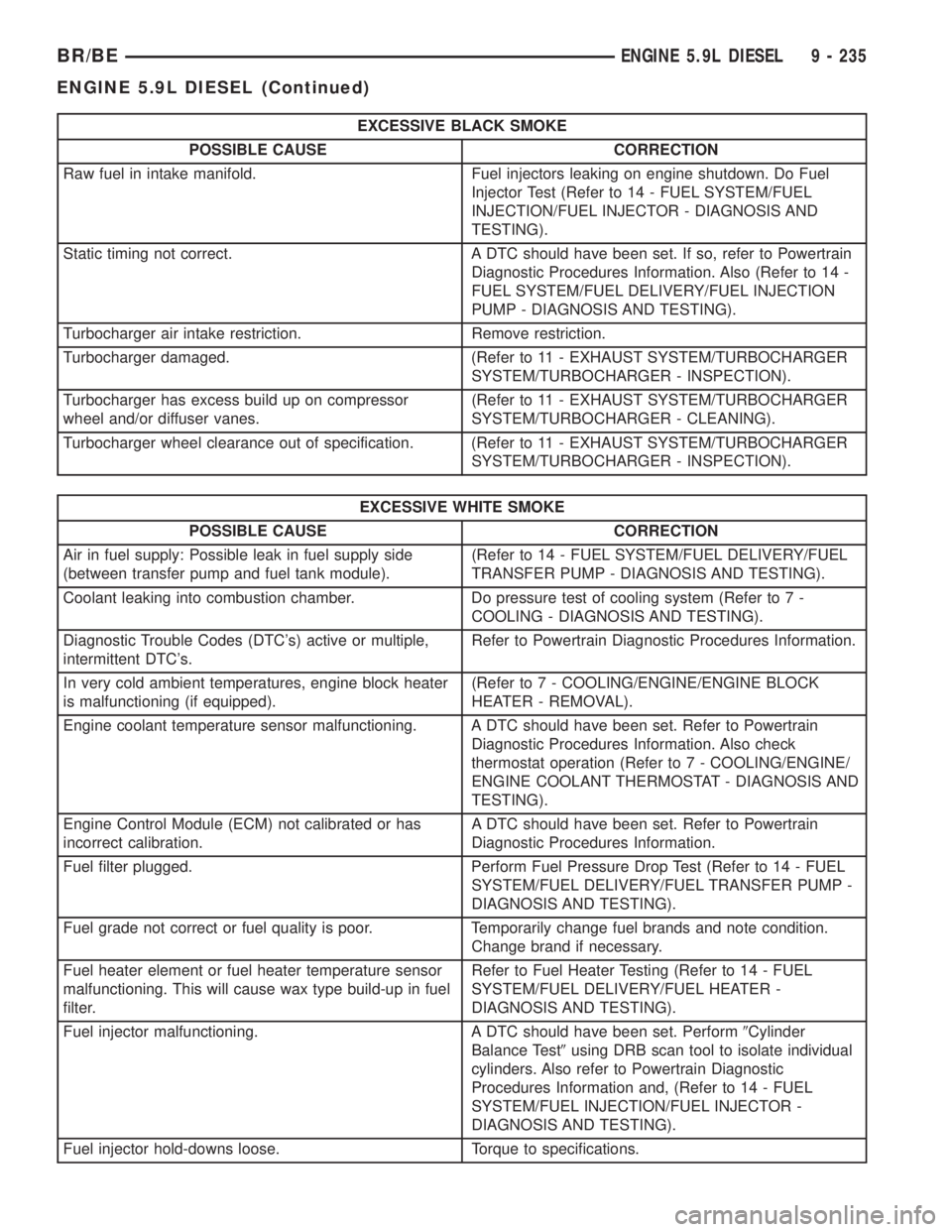
EXCESSIVE BLACK SMOKE
POSSIBLE CAUSE CORRECTION
Raw fuel in intake manifold. Fuel injectors leaking on engine shutdown. Do Fuel
Injector Test (Refer to 14 - FUEL SYSTEM/FUEL
INJECTION/FUEL INJECTOR - DIAGNOSIS AND
TESTING).
Static timing not correct. A DTC should have been set. If so, refer to Powertrain
Diagnostic Procedures Information. Also (Refer to 14 -
FUEL SYSTEM/FUEL DELIVERY/FUEL INJECTION
PUMP - DIAGNOSIS AND TESTING).
Turbocharger air intake restriction. Remove restriction.
Turbocharger damaged. (Refer to 11 - EXHAUST SYSTEM/TURBOCHARGER
SYSTEM/TURBOCHARGER - INSPECTION).
Turbocharger has excess build up on compressor
wheel and/or diffuser vanes.(Refer to 11 - EXHAUST SYSTEM/TURBOCHARGER
SYSTEM/TURBOCHARGER - CLEANING).
Turbocharger wheel clearance out of specification. (Refer to 11 - EXHAUST SYSTEM/TURBOCHARGER
SYSTEM/TURBOCHARGER - INSPECTION).
EXCESSIVE WHITE SMOKE
POSSIBLE CAUSE CORRECTION
Air in fuel supply: Possible leak in fuel supply side
(between transfer pump and fuel tank module).(Refer to 14 - FUEL SYSTEM/FUEL DELIVERY/FUEL
TRANSFER PUMP - DIAGNOSIS AND TESTING).
Coolant leaking into combustion chamber. Do pressure test of cooling system (Refer to 7 -
COOLING - DIAGNOSIS AND TESTING).
Diagnostic Trouble Codes (DTC's) active or multiple,
intermittent DTC's.Refer to Powertrain Diagnostic Procedures Information.
In very cold ambient temperatures, engine block heater
is malfunctioning (if equipped).(Refer to 7 - COOLING/ENGINE/ENGINE BLOCK
HEATER - REMOVAL).
Engine coolant temperature sensor malfunctioning. A DTC should have been set. Refer to Powertrain
Diagnostic Procedures Information. Also check
thermostat operation (Refer to 7 - COOLING/ENGINE/
ENGINE COOLANT THERMOSTAT - DIAGNOSIS AND
TESTING).
Engine Control Module (ECM) not calibrated or has
incorrect calibration.A DTC should have been set. Refer to Powertrain
Diagnostic Procedures Information.
Fuel filter plugged. Perform Fuel Pressure Drop Test (Refer to 14 - FUEL
SYSTEM/FUEL DELIVERY/FUEL TRANSFER PUMP -
DIAGNOSIS AND TESTING).
Fuel grade not correct or fuel quality is poor. Temporarily change fuel brands and note condition.
Change brand if necessary.
Fuel heater element or fuel heater temperature sensor
malfunctioning. This will cause wax type build-up in fuel
filter.Refer to Fuel Heater Testing (Refer to 14 - FUEL
SYSTEM/FUEL DELIVERY/FUEL HEATER -
DIAGNOSIS AND TESTING).
Fuel injector malfunctioning. A DTC should have been set. Perform9Cylinder
Balance Test9using DRB scan tool to isolate individual
cylinders. Also refer to Powertrain Diagnostic
Procedures Information and, (Refer to 14 - FUEL
SYSTEM/FUEL INJECTION/FUEL INJECTOR -
DIAGNOSIS AND TESTING).
Fuel injector hold-downs loose. Torque to specifications.
BR/BEENGINE 5.9L DIESEL 9 - 235
ENGINE 5.9L DIESEL (Continued)
Page 1383 of 2889
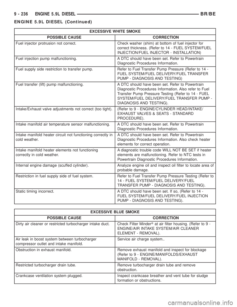
EXCESSIVE WHITE SMOKE
POSSIBLE CAUSE CORRECTION
Fuel injector protrusion not correct. Check washer (shim) at bottom of fuel injector for
correct thickness. (Refer to 14 - FUEL SYSTEM/FUEL
INJECTION/FUEL INJECTOR - INSTALLATION)
Fuel injection pump malfunctioning. A DTC should have been set. Refer to Powertrain
Diagnostic Procedures Information.
Fuel supply side restriction to transfer pump. Refer to Fuel Transfer Pump Pressure (Refer to 14 -
FUEL SYSTEM/FUEL DELIVERY/FUEL TRANSFER
PUMP - DIAGNOSIS AND TESTING)
Fuel transfer (lift) pump malfunctioning. A DTC should have been set. Refer to Powertrain
Diagnostic Procedures Information. Also refer to Fuel
Transfer Pump Pressure Testing (Refer to 14 - FUEL
SYSTEM/FUEL DELIVERY/FUEL TRANSFER PUMP -
DIAGNOSIS AND TESTING).
Intake/Exhaust valve adjustments not correct (too tight). (Refer to 9 - ENGINE/CYLINDER HEAD/INTAKE/
EXHAUST VALVES & SEATS - STANDARD
PROCEDURE).
Intake manifold air temperature sensor malfunctioning. A DTC should have been set. Refer to Powertrain
Diagnostic Procedures Information.
Intake manifold heater circuit not functioning correctly in
cold weather.A DTC should have been set. Refer to Powertrain
Diagnostic Procedures Information. Also check heater
elements for correct operation.
Intake manifold heater elements not functioning
correctly in cold weather.A diagnostic trouble code WILL NOT BE SET if heater
elements are malfunctioning. Refer to NTC tests in
Powertrain Diagnostic Procedures Information.
Internal engine damage (scuffed cylinder). Analyze engine oil and inspect oil filter to locate area of
probable damage.
Restriction in fuel supply side of fuel system. Refer to Fuel Transfer Pump Pressure Testing (Refer to
14 - FUEL SYSTEM/FUEL DELIVERY/FUEL
TRANSFER PUMP - DIAGNOSIS AND TESTING).
Static timing incorrect. A DTC should have been set. If so, (Refer to 14 -
FUEL SYSTEM/FUEL DELIVERY/FUEL INJECTION
PUMP - DIAGNOSIS AND TESTING).
EXCESSIVE BLUE SMOKE
POSSIBLE CAUSE CORRECTION
Dirty air cleaner or restricted turbocharger intake duct. Check Filter MinderTat air filter housing. (Refer to 9 -
ENGINE/AIR INTAKE SYSTEM/AIR CLEANER
ELEMENT - REMOVAL).
Air leak in boost system between turbocharger
compressor outlet and intake manifold.Service air charge system..
Obstruction in exhaust manifold. Remove exhaust manifold and inspect for blockage
(Refer to 9 - ENGINE/MANIFOLDS/EXHAUST
MANIFOLD - REMOVAL).
Restricted turbocharger drain tube. Remove turbocharger drain tube and remove
obstruction.
Crankcase ventilation system plugged. Inspect crankcase breather and vent tube for sludge
formation or obstructions.
9 - 236 ENGINE 5.9L DIESELBR/BE
ENGINE 5.9L DIESEL (Continued)
Page 1386 of 2889
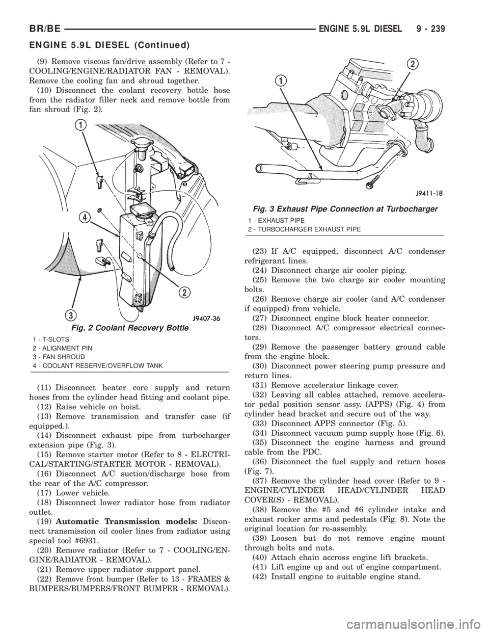
(9) Remove viscous fan/drive assembly (Refer to 7 -
COOLING/ENGINE/RADIATOR FAN - REMOVAL).
Remove the cooling fan and shroud together.
(10) Disconnect the coolant recovery bottle hose
from the radiator filler neck and remove bottle from
fan shroud (Fig. 2).
(11) Disconnect heater core supply and return
hoses from the cylinder head fitting and coolant pipe.
(12) Raise vehicle on hoist.
(13) Remove transmission and transfer case (if
equipped.).
(14) Disconnect exhaust pipe from turbocharger
extension pipe (Fig. 3).
(15) Remove starter motor (Refer to 8 - ELECTRI-
CAL/STARTING/STARTER MOTOR - REMOVAL).
(16) Disconnect A/C suction/discharge hose from
the rear of the A/C compressor.
(17) Lower vehicle.
(18) Disconnect lower radiator hose from radiator
outlet.
(19)Automatic Transmission models:Discon-
nect transmission oil cooler lines from radiator using
special tool #6931.
(20) Remove radiator (Refer to 7 - COOLING/EN-
GINE/RADIATOR - REMOVAL).
(21) Remove upper radiator support panel.
(22)
Remove front bumper (Refer to 13 - FRAMES &
BUMPERS/BUMPERS/FRONT BUMPER - REMOVAL).
(23) If A/C equipped, disconnect A/C condenser
refrigerant lines.
(24) Disconnect charge air cooler piping.
(25) Remove the two charge air cooler mounting
bolts.
(26) Remove charge air cooler (and A/C condenser
if equipped) from vehicle.
(27) Disconnect engine block heater connector.
(28) Disconnect A/C compressor electrical connec-
tors.
(29) Remove the passenger battery ground cable
from the engine block.
(30) Disconnect power steering pump pressure and
return lines.
(31) Remove accelerator linkage cover.
(32) Leaving all cables attached, remove accelera-
tor pedal position sensor assy. (APPS) (Fig. 4) from
cylinder head bracket and secure out of the way.
(33) Disconnect APPS connector (Fig. 5).
(34) Disconnect vacuum pump supply hose (Fig. 6).
(35) Disconnect the engine harness and ground
cable from the PDC.
(36) Disconnect the fuel supply and return hoses
(Fig. 7).
(37) Remove the cylinder head cover (Refer to 9 -
ENGINE/CYLINDER HEAD/CYLINDER HEAD
COVER(S) - REMOVAL).
(38) Remove the #5 and #6 cylinder intake and
exhaust rocker arms and pedestals (Fig. 8). Note the
original location for re-assembly.
(39) Loosen but do not remove engine mount
through bolts and nuts.
(40) Attach chain accross engine lift brackets.
(41)
Lift engine up and out of engine compartment.
(42) Install engine to suitable engine stand.
Fig. 2 Coolant Recovery Bottle
1 - T-SLOTS
2 - ALIGNMENT PIN
3 - FAN SHROUD
4 - COOLANT RESERVE/OVERFLOW TANK
Fig. 3 Exhaust Pipe Connection at Turbocharger
1 - EXHAUST PIPE
2 - TURBOCHARGER EXHAUST PIPE
BR/BEENGINE 5.9L DIESEL 9 - 239
ENGINE 5.9L DIESEL (Continued)
Page 1388 of 2889
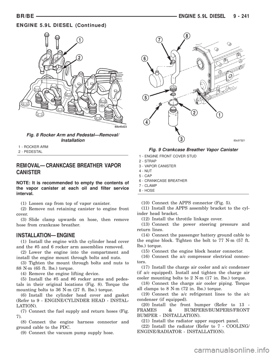
REMOVALÐCRANKCASE BREATHER VAPOR
CANISTER
NOTE: It is recommended to empty the contents of
the vapor canister at each oil and filter service
interval.
(1) Loosen cap from top of vapor canister.
(2) Remove nut retaining canister to engine front
cover.
(3) Slide clamp upwards on hose, then remove
hose from crankcase breather.
INSTALLATIONÐENGINE
(1) Install the engine with the cylinder head cover
and the #5 and 6 rocker arm assemblies removed.
(2) Lower the engine into the compartment and
install the engine mount through bolts and nuts.
(3) Tighten the mount through bolts and nuts to
88 N´m (65 ft. lbs.) torque.
(4) Remove the engine lifting device.
(5) Install the #5 and #6 rocker arms and pedes-
tals in their original locations (Fig. 8). Torque the
mounting bolts to 36 N´m (27 ft. lbs.) torque.
(6) Install the cylinder head cover and gasket
(Refer to 9 - ENGINE/CYLINDER HEAD - INSTAL-
LATION).
(7) Connect the fuel supply and return hoses (Fig.
7).
(8) Connect the engine harness connector and
ground cable to the PDC.
(9) Connect the vacuum pump supply hose.(10) Connect the APPS connector (Fig. 5).
(11) Install the APPS assembly bracket to the cyl-
inder head bracket.
(12) Install the throttle linkage cover.
(13) Connect the power steering pressure and
return lines.
(14) Connect the passenger battery ground cable to
the engine block. Tighten the bolt to 77 N´m (57 ft.
lbs.) torque.
(15) Connect the engine block heater connector.
(16) Connect the a/c compressor electrical connec-
tors.
(17) Install the charge air cooler and a/c condenser
(if a/c equipped). Install and tighten the charge air
cooler mounting bolts to 2 N´m (17 in. lbs.) torque.
(18) Connect the charge air cooler piping. Torque
all clamps to 8 N´m (72 in. lbs.) torque.
(19) Connect the a/c refrigerant lines to the a/c
condenser (if equipped).
(20) Install the front bumper (Refer to 13 -
FRAMES & BUMPERS/BUMPERS/FRONT
BUMPER - INSTALLATION).
(21) Install the radiator upper support panel.
(22) Install the radiator (Refer to 7 - COOLING/
ENGINE/RADIATOR - INSTALLATION).
Fig. 8 Rocker Arm and PedestalÐRemoval/
Installation
1 - ROCKER ARM
2 - PEDESTALFig. 9 Crankcase Breather Vapor Canister
1 - ENGINE FRONT COVER STUD
2 - STRAP
3 - VAPOR CANISTER
4 - NUT
5 - CAP
6 - CRANKCASE BREATHER
7 - CLAMP
8 - HOSE
BR/BEENGINE 5.9L DIESEL 9 - 241
ENGINE 5.9L DIESEL (Continued)