2001 DODGE RAM heater
[x] Cancel search: heaterPage 2764 of 2889
(3) Disengage the demister tubes from each end of
the main demister duct.
(4) Remove the defroster and demister duct unit
from the instrument panel.
REMOVAL - DEFROSTER AND DEMISTER
DUCT ADAPTER
(1) Roll the instrument panel assembly down, but
do not remove it from the vehicle. Refer to Instru-
ment Panel System for the procedures.
(2)
Using a trim stick or another suitable wide flat-
bladed tool, gently pry at the perimeter edges of the
defroster and demister duct adapter to release the snap
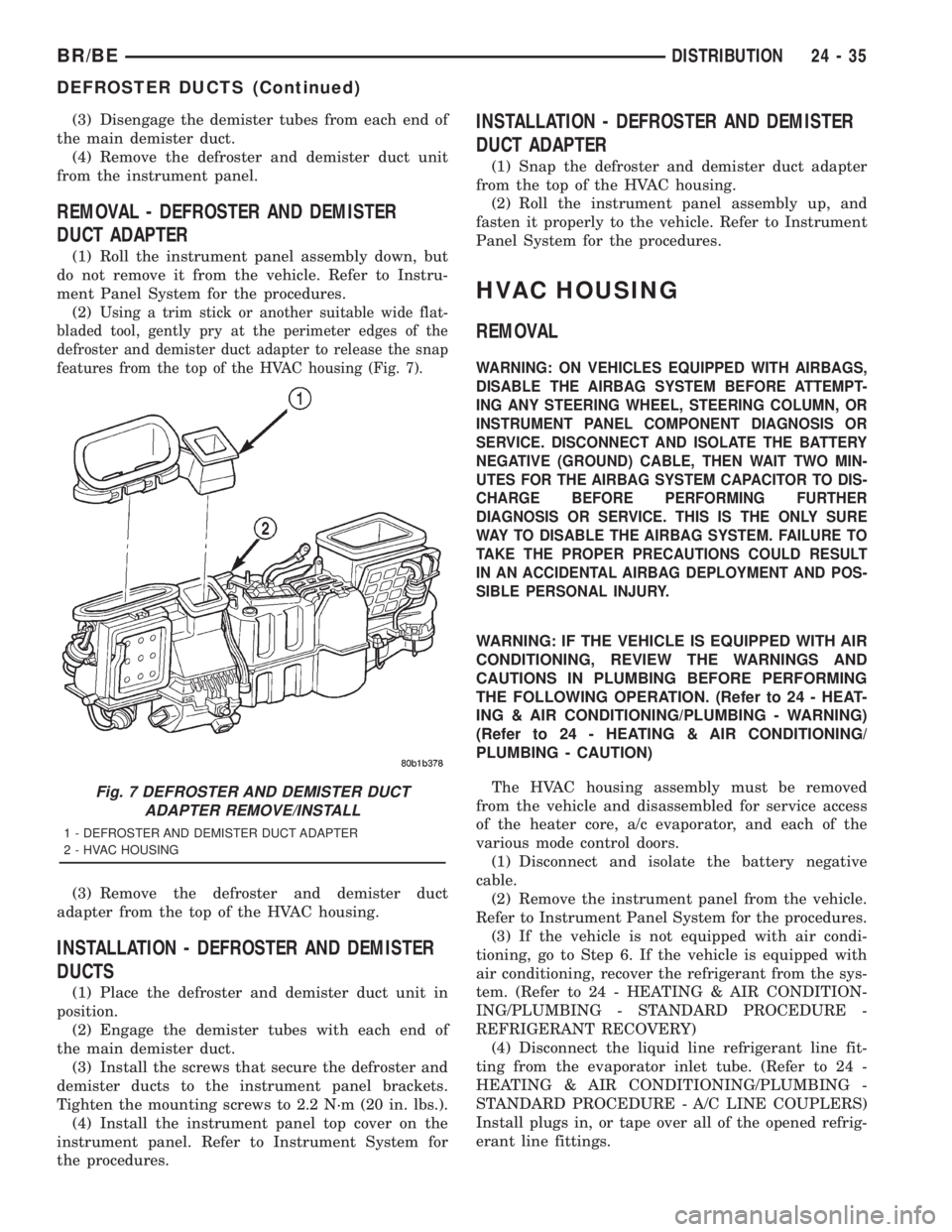
features from the top of the HVAC housing (Fig. 7).
(3) Remove the defroster and demister duct
adapter from the top of the HVAC housing.
INSTALLATION - DEFROSTER AND DEMISTER
DUCTS
(1) Place the defroster and demister duct unit in
position.
(2) Engage the demister tubes with each end of
the main demister duct.
(3) Install the screws that secure the defroster and
demister ducts to the instrument panel brackets.
Tighten the mounting screws to 2.2 N´m (20 in. lbs.).
(4) Install the instrument panel top cover on the
instrument panel. Refer to Instrument System for
the procedures.
INSTALLATION - DEFROSTER AND DEMISTER
DUCT ADAPTER
(1) Snap the defroster and demister duct adapter
from the top of the HVAC housing.
(2) Roll the instrument panel assembly up, and
fasten it properly to the vehicle. Refer to Instrument
Panel System for the procedures.
HVAC HOUSING
REMOVAL
WARNING: ON VEHICLES EQUIPPED WITH AIRBAGS,
DISABLE THE AIRBAG SYSTEM BEFORE ATTEMPT-
ING ANY STEERING WHEEL, STEERING COLUMN, OR
INSTRUMENT PANEL COMPONENT DIAGNOSIS OR
SERVICE. DISCONNECT AND ISOLATE THE BATTERY
NEGATIVE (GROUND) CABLE, THEN WAIT TWO MIN-
UTES FOR THE AIRBAG SYSTEM CAPACITOR TO DIS-
CHARGE BEFORE PERFORMING FURTHER
DIAGNOSIS OR SERVICE. THIS IS THE ONLY SURE
WAY TO DISABLE THE AIRBAG SYSTEM. FAILURE TO
TAKE THE PROPER PRECAUTIONS COULD RESULT
IN AN ACCIDENTAL AIRBAG DEPLOYMENT AND POS-
SIBLE PERSONAL INJURY.
WARNING: IF THE VEHICLE IS EQUIPPED WITH AIR
CONDITIONING, REVIEW THE WARNINGS AND
CAUTIONS IN PLUMBING BEFORE PERFORMING
THE FOLLOWING OPERATION. (Refer to 24 - HEAT-
ING & AIR CONDITIONING/PLUMBING - WARNING)
(Refer to 24 - HEATING & AIR CONDITIONING/
PLUMBING - CAUTION)
The HVAC housing assembly must be removed
from the vehicle and disassembled for service access
of the heater core, a/c evaporator, and each of the
various mode control doors.
(1) Disconnect and isolate the battery negative
cable.
(2) Remove the instrument panel from the vehicle.
Refer to Instrument Panel System for the procedures.
(3) If the vehicle is not equipped with air condi-
tioning, go to Step 6. If the vehicle is equipped with
air conditioning, recover the refrigerant from the sys-
tem. (Refer to 24 - HEATING & AIR CONDITION-
ING/PLUMBING - STANDARD PROCEDURE -
REFRIGERANT RECOVERY)
(4) Disconnect the liquid line refrigerant line fit-
ting from the evaporator inlet tube. (Refer to 24 -
HEATING & AIR CONDITIONING/PLUMBING -
STANDARD PROCEDURE - A/C LINE COUPLERS)
Install plugs in, or tape over all of the opened refrig-
erant line fittings.
Fig. 7 DEFROSTER AND DEMISTER DUCT
ADAPTER REMOVE/INSTALL
1 - DEFROSTER AND DEMISTER DUCT ADAPTER
2 - HVAC HOUSING
BR/BEDISTRIBUTION 24 - 35
DEFROSTER DUCTS (Continued)
Page 2765 of 2889
(5) Remove the accumulator. (Refer to 24 - HEAT-
ING & AIR CONDITIONING/PLUMBING/ACCU-
MULATOR - REMOVAL) Install plugs in, or tape
over all of the opened refrigerant line fittings.
(6) Drain the engine cooling system. Refer to Cool-
ing for the procedures.
(7)
Disconnect the heater hoses from the heater core
tubes. Refer to Cooling for the procedures. Install plugs
in, or tape over the opened heater core tubes.
(8) Remove the Powertrain Control Module (PCM)
from the dash panel and set it aside, but do not
unplug the PCM wire harness connectors. Refer to
Electronic Control Modules for the procedures.
(9) Remove the nuts from the HVAC housing
mounting studs on the engine compartment side of
the dash panel.
(10) Remove the nuts that secure the HVAC hous-
ing to the mounting studs on the passenger compart-
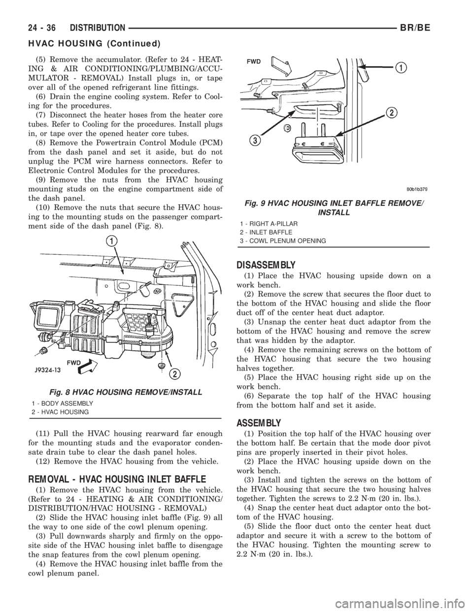
ment side of the dash panel (Fig. 8).
(11) Pull the HVAC housing rearward far enough
for the mounting studs and the evaporator conden-
sate drain tube to clear the dash panel holes.
(12) Remove the HVAC housing from the vehicle.
REMOVAL - HVAC HOUSING INLET BAFFLE
(1) Remove the HVAC housing from the vehicle.
(Refer to 24 - HEATING & AIR CONDITIONING/
DISTRIBUTION/HVAC HOUSING - REMOVAL)
(2) Slide the HVAC housing inlet baffle (Fig. 9) all
the way to one side of the cowl plenum opening.
(3)
Pull downwards sharply and firmly on the oppo-
site side of the HVAC housing inlet baffle to disengage
the snap features from the cowl plenum opening.
(4) Remove the HVAC housing inlet baffle from the
cowl plenum panel.
DISASSEMBLY
(1) Place the HVAC housing upside down on a
work bench.
(2) Remove the screw that secures the floor duct to
the bottom of the HVAC housing and slide the floor
duct off of the center heat duct adaptor.
(3) Unsnap the center heat duct adaptor from the
bottom of the HVAC housing and remove the screw
that was hidden by the adaptor.
(4) Remove the remaining screws on the bottom of
the HVAC housing that secure the two housing
halves together.
(5) Place the HVAC housing right side up on the
work bench.
(6) Separate the top half of the HVAC housing
from the bottom half and set it aside.
ASSEMBLY
(1) Position the top half of the HVAC housing over
the bottom half. Be certain that the mode door pivot
pins are properly inserted in their pivot holes.
(2) Place the HVAC housing upside down on the
work bench.
(3)
Install and tighten the screws on the bottom of
the HVAC housing that secure the two housing halves
together. Tighten the screws to 2.2 N´m (20 in. lbs.).
(4) Snap the center heat duct adaptor onto the bot-
tom of the HVAC housing.
(5) Slide the floor duct onto the center heat duct
adaptor and secure it with a screw to the bottom of
the HVAC housing. Tighten the mounting screw to
2.2 N´m (20 in. lbs.).
Fig. 8 HVAC HOUSING REMOVE/INSTALL
1 - BODY ASSEMBLY
2 - HVAC HOUSING
Fig. 9 HVAC HOUSING INLET BAFFLE REMOVE/
INSTALL
1 - RIGHT A-PILLAR
2 - INLET BAFFLE
3 - COWL PLENUM OPENING
24 - 36 DISTRIBUTIONBR/BE
HVAC HOUSING (Continued)
Page 2766 of 2889
INSTALLATION
(1) Position the HVAC housing to the dash panel.
Be certain that the evaporator condensate drain tube
and the housing mounting studs are inserted into
their correct mounting holes.
(2) Install the nuts that secure the HVAC housing
to the mounting studs on the passenger compartment
side of the dash panel. Tighten the nuts to 4.5 N´m
(40 in. lbs.).
(3)
Install and tighten the nuts onto the HVAC hous-
ing mounting studs on the engine compartment side of
the dash panel. Tighten the nuts to 7 N´m (60 in. lbs.).
(4) Unplug or remove the tape from the heater
core tubes. Connect the heater hoses to the heater
core tubes and fill the engine cooling system. Refer
Cooling for the procedures.
(5)
If the vehicle is not equipped with air condition-
ing, go to Step 10. If the vehicle is equipped with air
conditioning, install the accumulator. (Refer to 24 -
HEATING & AIR CONDITIONING/PLUMBING/ACCU-
MULATOR - INSTALLATION) Connect the accumulator
inlet tube coupler to the evaporator outlet tube. (Refer
to 24 - HEATING & AIR CONDITIONING/PLUMBING
- STANDARD PROCEDURE - A/C LINE COUPLERS)
(6)Unplug or remove the tape from the liquid line
and the evaporator inlet tube fittings. Connect the liq-
uid line coupler to the evaporator inlet tube. (Refer to
24 - HEATING & AIR CONDITIONING/PLUMBING -
STANDARD PROCEDURE - A/C LINE COUPLERS)
(7) Evacuate the refrigerant system. (Refer to 24 -
HEATING & AIR CONDITIONING/PLUMBING -
STANDARD PROCEDURE - REFRIGERANT SYS-
TEM EVACUATE)
(8) Charge the refrigerant system. (Refer to 24 -
HEATING & AIR CONDITIONING/PLUMBING -
STANDARD PROCEDURE - REFRIGERANT SYS-
TEM CHARGE)
(9) Reinstall the PCM to the dash panel. Refer to
Electronic Control Modules for the procedures.
(10) Reinstall the instrument panel in the vehicle.
Refer to Instrument Panel System for the procedures.
(11) Connect the battery negative cable.
(12) Start the engine and check for proper opera-
tion of the heating and air conditioning systems.
INSTALLATION - HVAC HOUSING INLET
BAFFLE
(1) Install the HVAC housing inlet baffle in the
cowl plenum panel.
(2) Slide the HVAC housing inlet baffle to engage
the snap features.
(3) Make certain that the snap features on each
side of the adapter are fully engaged with the sides
of the plenum panel opening. This must be a water
tight connection to prevent leaks.(4) Install the HVAC housing in the vehicle. (Refer
to 24 - HEATING & AIR CONDITIONING/DISTRI-
BUTION/HVAC HOUSING - INSTALLATION)
INSTRUMENT PANEL
DEMISTER DUCTS
REMOVAL
The defroster duct and the main demister duct are
a single molded plastic unit. The defroster outlet
grilles are heat-staked to the defroster outlets and
cannot be serviced separately. The demister tubes on
each end of the main demister duct are only serviced
in the instrument panel assembly. (Refer to 24 -
HEATING & AIR CONDITIONING/DISTRIBUTION/
DEFROSTER DUCTS - REMOVAL)
INSTRUMENT PANEL DUCTS
REMOVAL
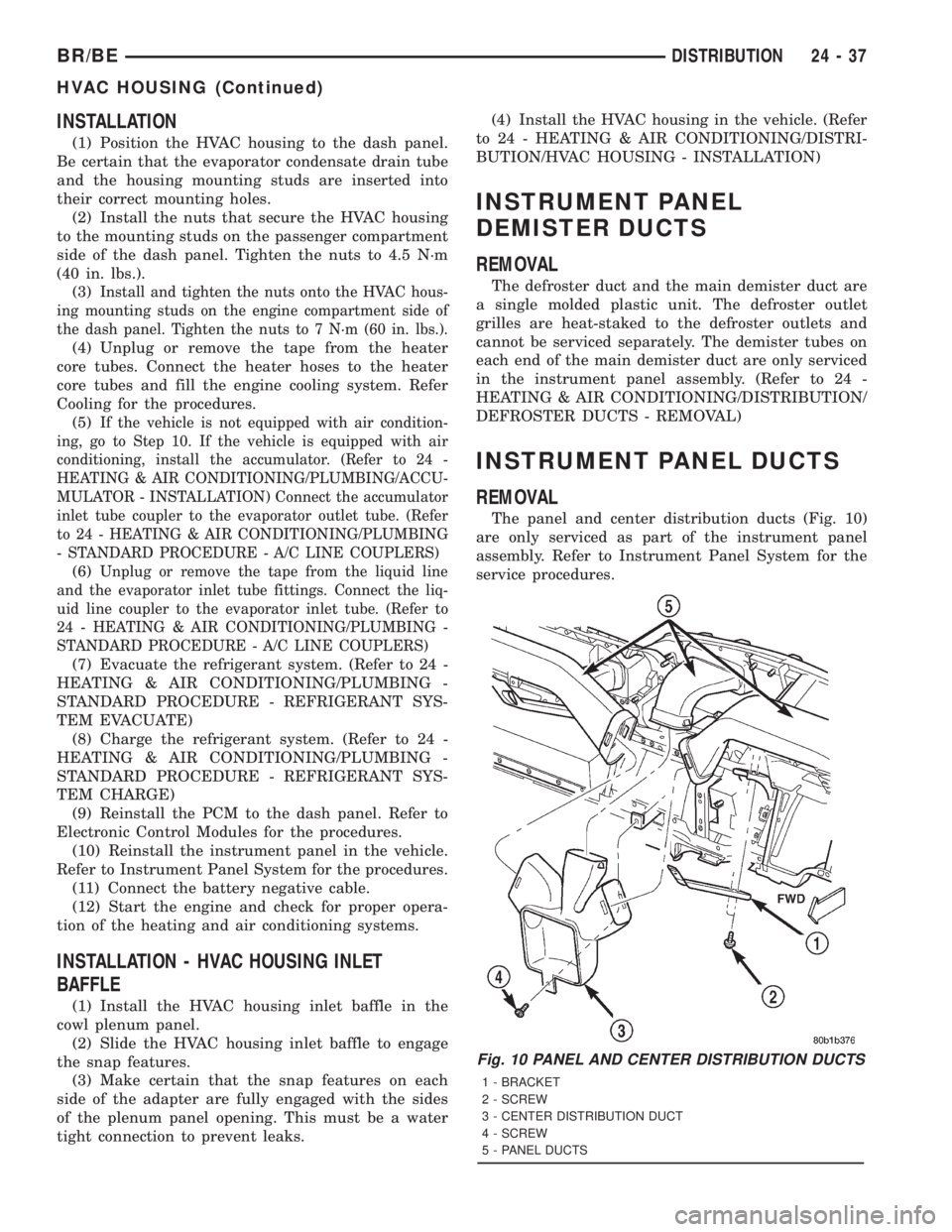
The panel and center distribution ducts (Fig. 10)
are only serviced as part of the instrument panel
assembly. Refer to Instrument Panel System for the
service procedures.
Fig. 10 PANEL AND CENTER DISTRIBUTION DUCTS
1 - BRACKET
2 - SCREW
3 - CENTER DISTRIBUTION DUCT
4 - SCREW
5 - PANEL DUCTS
BR/BEDISTRIBUTION 24 - 37
HVAC HOUSING (Continued)
Page 2769 of 2889
PLUMBING
TABLE OF CONTENTS
page page
PLUMBING
DESCRIPTION...........................40
OPERATION.............................41
WARNING..............................41
CAUTION...............................41
DIAGNOSIS AND TESTING.................43
REFRIGERANT SYSTEM LEAKS...........43
STANDARD PROCEDURE..................43
A/C LINE COUPLERS....................43
REFRIGERANT SYSTEM SERVICE
EQUIPMENT...........................44
REFRIGERANT RECOVERY...............45
REFRIGERANT SYSTEM EVACUATE........45
REFRIGERANT SYSTEM CHARGE.........46
SPECIFICATIONS........................46
A/C COMPRESSOR
DESCRIPTION...........................46
OPERATION.............................46
DIAGNOSIS AND TESTING.................46
A/C COMPRESSOR.....................46
REMOVAL..............................47
INSTALLATION...........................47
A/C CONDENSER
DESCRIPTION...........................48
OPERATION.............................48
REMOVAL..............................49
INSTALLATION...........................49
SUCTION AND DISCHARGE LINE
REMOVAL..............................50
INSTALLATION...........................51
LIQUID LINE
REMOVAL..............................52INSTALLATION...........................52
A/C EVAPORATOR
DESCRIPTION...........................52
OPERATION.............................53
REMOVAL..............................53
INSTALLATION...........................53
A/C ORIFICE TUBE
DESCRIPTION...........................53
OPERATION.............................53
DIAGNOSIS AND TESTING.................54
FIXED ORIFICE TUBE...................54
REMOVAL..............................54
ACCUMULATOR
DESCRIPTION...........................54
OPERATION.............................54
REMOVAL..............................54
INSTALLATION...........................55
HEATER CORE
DESCRIPTION...........................55
OPERATION.............................55
REMOVAL..............................56
INSTALLATION...........................56
REFRIGERANT
DESCRIPTION...........................56
OPERATION.............................56
REFRIGERANT OIL
DESCRIPTION...........................56
OPERATION.............................56
STANDARD PROCEDURE..................57
REFRIGERANT OIL LEVEL................57
PLUMBING
DESCRIPTION - A/C LINE COUPLERS
Spring-lock type refrigerant line couplers are used
to connect many of the refrigerant lines and other
components to the refrigerant system. These couplers
require a special tool for disengaging the two coupler
halves.
DESCRIPTION
The refrigerant lines and hoses are used to carry
the refrigerant between the various air conditioning
system components. A barrier hose design with a
nylon tube, which is sandwiched between rubber lay-
ers, is used for the R-134a air conditioning system onthis vehicle. This nylon tube helps to further contain
the R-134a refrigerant, which has a smaller molecu-
lar structure than R-12 refrigerant. The ends of the
refrigerant hoses are made from lightweight alumi-
num or steel, and commonly use braze-less fittings.
Any kinks or sharp bends in the refrigerant plumb-
ing will reduce the capacity of the entire air condi-
tioning system. Kinks and sharp bends reduce the
flow of refrigerant in the system. A good rule for the
flexible hose refrigerant lines is to keep the radius of
all bends at least ten times the diameter of the hose.
In addition, the flexible hose refrigerant lines should
be routed so they are at least 80 millimeters (3
inches) from the exhaust manifold.
24 - 40 PLUMBINGBR/BE
Page 2784 of 2889
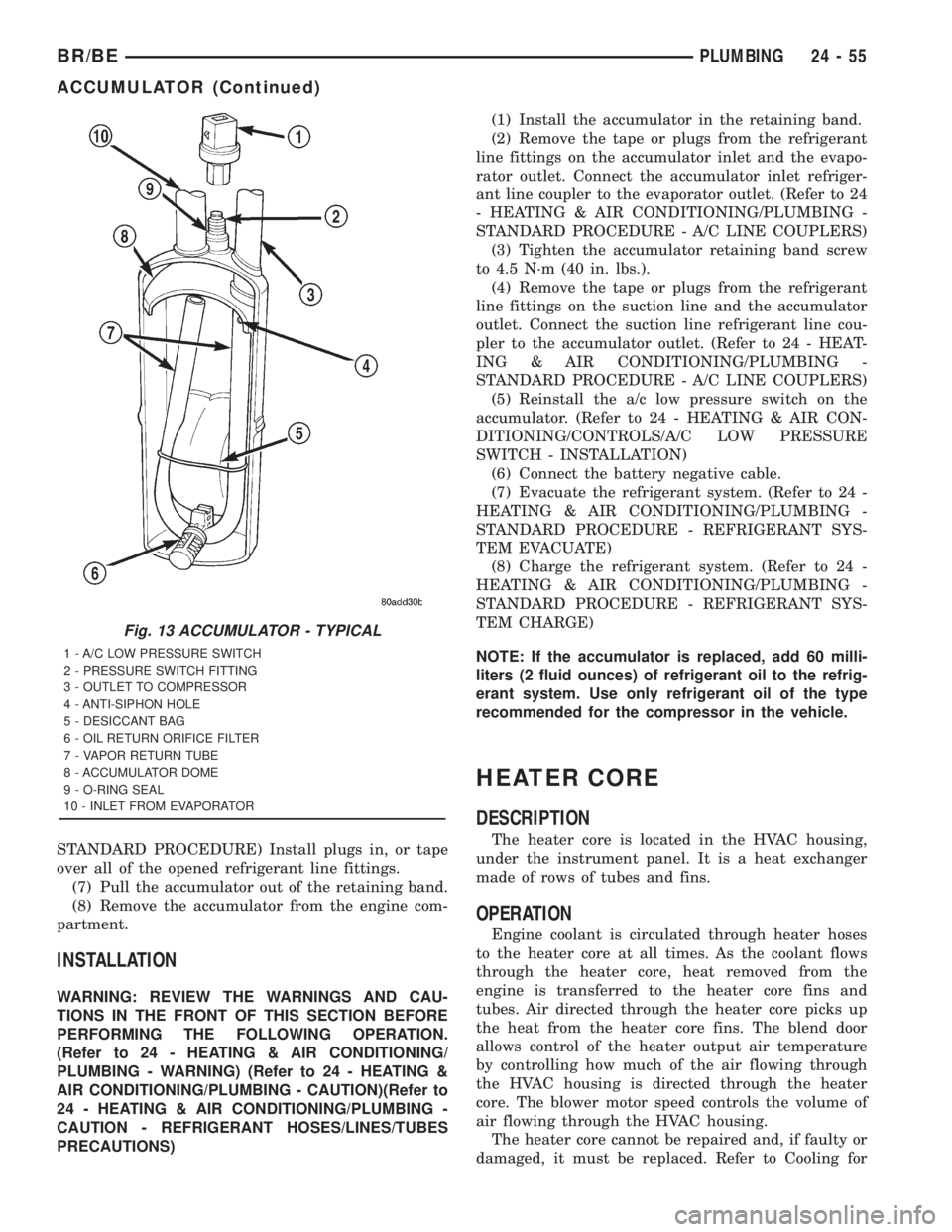
STANDARD PROCEDURE) Install plugs in, or tape
over all of the opened refrigerant line fittings.
(7) Pull the accumulator out of the retaining band.
(8) Remove the accumulator from the engine com-
partment.
INSTALLATION
WARNING: REVIEW THE WARNINGS AND CAU-
TIONS IN THE FRONT OF THIS SECTION BEFORE
PERFORMING THE FOLLOWING OPERATION.
(Refer to 24 - HEATING & AIR CONDITIONING/
PLUMBING - WARNING) (Refer to 24 - HEATING &
AIR CONDITIONING/PLUMBING - CAUTION)(Refer to
24 - HEATING & AIR CONDITIONING/PLUMBING -
CAUTION - REFRIGERANT HOSES/LINES/TUBES
PRECAUTIONS)(1) Install the accumulator in the retaining band.
(2) Remove the tape or plugs from the refrigerant
line fittings on the accumulator inlet and the evapo-
rator outlet. Connect the accumulator inlet refriger-
ant line coupler to the evaporator outlet. (Refer to 24
- HEATING & AIR CONDITIONING/PLUMBING -
STANDARD PROCEDURE - A/C LINE COUPLERS)
(3) Tighten the accumulator retaining band screw
to 4.5 N´m (40 in. lbs.).
(4) Remove the tape or plugs from the refrigerant
line fittings on the suction line and the accumulator
outlet. Connect the suction line refrigerant line cou-
pler to the accumulator outlet. (Refer to 24 - HEAT-
ING & AIR CONDITIONING/PLUMBING -
STANDARD PROCEDURE - A/C LINE COUPLERS)
(5) Reinstall the a/c low pressure switch on the
accumulator. (Refer to 24 - HEATING & AIR CON-
DITIONING/CONTROLS/A/C LOW PRESSURE
SWITCH - INSTALLATION)
(6) Connect the battery negative cable.
(7) Evacuate the refrigerant system. (Refer to 24 -
HEATING & AIR CONDITIONING/PLUMBING -
STANDARD PROCEDURE - REFRIGERANT SYS-
TEM EVACUATE)
(8) Charge the refrigerant system. (Refer to 24 -
HEATING & AIR CONDITIONING/PLUMBING -
STANDARD PROCEDURE - REFRIGERANT SYS-
TEM CHARGE)
NOTE: If the accumulator is replaced, add 60 milli-
liters (2 fluid ounces) of refrigerant oil to the refrig-
erant system. Use only refrigerant oil of the type
recommended for the compressor in the vehicle.
HEATER CORE
DESCRIPTION
The heater core is located in the HVAC housing,
under the instrument panel. It is a heat exchanger
made of rows of tubes and fins.
OPERATION
Engine coolant is circulated through heater hoses
to the heater core at all times. As the coolant flows
through the heater core, heat removed from the
engine is transferred to the heater core fins and
tubes. Air directed through the heater core picks up
the heat from the heater core fins. The blend door
allows control of the heater output air temperature
by controlling how much of the air flowing through
the HVAC housing is directed through the heater
core. The blower motor speed controls the volume of
air flowing through the HVAC housing.
The heater core cannot be repaired and, if faulty or
damaged, it must be replaced. Refer to Cooling for
Fig. 13 ACCUMULATOR - TYPICAL
1 - A/C LOW PRESSURE SWITCH
2 - PRESSURE SWITCH FITTING
3 - OUTLET TO COMPRESSOR
4 - ANTI-SIPHON HOLE
5 - DESICCANT BAG
6 - OIL RETURN ORIFICE FILTER
7 - VAPOR RETURN TUBE
8 - ACCUMULATOR DOME
9 - O-RING SEAL
10 - INLET FROM EVAPORATOR
BR/BEPLUMBING 24 - 55
ACCUMULATOR (Continued)
Page 2785 of 2889
more information on the engine cooling system, the
engine coolant and the heater hoses.
REMOVAL
(1) Remove the HVAC housing from the vehicle.
(Refer to 24 - HEATING & AIR CONDITIONING/
DISTRIBUTION/HVAC HOUSING - REMOVAL)
(2) Remove the screws and retainers that secure
the heater core to the HVAC housing.
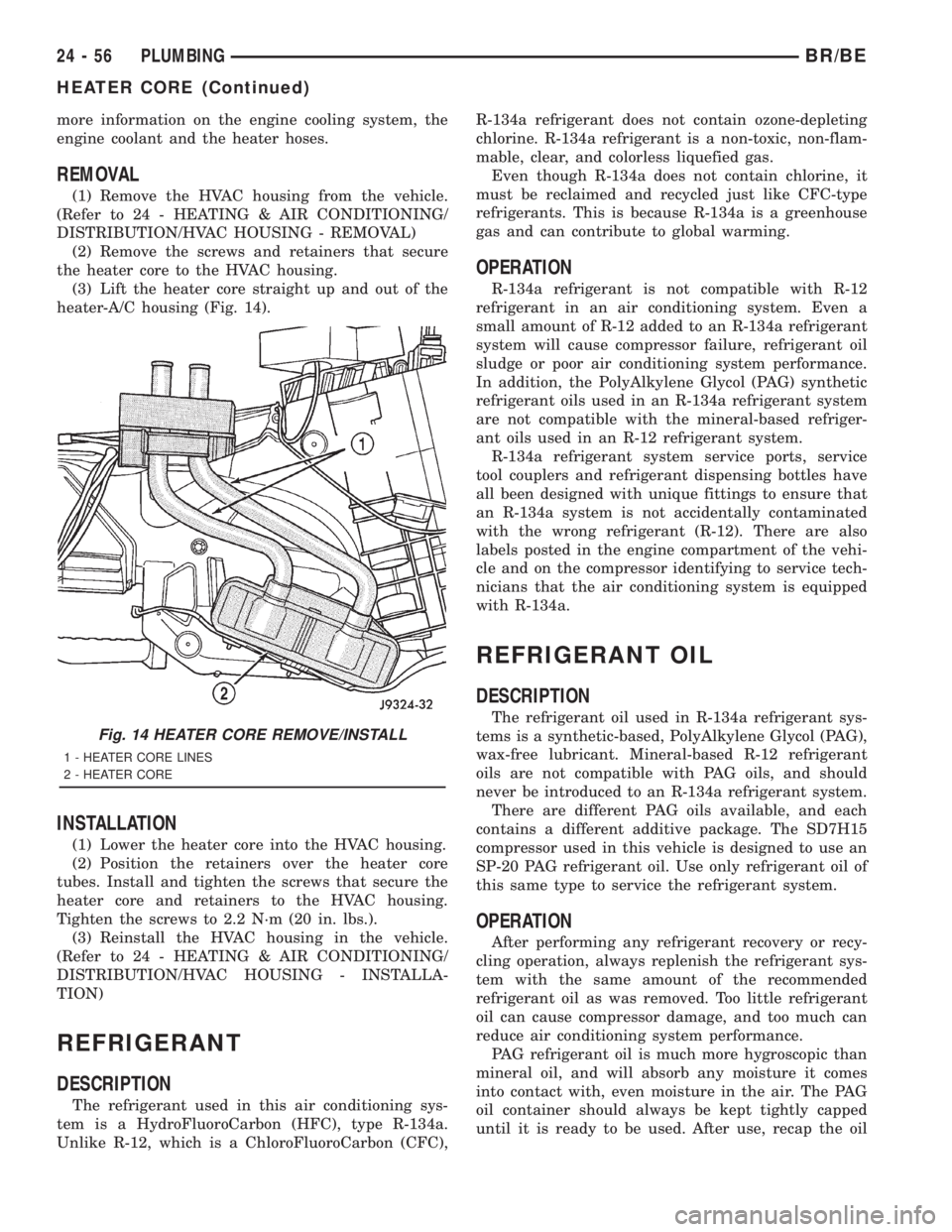
(3) Lift the heater core straight up and out of the
heater-A/C housing (Fig. 14).
INSTALLATION
(1) Lower the heater core into the HVAC housing.
(2) Position the retainers over the heater core
tubes. Install and tighten the screws that secure the
heater core and retainers to the HVAC housing.
Tighten the screws to 2.2 N´m (20 in. lbs.).
(3) Reinstall the HVAC housing in the vehicle.
(Refer to 24 - HEATING & AIR CONDITIONING/
DISTRIBUTION/HVAC HOUSING - INSTALLA-
TION)
REFRIGERANT
DESCRIPTION
The refrigerant used in this air conditioning sys-
tem is a HydroFluoroCarbon (HFC), type R-134a.
Unlike R-12, which is a ChloroFluoroCarbon (CFC),R-134a refrigerant does not contain ozone-depleting
chlorine. R-134a refrigerant is a non-toxic, non-flam-
mable, clear, and colorless liquefied gas.
Even though R-134a does not contain chlorine, it
must be reclaimed and recycled just like CFC-type
refrigerants. This is because R-134a is a greenhouse
gas and can contribute to global warming.
OPERATION
R-134a refrigerant is not compatible with R-12
refrigerant in an air conditioning system. Even a
small amount of R-12 added to an R-134a refrigerant
system will cause compressor failure, refrigerant oil
sludge or poor air conditioning system performance.
In addition, the PolyAlkylene Glycol (PAG) synthetic
refrigerant oils used in an R-134a refrigerant system
are not compatible with the mineral-based refriger-
ant oils used in an R-12 refrigerant system.
R-134a refrigerant system service ports, service
tool couplers and refrigerant dispensing bottles have
all been designed with unique fittings to ensure that
an R-134a system is not accidentally contaminated
with the wrong refrigerant (R-12). There are also
labels posted in the engine compartment of the vehi-
cle and on the compressor identifying to service tech-
nicians that the air conditioning system is equipped
with R-134a.
REFRIGERANT OIL
DESCRIPTION
The refrigerant oil used in R-134a refrigerant sys-
tems is a synthetic-based, PolyAlkylene Glycol (PAG),
wax-free lubricant. Mineral-based R-12 refrigerant
oils are not compatible with PAG oils, and should
never be introduced to an R-134a refrigerant system.
There are different PAG oils available, and each
contains a different additive package. The SD7H15
compressor used in this vehicle is designed to use an
SP-20 PAG refrigerant oil. Use only refrigerant oil of
this same type to service the refrigerant system.
OPERATION
After performing any refrigerant recovery or recy-
cling operation, always replenish the refrigerant sys-
tem with the same amount of the recommended
refrigerant oil as was removed. Too little refrigerant
oil can cause compressor damage, and too much can
reduce air conditioning system performance.
PAG refrigerant oil is much more hygroscopic than
mineral oil, and will absorb any moisture it comes
into contact with, even moisture in the air. The PAG
oil container should always be kept tightly capped
until it is ready to be used. After use, recap the oil
Fig. 14 HEATER CORE REMOVE/INSTALL
1 - HEATER CORE LINES
2 - HEATER CORE
24 - 56 PLUMBINGBR/BE
HEATER CORE (Continued)
Page 2789 of 2889
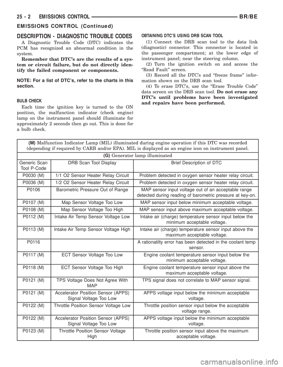
DESCRIPTION - DIAGNOSTIC TROUBLE CODES
A Diagnostic Trouble Code (DTC) indicates the
PCM has recognized an abnormal condition in the
system.
Remember that DTC's are the results of a sys-
tem or circuit failure, but do not directly iden-
tify the failed component or components.
NOTE: For a list of DTC's, refer to the charts in this
section.
BULB CHECK
Each time the ignition key is turned to the ON
position, the malfunction indicator (check engine)
lamp on the instrument panel should illuminate for
approximately 2 seconds then go out. This is done for
a bulb check.OBTAINING DTC'S USING DRB SCAN TOOL
(1) Connect the DRB scan tool to the data link
(diagnostic) connector. This connector is located in
the passenger compartment; at the lower edge of
instrument panel; near the steering column.
(2) Turn the ignition switch on and access the
ªRead Faultº screen.
(3) Record all the DTC's and ªfreeze frameº infor-
mation shown on the DRB scan tool.
(4) To erase DTC's, use the ªErase Trouble Codeº
data screen on the DRB scan tool.Do not erase any
DTC's until problems have been investigated
and repairs have been performed.
(M)Malfunction Indicator Lamp (MIL) illuminated during engine operation if this DTC was recorded
(depending if required by CARB and/or EPA). MIL is displayed as an engine icon on instrument panel.
(G)Generator lamp illuminated
Generic Scan
Tool P-CodeDRB Scan Tool Display Brief Description of DTC
P0030 (M) 1/1 O2 Sensor Heater Relay Circuit Problem detected in oxygen sensor heater relay circuit.
P0036 (M) 1/2 O2 Sensor Heater Relay Circuit Problem detected in oxygen sensor heater relay circuit.
P0106 Barometric Pressure Out of Range MAP sensor input voltage out of an acceptable range
detected during reading of barometric pressure at key-on.
P0107 (M) Map Sensor Voltage Too Low MAP sensor input below minimum acceptable voltage.
P0108 (M) Map Sensor Voltage Too High MAP sensor input above maximum acceptable voltage.
P0112 (M) Intake Air Temp Sensor Voltage Low Intake air (charge) temperature sensor input below the
minimum acceptable voltage.
P0113 (M) Intake Air Temp Sensor Voltage High Intake air (charge) temperature sensor input above the
maximum acceptable voltage.
P0116 A rationatilty error has been detected in the coolant temp
sensor.
P0117 (M) ECT Sensor Voltage Too Low Engine coolant temperature sensor input below the
minimum acceptable voltage.
P0118 (M) ECT Sensor Voltage Too High Engine coolant temperature sensor input above the
maximum acceptable voltage.
P0121 (M) TPS Voltage Does Not Agree With
MAPTPS signal does not correlate to MAP sensor signal.
P0121 (M) Accelerator Position Sensor (APPS)
Signal Voltage Too LowAPPS voltage input below the minimum acceptable
voltage.
P0122 (M) Throttle Position Sensor Voltage Low Throttle position sensor input below the acceptable
voltage range.
P0122 (M) Accelerator Position Sensor (APPS)
Signal Voltage Too LowAPPS voltage input below the minimum acceptable
voltage.
P0123 (M) Throttle Position Sensor Voltage
HighThrottle position sensor input above the maximum
acceptable voltage.
25 - 2 EMISSIONS CONTROLBR/BE
EMISSIONS CONTROL (Continued)
Page 2790 of 2889
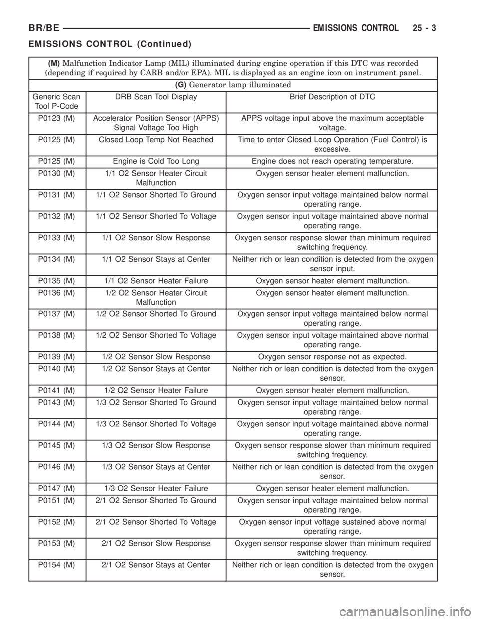
(M)Malfunction Indicator Lamp (MIL) illuminated during engine operation if this DTC was recorded
(depending if required by CARB and/or EPA). MIL is displayed as an engine icon on instrument panel.
(G)Generator lamp illuminated
Generic Scan
Tool P-CodeDRB Scan Tool Display Brief Description of DTC
P0123 (M) Accelerator Position Sensor (APPS)
Signal Voltage Too HighAPPS voltage input above the maximum acceptable
voltage.
P0125 (M) Closed Loop Temp Not Reached Time to enter Closed Loop Operation (Fuel Control) is
excessive.
P0125 (M) Engine is Cold Too Long Engine does not reach operating temperature.
P0130 (M) 1/1 O2 Sensor Heater Circuit
MalfunctionOxygen sensor heater element malfunction.
P0131 (M) 1/1 O2 Sensor Shorted To Ground Oxygen sensor input voltage maintained below normal
operating range.
P0132 (M) 1/1 O2 Sensor Shorted To Voltage Oxygen sensor input voltage maintained above normal
operating range.
P0133 (M) 1/1 O2 Sensor Slow Response Oxygen sensor response slower than minimum required
switching frequency.
P0134 (M) 1/1 O2 Sensor Stays at Center Neither rich or lean condition is detected from the oxygen
sensor input.
P0135 (M) 1/1 O2 Sensor Heater Failure Oxygen sensor heater element malfunction.
P0136 (M) 1/2 O2 Sensor Heater Circuit
MalfunctionOxygen sensor heater element malfunction.
P0137 (M) 1/2 O2 Sensor Shorted To Ground Oxygen sensor input voltage maintained below normal
operating range.
P0138 (M) 1/2 O2 Sensor Shorted To Voltage Oxygen sensor input voltage maintained above normal
operating range.
P0139 (M) 1/2 O2 Sensor Slow Response Oxygen sensor response not as expected.
P0140 (M) 1/2 O2 Sensor Stays at Center Neither rich or lean condition is detected from the oxygen
sensor.
P0141 (M) 1/2 O2 Sensor Heater Failure Oxygen sensor heater element malfunction.
P0143 (M) 1/3 O2 Sensor Shorted To Ground Oxygen sensor input voltage maintained below normal
operating range.
P0144 (M) 1/3 O2 Sensor Shorted To Voltage Oxygen sensor input voltage maintained above normal
operating range.
P0145 (M) 1/3 O2 Sensor Slow Response Oxygen sensor response slower than minimum required
switching frequency.
P0146 (M) 1/3 O2 Sensor Stays at Center Neither rich or lean condition is detected from the oxygen
sensor.
P0147 (M) 1/3 O2 Sensor Heater Failure Oxygen sensor heater element malfunction.
P0151 (M) 2/1 O2 Sensor Shorted To Ground Oxygen sensor input voltage maintained below normal
operating range.
P0152 (M) 2/1 O2 Sensor Shorted To Voltage Oxygen sensor input voltage sustained above normal
operating range.
P0153 (M) 2/1 O2 Sensor Slow Response Oxygen sensor response slower than minimum required
switching frequency.
P0154 (M) 2/1 O2 Sensor Stays at Center Neither rich or lean condition is detected from the oxygen
sensor.
BR/BEEMISSIONS CONTROL 25 - 3
EMISSIONS CONTROL (Continued)