2001 DODGE RAM transmission oil
[x] Cancel search: transmission oilPage 1673 of 2889
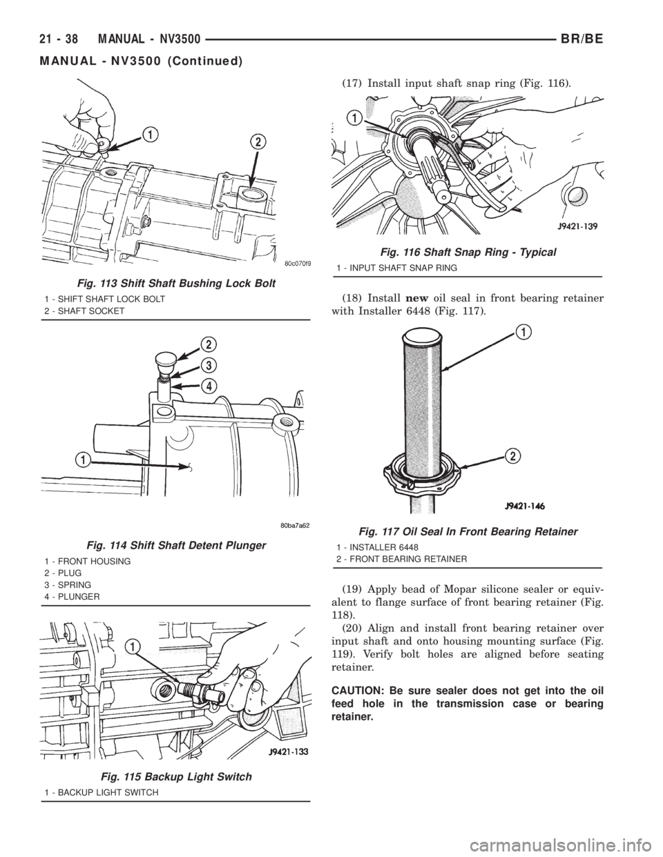
(17) Install input shaft snap ring (Fig. 116).
(18) Installnewoil seal in front bearing retainer
with Installer 6448 (Fig. 117).
(19) Apply bead of Mopar silicone sealer or equiv-
alent to flange surface of front bearing retainer (Fig.
118).
(20) Align and install front bearing retainer over
input shaft and onto housing mounting surface (Fig.
119). Verify bolt holes are aligned before seating
retainer.
CAUTION: Be sure sealer does not get into the oil
feed hole in the transmission case or bearing
retainer.
Fig. 113 Shift Shaft Bushing Lock Bolt
1 - SHIFT SHAFT LOCK BOLT
2 - SHAFT SOCKET
Fig. 114 Shift Shaft Detent Plunger
1 - FRONT HOUSING
2 - PLUG
3 - SPRING
4 - PLUNGER
Fig. 115 Backup Light Switch
1 - BACKUP LIGHT SWITCH
Fig. 116 Shaft Snap Ring - Typical
1 - INPUT SHAFT SNAP RING
Fig. 117 Oil Seal In Front Bearing Retainer
1 - INSTALLER 6448
2 - FRONT BEARING RETAINER
21 - 38 MANUAL - NV3500BR/BE
MANUAL - NV3500 (Continued)
Page 1674 of 2889
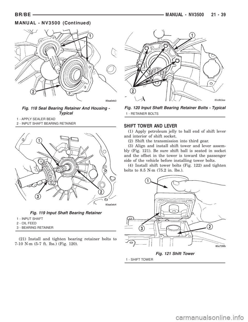
(21) Install and tighten bearing retainer bolts to
7-10 N´m (5-7 ft. lbs.) (Fig. 120).
SHIFT TOWER AND LEVER
(1) Apply petroleum jelly to ball end of shift lever
and interior of shift socket.
(2) Shift the transmission into third gear.
(3) Align and install shift tower and lever assem-
bly (Fig. 121). Be sure shift ball is seated in socket
and the offset in the tower is toward the passenger
side of the vehicle before installing tower bolts.
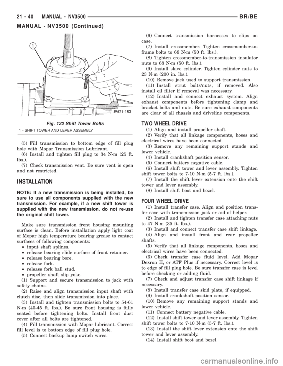
(4) Install shift tower bolts (Fig. 122) and tighten
bolts to 8.5 N´m (75.2 in. lbs.).
Fig. 118 Seal Bearing Retainer And Housing -
Typical
1 - APPLY SEALER BEAD
2 - INPUT SHAFT BEARING RETAINER
Fig. 119 Input Shaft Bearing Retainer
1 - INPUT SHAFT
2 - OIL FEED
3 - BEARING RETAINER
Fig. 120 Input Shaft Bearing Retainer Bolts - Typical
1 - RETAINER BOLTS
Fig. 121 Shift Tower
1 - SHIFT TOWER
BR/BEMANUAL - NV3500 21 - 39
MANUAL - NV3500 (Continued)
Page 1675 of 2889
(5) Fill transmission to bottom edge of fill plug
hole with Mopar Transmission Lubricant.
(6) Install and tighten fill plug to 34 N´m (25 ft.
lbs.).
(7) Check transmission vent. Be sure vent is open
and not restricted.
INSTALLATION
NOTE: If a new transmission is being installed, be
sure to use all components supplied with the new
transmission. For example, if a new shift tower is
supplied with the new transmission, do not re-use
the original shift tower.
Make sure transmission front housing mounting
surface is clean. Before installation apply light coat
of Mopar high temperature bearing grease to contact
surfaces of following components:
²input shaft splines.
²release bearing slide surface of front retainer.
²release bearing bore.
²release fork.
²release fork ball stud.
²propeller shaft slip yoke.
(1) Support and secure transmission to jack with
safety chains.
(2) Raise and align transmission input shaft with
clutch disc, then slide transmission into place.
(3) Install and tighten transmission bolts to 54-61
N´m (40-45 ft. lbs.). Be sure front housing is fully
seated before tightening bolts. Install front dust
cover after all bolts are tightened.
(4) Fill transmission with Mopar lubricant. Correct
fill level is to bottom edge of fill plug hole.
(5) Connect backup lamp switch wires.(6) Connect transmission harnesses to clips on
case.
(7) Install crossmember. Tighten crossmember-to-
frame bolts to 68 N´m (50 ft. lbs.).
(8) Tighten crossmember-to-transmission insulator
nuts to 68 N´m (50 ft. lbs.).
(9) Install slave cylinder. Tighten cylinder nuts to
23 N´m (200 in. lbs.).
(10) Remove jack used to support transmission.
(11) Install strut bolts/nuts, if removed. Also
install oil filter if removal was necessary.
(12) Install and connect exhaust system. Align
exhaust components before tightening clamp and
bracket bolts and nuts. Be sure exhaust components
are clear of all chassis and driveline components.
TWO WHEEL DRIVE
(1) Align and install propeller shaft.
(2) Verify that all linkage components, hoses and
electrical wires have been connected.
(3) Remove any remaining support stands and
lower vehicle.
(4) Install crankshaft position sensor.
(5) Connect battery negative cable.
(6) Install shift tower and lever assembly. Tighten
shift tower bolts to 7-10 N´m (5-7 ft. lbs.).
(7) Install the shift lever extension onto the shift
tower and lever assembly.
(8) Install shift boot and bezel.
FOUR WHEEL DRIVE
(1) Install transfer case. Align and position trans-
fer case with transmission jack or aid of helper.
(2) Install and tighten transfer case attaching nuts
to 47 N´m (35 ft. lbs.).
(3) Install and connect transfer case shift linkage.
(4) Align and install front and rear propeller
shafts.
(5) Verify that all linkage components, hoses and
electrical wires have been connected.
(6) Check transfer case fluid level. Add Mopar
Dexron II, or ATF Plus if necessary. Correct level is
to edge of fill plug hole. Be sure transfer case is level
before checking or adding fluid.
(7) Check and adjust transfer case shift linkage if
necessary.
(8) Install transfer case skid plate, if equipped.
(9) Install crankshaft position sensor.
(10) Remove any remaining support stands and
lower vehicle.
(11) Connect battery negative cable.
(12) Install shift tower and lever assembly. Tighten
shift tower bolts to 7-10 N´m (5-7 ft. lbs.).
(13) Install the shift lever extension onto the shift
tower and lever assembly.
(14) Install shift boot and bezel.
Fig. 122 Shift Tower Bolts
1 - SHIFT TOWER AND LEVER ASSEMBLY
21 - 40 MANUAL - NV3500BR/BE
MANUAL - NV3500 (Continued)
Page 1681 of 2889
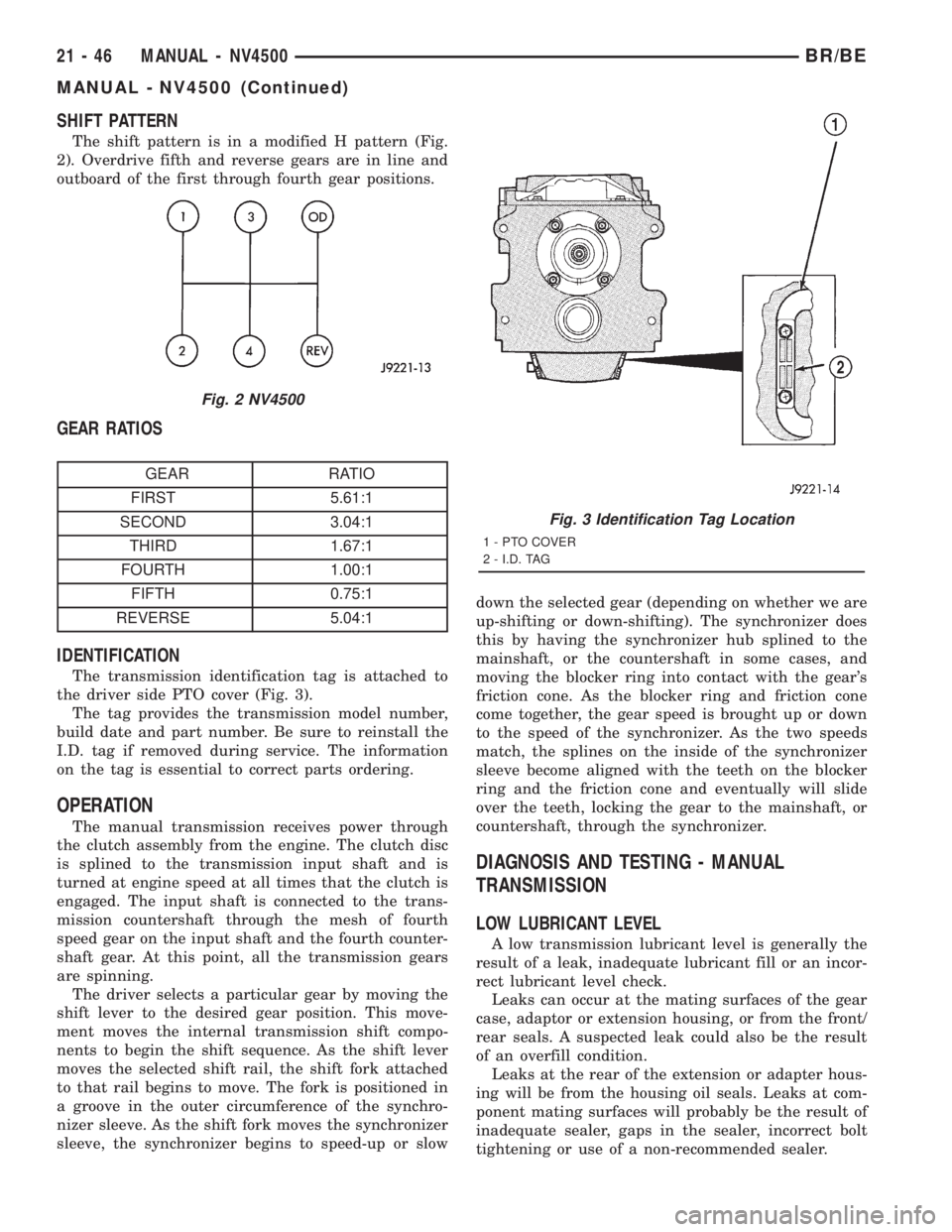
SHIFT PATTERN
The shift pattern is in a modified H pattern (Fig.
2). Overdrive fifth and reverse gears are in line and
outboard of the first through fourth gear positions.
GEAR RATIOS
GEAR RATIO
FIRST 5.61:1
SECOND 3.04:1
THIRD 1.67:1
FOURTH 1.00:1
FIFTH 0.75:1
REVERSE 5.04:1
IDENTIFICATION
The transmission identification tag is attached to
the driver side PTO cover (Fig. 3).
The tag provides the transmission model number,
build date and part number. Be sure to reinstall the
I.D. tag if removed during service. The information
on the tag is essential to correct parts ordering.
OPERATION
The manual transmission receives power through
the clutch assembly from the engine. The clutch disc
is splined to the transmission input shaft and is
turned at engine speed at all times that the clutch is
engaged. The input shaft is connected to the trans-
mission countershaft through the mesh of fourth
speed gear on the input shaft and the fourth counter-
shaft gear. At this point, all the transmission gears
are spinning.
The driver selects a particular gear by moving the
shift lever to the desired gear position. This move-
ment moves the internal transmission shift compo-
nents to begin the shift sequence. As the shift lever
moves the selected shift rail, the shift fork attached
to that rail begins to move. The fork is positioned in
a groove in the outer circumference of the synchro-
nizer sleeve. As the shift fork moves the synchronizer
sleeve, the synchronizer begins to speed-up or slowdown the selected gear (depending on whether we are
up-shifting or down-shifting). The synchronizer does
this by having the synchronizer hub splined to the
mainshaft, or the countershaft in some cases, and
moving the blocker ring into contact with the gear's
friction cone. As the blocker ring and friction cone
come together, the gear speed is brought up or down
to the speed of the synchronizer. As the two speeds
match, the splines on the inside of the synchronizer
sleeve become aligned with the teeth on the blocker
ring and the friction cone and eventually will slide
over the teeth, locking the gear to the mainshaft, or
countershaft, through the synchronizer.
DIAGNOSIS AND TESTING - MANUAL
TRANSMISSION
LOW LUBRICANT LEVEL
A low transmission lubricant level is generally the
result of a leak, inadequate lubricant fill or an incor-
rect lubricant level check.
Leaks can occur at the mating surfaces of the gear
case, adaptor or extension housing, or from the front/
rear seals. A suspected leak could also be the result
of an overfill condition.
Leaks at the rear of the extension or adapter hous-
ing will be from the housing oil seals. Leaks at com-
ponent mating surfaces will probably be the result of
inadequate sealer, gaps in the sealer, incorrect bolt
tightening or use of a non-recommended sealer.
Fig. 2 NV4500
Fig. 3 Identification Tag Location
1 - PTO COVER
2 - I.D. TAG
21 - 46 MANUAL - NV4500BR/BE
MANUAL - NV4500 (Continued)
Page 1699 of 2889
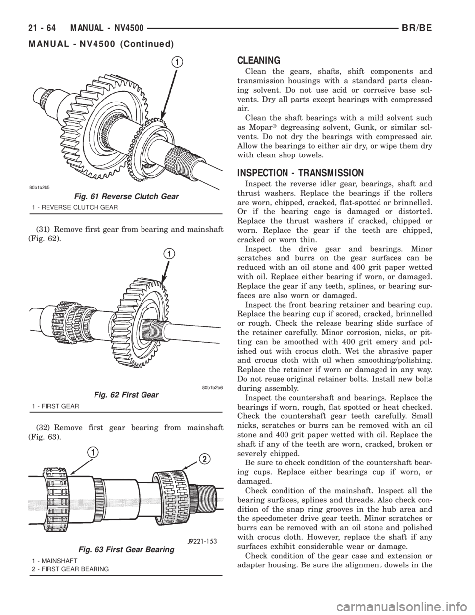
(31) Remove first gear from bearing and mainshaft
(Fig. 62).
(32) Remove first gear bearing from mainshaft
(Fig. 63).
CLEANING
Clean the gears, shafts, shift components and
transmission housings with a standard parts clean-
ing solvent. Do not use acid or corrosive base sol-
vents. Dry all parts except bearings with compressed
air.
Clean the shaft bearings with a mild solvent such
as Mopartdegreasing solvent, Gunk, or similar sol-
vents. Do not dry the bearings with compressed air.
Allow the bearings to either air dry, or wipe them dry
with clean shop towels.
INSPECTION - TRANSMISSION
Inspect the reverse idler gear, bearings, shaft and
thrust washers. Replace the bearings if the rollers
are worn, chipped, cracked, flat-spotted or brinnelled.
Or if the bearing cage is damaged or distorted.
Replace the thrust washers if cracked, chipped or
worn. Replace the gear if the teeth are chipped,
cracked or worn thin.
Inspect the drive gear and bearings. Minor
scratches and burrs on the gear surfaces can be
reduced with an oil stone and 400 grit paper wetted
with oil. Replace either bearing if worn, or damaged.
Replace the gear if any teeth, splines, or bearing sur-
faces are also worn or damaged.
Inspect the front bearing retainer and bearing cup.
Replace the bearing cup if scored, cracked, brinnelled
or rough. Check the release bearing slide surface of
the retainer carefully. Minor corrosion, nicks, or pit-
ting can be smoothed with 400 grit emery and pol-
ished out with crocus cloth. Wet the abrasive paper
and crocus cloth with oil when smoothing/polishing.
Replace the retainer if worn or damaged in any way.
Do not reuse original retainer bolts. Install new bolts
during assembly.
Inspect the countershaft and bearings. Replace the
bearings if worn, rough, flat spotted or heat checked.
Check the countershaft gear teeth carefully. Small
nicks, scratches or burrs can be removed with an oil
stone and 400 grit paper wetted with oil. Replace the
shaft if any of the teeth are worn, cracked, broken or
severely chipped.
Be sure to check condition of the countershaft bear-
ing cups. Replace either bearings cup if worn, or
damaged.
Check condition of the mainshaft. Inspect all the
bearing surfaces, splines and threads. Also check con-
dition of the snap ring grooves in the hub area and
the speedometer drive gear teeth. Minor scratches or
burrs can be removed with an oil stone and polished
with crocus cloth. However, replace the shaft if any
surfaces exhibit considerable wear or damage.
Check condition of the gear case and extension or
adapter housing. Be sure the alignment dowels in the
Fig. 61 Reverse Clutch Gear
1 - REVERSE CLUTCH GEAR
Fig. 62 First Gear
1 - FIRST GEAR
Fig. 63 First Gear Bearing
1 - MAINSHAFT
2 - FIRST GEAR BEARING
21 - 64 MANUAL - NV4500BR/BE
MANUAL - NV4500 (Continued)
Page 1700 of 2889
case top surface and in the housing/adapter are tight
and in good condition.
Run a tap through the gear case bolt holes if the
threads need minor cleanup. Helicoil inserts can be
used to repair seriously damaged threaded holes if
necessary.
Be sure all case and housing/adapter sealing and
mating surfaces are free of burrs and nicks. This is
especially important as gaskets are not used in the
transmission. Minor nicks and scratches on the seal-
ing surfaces can be dressed off with a fine tooth file
or oil stone.
Replace the gear case or housing/adapter if cracked
or broken. Do not attempt to repair this type of dam-
age by welding or brazing.
Check condition of the countershaft fifth gear com-
ponents. This includes the shift lug and rail located
in the gear case and the rail bushings.
Inspect the gear and hub assembly. Minor burrs
can be cleaned up with an oil stone. However, the
gear and hub assembly should be replaced if the
teeth or splines are excessively worn, or damaged.
The synchro sleeve should also be replaced if worn or
damaged in any way. Do not reuse synchro struts
that are worn or springs that are collapsed or
severely distorted. Replace worn distorted synchro
parts to avoid shift problems after assembly and
installation.
The shift fork should be inspected for evidence of
wear and distortion. Check fit of the sleeve in the
fork to be sure the two parts fit and work smoothly.
Replace the fork if the roll pin holes are worn over-
size or damaged. Do not attempt to salvage a worn
fork. It will cause shift problems later on. Replace
shift fork roll pins if necessary or if doubt exists
about their condition.
The bearings should be examined carefully for
wear, roughness, flat spots, pitting or other damage.
Replace the bearings if necessary.
Inspect the blocker ring and clutch gear. replace
either part if worn or damaged in any way. Also be
sure replacement parts fit properly before proceeding
with assembly.
Examine the 1-2 synchro hub and sleeve for wear
or damage. Replace sleeve and hub if the splines are
worn, chipped or damaged.
Replace the synchro struts if worn, or chipped. Also
replace the springs if collapsed, distorted or broken.
Inspect the mainshaft geartrain components.
Check teeth on all gears, hubs, clutch gears, stop
rings and clutch rings. The teeth must be in good
condition and not worn, cracked or chipped. Replace
any component that exhibits wear or damage.
Examine the synchro stop rings, clutch rings and
clutch gears. Replace any part that exhibits wear,distortion or damage. Replace the clutch rings if the
friction material is burned, flaking off or worn.
Inspect all of the thrust washers and locating pins.
Replace the pins if bent or worn. Replace the wash-
ers if worn or the locating pin notches are distorted.
Check condition of the synchro struts and springs.
Replace these parts if worn, cracked or distorted.
ASSEMBLY
NOTE: Gaskets are not used in the NV4500 trans-
mission. Use MoparTSilicone Sealer or equivalent
on all gear case and extension housing sealing sur-
faces.
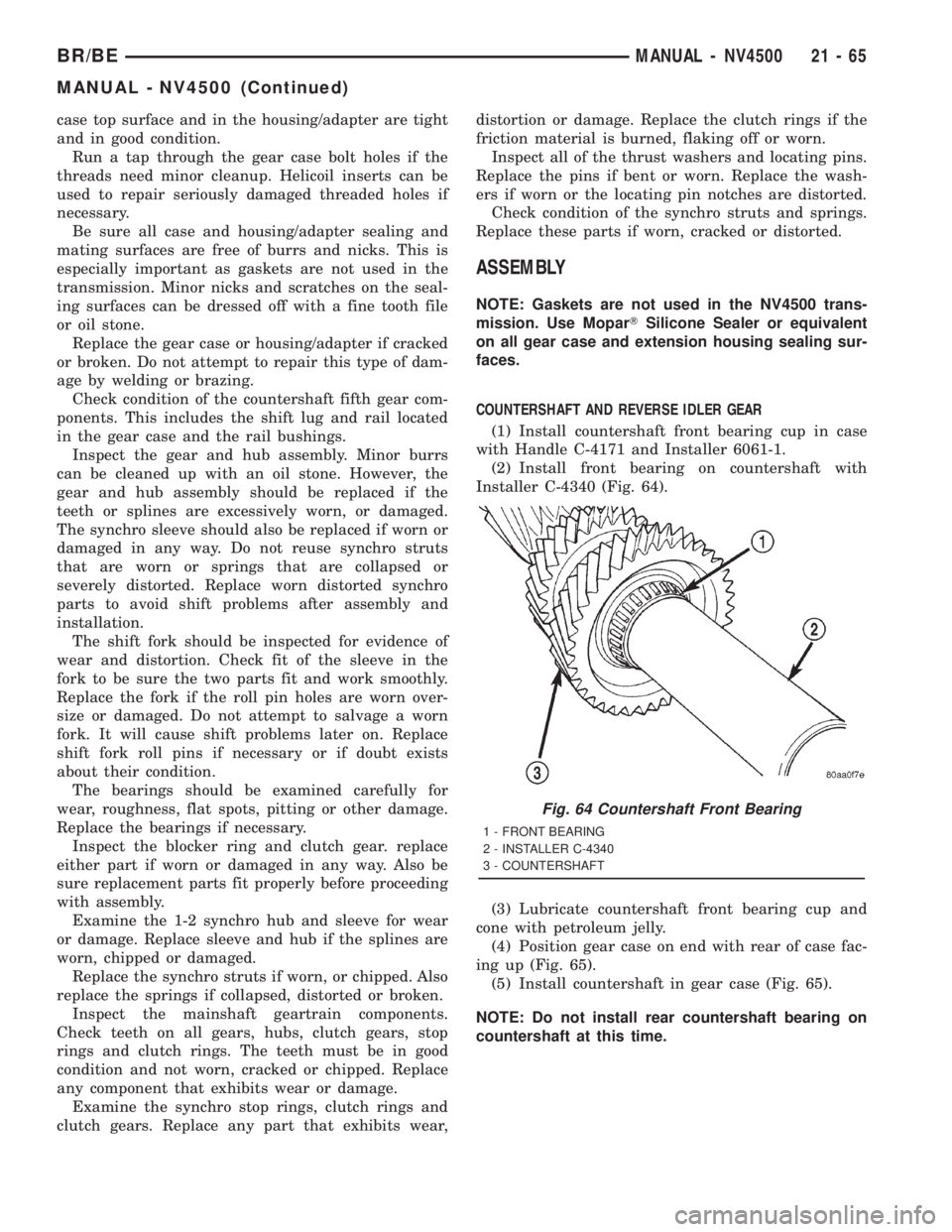
COUNTERSHAFT AND REVERSE IDLER GEAR
(1) Install countershaft front bearing cup in case
with Handle C-4171 and Installer 6061-1.
(2) Install front bearing on countershaft with
Installer C-4340 (Fig. 64).
(3) Lubricate countershaft front bearing cup and
cone with petroleum jelly.
(4) Position gear case on end with rear of case fac-
ing up (Fig. 65).
(5) Install countershaft in gear case (Fig. 65).
NOTE: Do not install rear countershaft bearing on
countershaft at this time.
Fig. 64 Countershaft Front Bearing
1 - FRONT BEARING
2 - INSTALLER C-4340
3 - COUNTERSHAFT
BR/BEMANUAL - NV4500 21 - 65
MANUAL - NV4500 (Continued)
Page 1711 of 2889
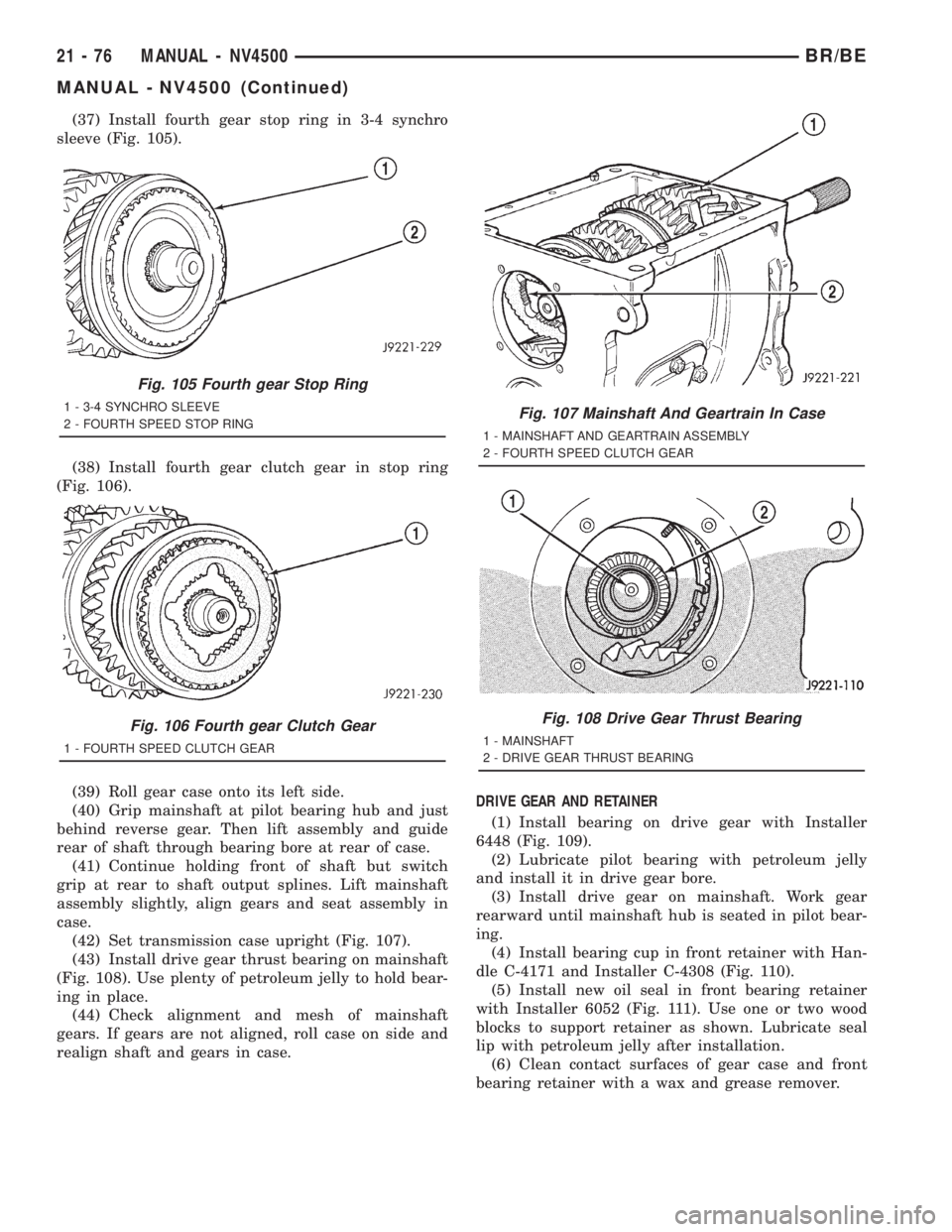
(37) Install fourth gear stop ring in 3-4 synchro
sleeve (Fig. 105).
(38) Install fourth gear clutch gear in stop ring
(Fig. 106).
(39) Roll gear case onto its left side.
(40) Grip mainshaft at pilot bearing hub and just
behind reverse gear. Then lift assembly and guide
rear of shaft through bearing bore at rear of case.
(41) Continue holding front of shaft but switch
grip at rear to shaft output splines. Lift mainshaft
assembly slightly, align gears and seat assembly in
case.
(42) Set transmission case upright (Fig. 107).
(43) Install drive gear thrust bearing on mainshaft
(Fig. 108). Use plenty of petroleum jelly to hold bear-
ing in place.
(44) Check alignment and mesh of mainshaft
gears. If gears are not aligned, roll case on side and
realign shaft and gears in case.DRIVE GEAR AND RETAINER
(1) Install bearing on drive gear with Installer
6448 (Fig. 109).
(2) Lubricate pilot bearing with petroleum jelly
and install it in drive gear bore.
(3) Install drive gear on mainshaft. Work gear
rearward until mainshaft hub is seated in pilot bear-
ing.
(4) Install bearing cup in front retainer with Han-
dle C-4171 and Installer C-4308 (Fig. 110).
(5) Install new oil seal in front bearing retainer
with Installer 6052 (Fig. 111). Use one or two wood
blocks to support retainer as shown. Lubricate seal
lip with petroleum jelly after installation.
(6) Clean contact surfaces of gear case and front
bearing retainer with a wax and grease remover.
Fig. 105 Fourth gear Stop Ring
1 - 3-4 SYNCHRO SLEEVE
2 - FOURTH SPEED STOP RING
Fig. 106 Fourth gear Clutch Gear
1 - FOURTH SPEED CLUTCH GEAR
Fig. 107 Mainshaft And Geartrain In Case
1 - MAINSHAFT AND GEARTRAIN ASSEMBLY
2 - FOURTH SPEED CLUTCH GEAR
Fig. 108 Drive Gear Thrust Bearing
1 - MAINSHAFT
2 - DRIVE GEAR THRUST BEARING
21 - 76 MANUAL - NV4500BR/BE
MANUAL - NV4500 (Continued)
Page 1713 of 2889
MAINSHAFT END PLAY
(1) Install mainshaft rear bearing cup in case and
over bearing. Tap bearing cup into place with plastic
mallet.
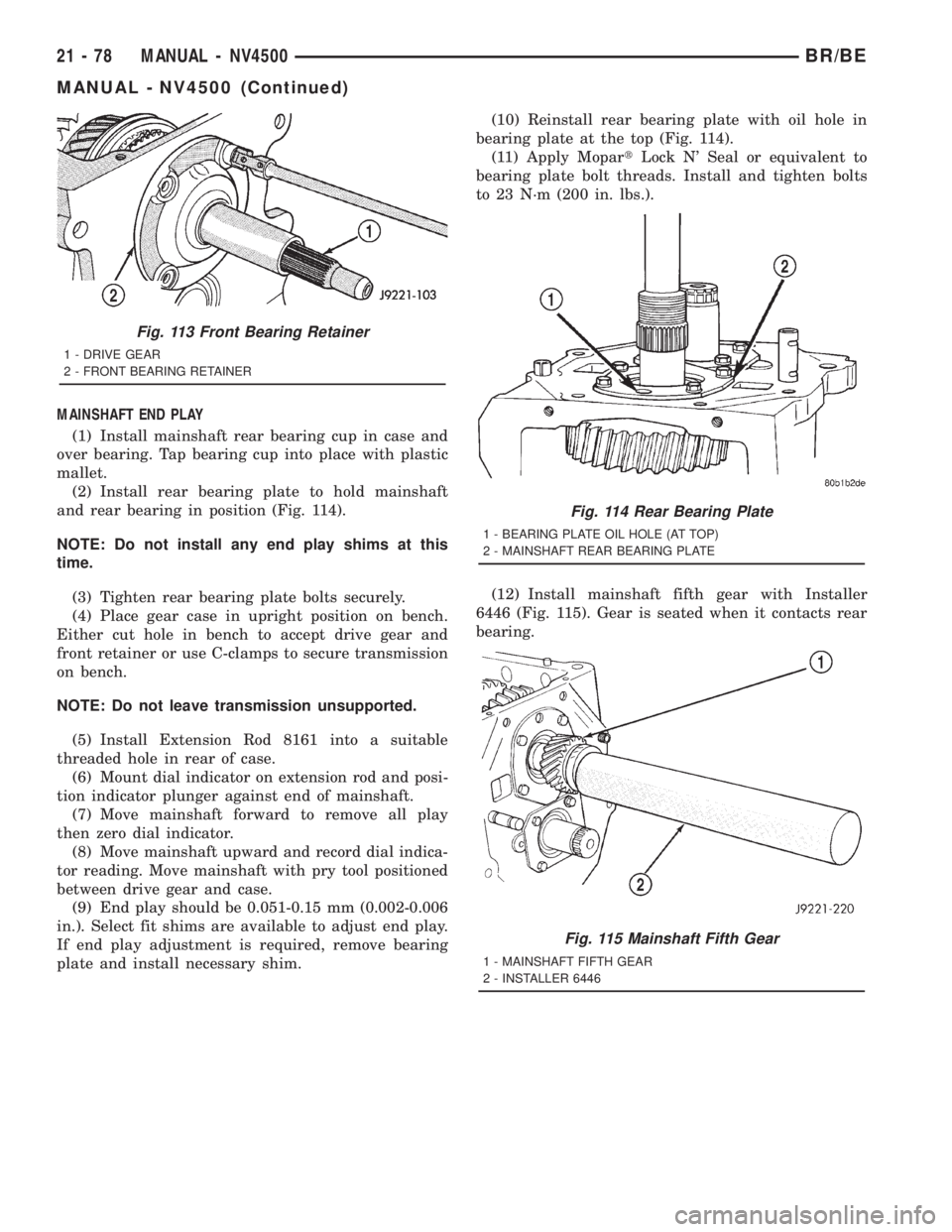
(2) Install rear bearing plate to hold mainshaft
and rear bearing in position (Fig. 114).
NOTE: Do not install any end play shims at this
time.
(3) Tighten rear bearing plate bolts securely.
(4) Place gear case in upright position on bench.
Either cut hole in bench to accept drive gear and
front retainer or use C-clamps to secure transmission
on bench.
NOTE: Do not leave transmission unsupported.
(5) Install Extension Rod 8161 into a suitable
threaded hole in rear of case.
(6) Mount dial indicator on extension rod and posi-
tion indicator plunger against end of mainshaft.
(7) Move mainshaft forward to remove all play
then zero dial indicator.
(8) Move mainshaft upward and record dial indica-
tor reading. Move mainshaft with pry tool positioned
between drive gear and case.
(9) End play should be 0.051-0.15 mm (0.002-0.006
in.). Select fit shims are available to adjust end play.
If end play adjustment is required, remove bearing
plate and install necessary shim.(10) Reinstall rear bearing plate with oil hole in
bearing plate at the top (Fig. 114).
(11) Apply MopartLock N' Seal or equivalent to
bearing plate bolt threads. Install and tighten bolts
to 23 N´m (200 in. lbs.).
(12) Install mainshaft fifth gear with Installer
6446 (Fig. 115). Gear is seated when it contacts rear
bearing.
Fig. 113 Front Bearing Retainer
1 - DRIVE GEAR
2 - FRONT BEARING RETAINER
Fig. 114 Rear Bearing Plate
1 - BEARING PLATE OIL HOLE (AT TOP)
2 - MAINSHAFT REAR BEARING PLATE
Fig. 115 Mainshaft Fifth Gear
1 - MAINSHAFT FIFTH GEAR
2 - INSTALLER 6446
21 - 78 MANUAL - NV4500BR/BE
MANUAL - NV4500 (Continued)