2001 DODGE RAM transmission oil
[x] Cancel search: transmission oilPage 1327 of 2889
STANDARD PROCEDUREÐCYLINDER BORE
HONING
Before honing, stuff plenty of clean shop towels under
the bores and over the crankshaft to keep abrasive
materials from entering the crankshaft area.
(1)Used carefully, the Cylinder Bore Sizing Hone
C-823, equipped with 220 grit stones, is the best tool for
this job. In addition to deglazing, it will reduce taper
and out-of-round, as well as removing light scuffing,
scoring and scratches. Usually, a few strokes will clean
up a bore and maintain the required limits.
CAUTION: DO NOT use rigid type hones to remove
cylinder wall glaze.
(2) Deglazing of the cylinder walls may be done if
the cylinder bore is straight and round. Use a cylin-
der surfacing hone, Honing Tool C-3501, equipped
with 280 grit stones (C-3501-3810). about 20-60
strokes, depending on the bore condition, will be suf-
ficient to provide a satisfactory surface. Using honing
oil C-3501-3880, or a light honing oil, available from
major oil distributors.
CAUTION: DO NOT use engine or transmission oil,
mineral spirits, or kerosene.
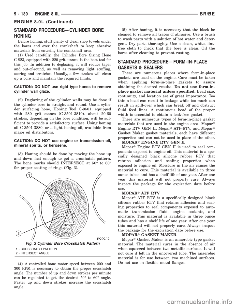
(3) Honing should be done by moving the hone up
and down fast enough to get a crosshatch pattern.
The hone marks should INTERSECT at 50É to 60É
for proper seating of rings (Fig. 3).
(4)
A controlled hone motor speed between 200 and
300 RPM is necessary to obtain the proper crosshatch
angle. The number of up and down strokes per minute
can be regulated to get the desired 50É to 60É angle.
Faster up and down strokes increase the crosshatch
angle.
(5) After honing, it is necessary that the block be
cleaned to remove all traces of abrasive. Use a brush
to wash parts with a solution of hot water and deter-
gent. Dry parts thoroughly. Use a clean, white, lint-
free cloth to check that the bore is clean. Oil the
bores after cleaning to prevent rusting.
STANDARD PROCEDUREÐFORM-IN-PLACE
GASKETS & SEALERS
There are numerous places where form-in-place
gaskets are used on the engine. Care must be taken
when applying form-in-place gaskets to assure
obtaining the desired results.Do not use form-in-
place gasket material unless specified.Bead size,
continuity, and location are of great importance. Too
thin a bead can result in leakage while too much can
result in spill-over which can break off and obstruct
fluid feed lines. A continuous bead of the proper
width is essential to obtain a leak-free gasket.
There are numerous types of form-in-place gasket
materials that are used in the engine area. Mopart
Engine RTV GEN II, MopartATF-RTV, and Mopart
Gasket Maker gasket materials, each have different
properties and can not be used in place of the other.
MOPARtENGINE RTV GEN II
MopartEngine RTV GEN II is used to seal com-
ponents exposed to engine oil. This material is a spe-
cially designed black silicone rubber RTV that
retains adhesion and sealing properties when
exposed to engine oil. Moisture in the air causes the
material to cure. This material is available in three
ounce tubes and has a shelf life of one year. After one
year this material will not properly cure. Always
inspect the package for the expiration date before
use.
MOPARtATF RTV
MopartATF RTV is a specifically designed black
silicone rubber RTV that retains adhesion and seal-
ing properties to seal components exposed to auto-
matic transmission fluid, engine coolants, and
moisture. This material is available in three ounce
tubes and has a shelf life of one year. After one year
this material will not properly cure. Always inspect
the package for the expiration date before use.
MOPARtGASKET MAKER
MopartGasket Maker is an anaerobic type gasket
material. The material cures in the absence of air
when squeezed between two metallic surfaces. It will
not cure if left in the uncovered tube. The anaerobic
material is for use between two machined surfaces.
Do not use on flexible metal flanges.
Fig. 3 Cylinder Bore Crosshatch Pattern
1 - CROSSHATCH PATTERN
2 - INTERSECT ANGLE
9 - 180 ENGINE 8.0LBR/BE
ENGINE 8.0L (Continued)
Page 1328 of 2889
MOPARtGASKET SEALANT
MopartGasket Sealant is a slow drying, perma-
nently soft sealer. This material is recommended for
sealing threaded fittings and gaskets against leakage
of oil and coolant. Can be used on threaded and
machined parts under all temperatures. This mate-
rial is used on engines with multi-layer steel (MLS)
cylinder head gaskets. This material also will pre-
vent corrosion. MopartGasket Sealant is available in
a 13 oz. aerosol can or 4oz./16 oz. can w/applicator.
FORM-IN-PLACE GASKET AND SEALER
APPLICATION
Assembling parts using a form-in-place gasket
requires care but it's easier then using precut gas-
kets.
MopartGasket Maker material should be applied
sparingly 1 mm (0.040 in.) diameter or less of sealant
to one gasket surface. Be certain the material sur-
rounds each mounting hole. Excess material can eas-
ily be wiped off. Components should be torqued in
place within 15 minutes. The use of a locating dowel
is recommended during assembly to prevent smear-
ing material off the location.
MopartEngine RTV GEN II or ATF RTV gasket
material should be applied in a continuous bead
approximately 3 mm (0.120 in.) in diameter. All
mounting holes must be circled. For corner sealing, a
3.17 or 6.35 mm (1/8 or 1/4 in.) drop is placed in the
center of the gasket contact area. Uncured sealant
may be removed with a shop towel. Components
should be torqued in place while the sealant is still
wet to the touch (within 10 minutes). The usage of a
locating dowel is recommended during assembly to
prevent smearing material off the location.
MopartGasket Sealant in an aerosol can should be
applied using a thin, even coat sprayed completely
over both surfaces to be joined, and both sides of a
gasket. Then proceed with assembly. Material in a
can w/applicator can be brushed on evenly over the
sealing surfaces. Material in an aerosol can should be
used on engines with multi-layer steel gaskets.
STANDARD PROCEDUREÐREPAIR DAMAGED
OR WORN THREADS
CAUTION: Be sure that the tapped holes maintain
the original center line.
Damaged or worn threads can be repaired. Essen-
tially, this repair consists of:
²Drilling out worn or damaged threads.
²Tapping the hole with a special Heli-Coil Tap, or
equivalent.
²Installing an insert into the tapped hole to bring
the hole back to its original thread size.
STANDARD PROCEDUREÐHYDROSTATIC
LOCK
CAUTION: DO NOT use the starter motor to rotate
the crankshaft. Severe damage could occur.
When an engine is suspected of hydrostatic lock
(regardless of what caused the problem), follow the
steps below.
(1) Perform the Fuel Pressure Release Procedure
(Refer to 14 - FUEL SYSTEM/FUEL DELIVERY -
STANDARD PROCEDURE).
(2) Disconnect the negative cable(s) from the bat-
tery.
(3) Inspect air cleaner, induction system, and
intake manifold to ensure system is dry and clear of
foreign material.
(4) Place a shop towel around the spark plugs to
catch any fluid that may possibly be under pressure
in the cylinder head. Remove the spark plugs.
(5) With all spark plugs removed, rotate the crank-
shaft using a breaker bar and socket.
(6) Identify the fluid in the cylinders (coolant, fuel,
oil, etc.).
(7) Be sure all fluid has been removed from the
cylinders.
(8) Repair engine or components as necessary to
prevent this problem from occurring again.
(9) Squirt a small amount of engine oil into the
cylinders to lubricate the walls. This will prevent
damage on restart.
(10) Install new spark plugs. Tighten the spark
plugs to 41 N´m (30 ft. lbs.) torque.
(11) Drain engine oil. Remove and discard the oil
filter.
(12) Install the drain plug. Tighten the plug to 34
N´m (25 ft. lbs.) torque.
(13) Install a new oil filter.
(14) Fill engine crankcase with the specified
amount and grade of oil. (Refer to LUBRICATION &
MAINTENANCE - SPECIFICATIONS).
(15) Connect the negative cable(s) to the battery.
(16) Start the engine and check for any leaks.
REMOVAL
(1) Remove the battery.
(2) Drain cooling system (Refer to 7 - COOLING -
STANDARD PROCEDURE).
(3) Discharge the air conditioning system, if
equipped (Refer to 24 - HEATING & AIR CONDI-
TIONING/PLUMBING - STANDARD PROCEDURE).
(4) Remove the upper crossmember.
(5) Remove the transmission oil cooler (Refer to 7 -
COOLING/TRANSMISSION/TRANS COOLER -
REMOVAL).
BR/BEENGINE 8.0L 9 - 181
ENGINE 8.0L (Continued)
Page 1329 of 2889
(6) Remove the serpentine belt (Refer to 7 - COOL-
ING/ACCESSORY DRIVE/DRIVE BELTS - REMOV-
AL).
(7) Remove the A/C compressor with the lines
attached (Refer to 24 - HEATING & AIR CONDI-
TIONING/PLUMBING/A/C COMPRESSOR -
REMOVAL). Set aside.
(8) If equipped, remove the condenser (Refer to 24
- HEATING & AIR CONDITIONING/PLUMBING/
A/C CONDENSER - REMOVAL).
(9) Remove the washer fluid reservoir bottle (Refer
to 8 - ELECTRICAL/WIPERS/WASHERS -
REMOVAL AND INSTALLATION).
(10) Disconnect the top radiator hose.
(11) Remove the fan (Refer to 7 - COOLING/EN-
GINE/RADIATOR FAN - REMOVAL).
(12) Remove the fan shroud.
(13) Disconnect the lower radiator hose.
(14) Disconnect the transmission cooler lines.
(15) Remove radiator (Refer to 7 - COOLING/EN-
GINE/RADIATOR - REMOVAL).
(16) Remove the generator with the wire connec-
tions (Refer to 8 - ELECTRICAL/CHARGING/GEN-
ERATOR - REMOVAL).
(17) Remove the air cleaner.
(18) Disconnect the throttle linkage.
(19) Remove throttle body (Refer to 14 - FUEL
SYSTEM/FUEL INJECTION/THROTTLE BODY -
REMOVAL).
(20) Remove the upper intake manifold (Refer to 9
- ENGINE/MANIFOLDS/INTAKE MANIFOLD -
REMOVAL).
(21) Remove the coil assemblies with the ignition
cables.
(22) Disconnect the heater hoses.
(23) Disconnect the power steering hoses, if
equipped.
(24) Perform the Fuel System Pressure release
procedure (Refer to 14 - FUEL SYSTEM/FUEL
DELIVERY - STANDARD PROCEDURE). Disconnect
the fuel line (Refer to 14 - FUEL SYSTEM/FUEL
DELIVERY/QUICK CONNECT FITTING - STAN-
DARD PROCEDURE).
(25) On Manual Transmission vehicles, remove the
shift lever.
(26) Raise and support the vehicle on a hoist.
(27) Remove the drain plug and drain the engine
oil.
(28) Loosen front engine mount thru-bolt nuts.
(29) Remove the transmission cooler line brackets
from oil pan.
(30) Disconnect exhaust pipe at manifold.
(31) Disconnect the starter wires. Remove starter
motor (Refer to 8 - ELECTRICAL/STARTING/
STARTER MOTOR - REMOVAL).
(32) Remove transmission.(33) Lower vehicle.
CAUTION: DO NOT lift the engine by the intake
manifold.
(34) Install an engine lifting fixture.
(35) Remove engine from vehicle and install
engine assembly on a repair stand.
INSTALLATION
(1) Remove engine from the repair stand and posi-
tion in the engine compartment. Position the thru-
bolt into the support cushion brackets.
(2) Install an engine support fixture.
(3) Raise and support the vehicle on a hoist.
(4) Install Transmission.
(5) Install the starter and connect the starter
wires (Refer to 8 - ELECTRICAL/STARTING/
STARTER MOTOR - INSTALLATION).
(6) Install exhaust pipe to manifold.
(7) Install the transmission cooler line brackets
from oil pan.
(8) Tighten the Front mount thru-bolts and nuts to
102N´m (75 ft. lbs.).
(9) Install the drain plug and tighten to 34 N´m
(25 ft. lbs.) torque.
(10) Prime oil pump by squirting oil in the oil fil-
ter mounting hole and filling the J-trap of the front
timing cover. When oil is running out, install oil filter
that has been filled with oil.
(11) Lower the vehicle.
(12) Remove engine lifting fixture.
(13) On Manual Transmission vehicles, install the
shift lever.
(14) Connect the fuel lines (Refer to 14 - FUEL
SYSTEM/FUEL DELIVERY/QUICK CONNECT FIT-
TING - STANDARD PROCEDURE).
(15) Connect the heater hoses.
(16) Install the upper intake manifold (Refer to 9 -
ENGINE/MANIFOLDS/INTAKE MANIFOLD -
INSTALLATION).
(17) Install the coil assemblies with the ignition
cables.
(18) Using a new gasket, install throttle body
(Refer to 14 - FUEL SYSTEM/FUEL INJECTION/
THROTTLE BODY - INSTALLATION).
(19) Connect the throttle linkage.
(20) Install the air cleaner box.
(21) Install the generator and wire connections
(Refer to 8 - ELECTRICAL/CHARGING/GENERA-
TOR - INSTALLATION).
(22) Install the upper crossmember.
(23) Install radiator (Refer to 7 - COOLING/EN-
GINE/RADIATOR - INSTALLATION).
(24) Connect the lower radiator hose.
9 - 182 ENGINE 8.0LBR/BE
ENGINE 8.0L (Continued)
Page 1330 of 2889
(25) Install the transmission oil cooler (Refer to 7 -
COOLING/TRANSMISSION/TRANS COOLER -
INSTALLATION).
(26) Connect the transmission cooler lines.
(27) Connect the power steering hoses, if equipped.
(28) Install the fan shroud.
(29) Install the fan (Refer to 7 - COOLING/EN-
GINE/RADIATOR FAN - INSTALLATION).
(30) Connect the top radiator hose.
(31) Install the washer fluid reservoir bottle (Refer
to 8 - ELECTRICAL/WIPERS/WASHERS - INSTAL-
LATION).
(32) If equipped, install the condenser (Refer to 24
- HEATING & AIR CONDITIONING/PLUMBING/
A/C CONDENSER - INSTALLATION).
(33) Install the A/C compressor with the lines
attached (Refer to 24 - HEATING & AIR CONDI-TIONING/PLUMBING/A/C COMPRESSOR -
INSTALLATION).
(34) Install the serpentine belt (Refer to 7 - COOL-
ING/ACCESSORY DRIVE/DRIVE BELTS - INSTAL-
LATION).
(35) Evacuate (Refer to 24 - HEATING & AIR
CONDITIONING/PLUMBING - STANDARD PRO-
CEDURE) and charge the air conditioning system, if
equipped (Refer to 24 - HEATING & AIR CONDI-
TIONING/PLUMBING - STANDARD PROCEDURE).
(36) Add coolant to the cooling system (Refer to 7 -
COOLING - STANDARD PROCEDURE).
(37) Install the battery.
(38) Warm engine and adjust as required.
(39) Road test vehicle.
BR/BEENGINE 8.0L 9 - 183
ENGINE 8.0L (Continued)
Page 1334 of 2889
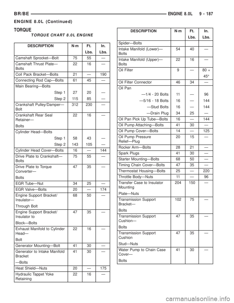
TORQUE
TORQUE CHART 8.0L ENGINE
DESCRIPTION N´m Ft. In.
Lbs. Lbs.
Camshaft SprocketÐBolt 75 55 Ð
Camshaft Thrust PlateÐ
Bolts22 16 Ð
Coil Pack BracketÐBolts 21 Ð 190
Connecting Rod CapÐBolts 61 45 Ð
Main BearingÐBolts
Step 1 27 20 Ð
Step 2 115 85 Ð
Crankshaft Pulley/DamperÐ
Bolt312 230 Ð
Crankshaft Rear Seal
RetainerÐ22 16 Ð
Bolts
Cylinder HeadÐBolts
Step 1 58 43 Ð
Step 2 143 105 Ð
Cylinder Head CoverÐBolts 16 Ð 144
Drive Plate to CrankshaftÐ
Bolts75 55 Ð
Drive Plate to Torque
ConverterÐ47 35 Ð
Bolts
EGR TubeÐNut 34 25 Ð
EGR ValveÐBolts 20 Ð 174
Engine Support Bracket/
InsulatorÐ68 50 Ð
Through Bolt
Engine Support Bracket/
Insulator to47 35 Ð
BlockÐBolts
Exhaust Manifold to Cylinder
HeadÐ22 16 Ð
Bolt
Generator MountingÐBolt 41 30 Ð
Generator to Intake Manifold
Bracket41 30 Ð
ÐBolts
Heat ShieldÐNuts 20 Ð 175
Hydraulic Tappet Yoke
Retaining22 16 Ð
DESCRIPTION N´m Ft. In.
Lbs. Lbs.
SpiderÐBolts
Intake Manifold (Lower)Ð
Bolts54 40 Ð
Intake Manifold (Upper)Ð
Bolts22 16 Ð
Oil Filter 9 Ð 80 +
45É
Oil Filter Connector 46 34 Ð
Oil Pan
Ð1/4 - 20 Bolts 11 Ð 96
Ð5/16 - 18 Bolts 16 Ð 144
ÐStud Bolts 16 Ð 144
ÐDrain Plug 34 25 Ð
Oil Pan Pick Up TubeÐBolts 16 Ð 144
Oil Pump AttachingÐBolts 41 30 Ð
Oil Pump CoverÐBolts 14 Ð 125
Oil Pump Pressure
ReliefÐPlug20 15 Ð
Rocker ArmÐBolts 28 21 Ð
Spark Plugs 41 30 Ð
Starter MountingÐBolts 68 50 Ð
Timing Chain CoverÐBolts 47 35 Ð
Thermostat HousingÐBolts 25 Ð 220
Throttle BodyÐNuts 11 Ð 96
Transfer Case to Insulator
Mounting204 150 Ð
PlateÐNuts
Transmission Support
BracketÐ102 75 Ð
Bolts
Transmission Support
CushionÐ47 35 Ð
Bolts
Transmission Support
Cushion47 35 Ð
StudÐNuts
Water Pump to Chain Case
CoverÐ41 30 Ð
Bolts
BR/BEENGINE 8.0L 9 - 187
ENGINE 8.0L (Continued)
Page 1339 of 2889
COOLING SYSTEM TESTER METHOD
WARNING: WITH COOLING SYSTEM TESTER IN
PLACE, PRESSURE WILL BUILD UP FAST. EXCES-
SIVE PRESSURE BUILT UP, BY CONTINUOUS
ENGINE OPERATION, MUST BE RELEASED TO A
SAFE PRESSURE POINT. NEVER PERMIT PRES-
SURE TO EXCEED 138 kPa (20 psi).
Install Cooling System Tester 7700 or equivalent to
pressure cap neck. Start the engine and observe the
tester's pressure gauge. If gauge pulsates with every
power stroke of a cylinder a combustion pressure
leak is evident.
CHEMICAL TEST METHOD
Combustion leaks into the cooling system can also
be checked by using Bloc-Chek Kit C-3685-A or
equivalent. Perform test following the procedures
supplied with the tool kit.
REMOVAL
(1) Disconnect the negative cable from the battery.
(2) Drain cooling system (Refer to 7 - COOLING -
STANDARD PROCEDURE).
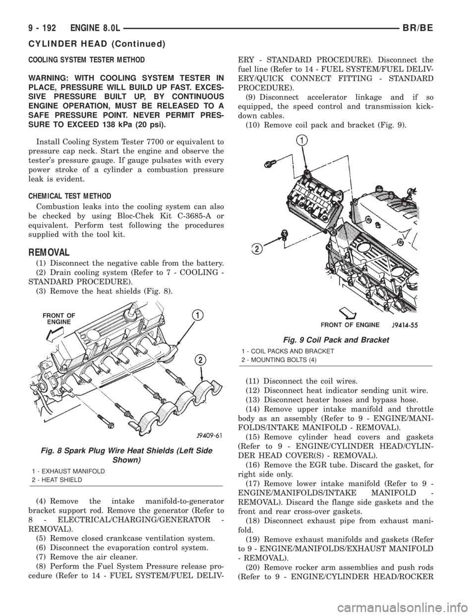
(3) Remove the heat shields (Fig. 8).
(4) Remove the intake manifold-to-generator
bracket support rod. Remove the generator (Refer to
8 - ELECTRICAL/CHARGING/GENERATOR -
REMOVAL).
(5) Remove closed crankcase ventilation system.
(6) Disconnect the evaporation control system.
(7) Remove the air cleaner.
(8) Perform the Fuel System Pressure release pro-
cedure (Refer to 14 - FUEL SYSTEM/FUEL DELIV-ERY - STANDARD PROCEDURE). Disconnect the
fuel line (Refer to 14 - FUEL SYSTEM/FUEL DELIV-
ERY/QUICK CONNECT FITTING - STANDARD
PROCEDURE).
(9) Disconnect accelerator linkage and if so
equipped, the speed control and transmission kick-
down cables.
(10) Remove coil pack and bracket (Fig. 9).
(11) Disconnect the coil wires.
(12) Disconnect heat indicator sending unit wire.
(13) Disconnect heater hoses and bypass hose.
(14) Remove upper intake manifold and throttle
body as an assembly (Refer to 9 - ENGINE/MANI-
FOLDS/INTAKE MANIFOLD - REMOVAL).
(15) Remove cylinder head covers and gaskets
(Refer to 9 - ENGINE/CYLINDER HEAD/CYLIN-
DER HEAD COVER(S) - REMOVAL).
(16) Remove the EGR tube. Discard the gasket, for
right side only.
(17) Remove lower intake manifold (Refer to 9 -
ENGINE/MANIFOLDS/INTAKE MANIFOLD -
REMOVAL). Discard the flange side gaskets and the
front and rear cross-over gaskets.
(18) Disconnect exhaust pipe from exhaust mani-
fold.
(19) Remove exhaust manifolds and gaskets (Refer
to 9 - ENGINE/MANIFOLDS/EXHAUST MANIFOLD
- REMOVAL).
(20) Remove rocker arm assemblies and push rods
(Refer to 9 - ENGINE/CYLINDER HEAD/ROCKER
Fig. 8 Spark Plug Wire Heat Shields (Left Side
Shown)
1 - EXHAUST MANIFOLD
2 - HEAT SHIELD
Fig. 9 Coil Pack and Bracket
1 - COIL PACKS AND BRACKET
2 - MOUNTING BOLTS (4)
9 - 192 ENGINE 8.0LBR/BE
CYLINDER HEAD (Continued)
Page 1340 of 2889
ARM / ADJUSTER ASSY - REMOVAL). Identify to
ensure installation in original locations.
(21) Remove the head bolts from each cylinder
head and remove cylinder heads. Discard the cylin-
der head gasket.
(22) Remove spark plugs.
CLEANING
Clean all surfaces of cylinder block and cylinder
heads. Be sure material does not fall into the lifters
and surrounding valley.
Clean cylinder block front and rear gasket surfaces
using a suitable solvent.
Clean the exhaust manifold to cylinder head mat-
ing areas.
INSPECTION
Inspect all surfaces with a straightedge if there is
any reason to suspect leakage. The out-of-flatness
specifications are 0.0007 mm/mm (0.0004 inch/inch),
0.127 mm/152 mm (0.005 inch/6 inches) any direction
or 0.254 mm (0.010 inch) overall across head. If
exceeded, either replace head or lightly machine the
head surface.
The cylinder head surface finish should be
1.78-4.57 microns (15-80 microinches).
Inspect push rods. Replace worn or bent rods.
Inspect rocker arms. Replace if worn or scored.
INSTALLATION
(1) Position the new cylinder head gaskets onto
the cylinder block.
(2) Position the cylinder heads onto head gaskets
and cylinder block.
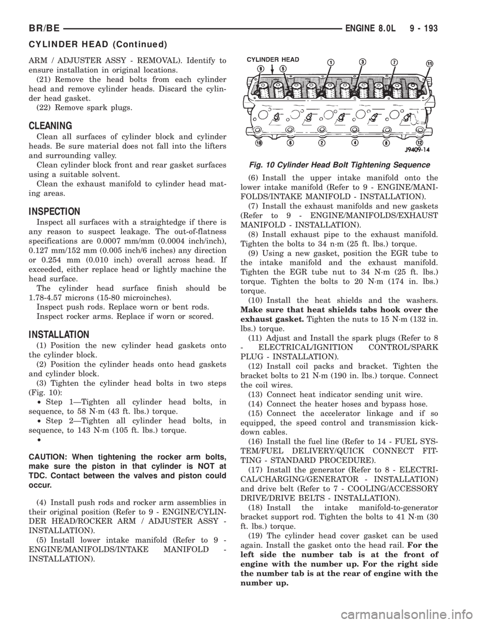
(3) Tighten the cylinder head bolts in two steps
(Fig. 10):
²Step 1ÐTighten all cylinder head bolts, in
sequence, to 58 N´m (43 ft. lbs.) torque.
²Step 2ÐTighten all cylinder head bolts, in
sequence, to 143 N´m (105 ft. lbs.) torque.
²
CAUTION: When tightening the rocker arm bolts,
make sure the piston in that cylinder is NOT at
TDC. Contact between the valves and piston could
occur.
(4) Install push rods and rocker arm assemblies in
their original position (Refer to 9 - ENGINE/CYLIN-
DER HEAD/ROCKER ARM / ADJUSTER ASSY -
INSTALLATION).
(5) Install lower intake manifold (Refer to 9 -
ENGINE/MANIFOLDS/INTAKE MANIFOLD -
INSTALLATION).(6) Install the upper intake manifold onto the
lower intake manifold (Refer to 9 - ENGINE/MANI-
FOLDS/INTAKE MANIFOLD - INSTALLATION).
(7) Install the exhaust manifolds and new gaskets
(Refer to 9 - ENGINE/MANIFOLDS/EXHAUST
MANIFOLD - INSTALLATION).
(8) Install exhaust pipe to the exhaust manifold.
Tighten the bolts to 34 n´m (25 ft. lbs.) torque.
(9) Using a new gasket, position the EGR tube to
the intake manifold and the exhaust manifold.
Tighten the EGR tube nut to 34 N´m (25 ft. lbs.)
torque. Tighten the bolts to 20 N´m (174 in. lbs.)
torque.
(10) Install the heat shields and the washers.
Make sure that heat shields tabs hook over the
exhaust gasket.Tighten the nuts to 15 N´m (132 in.
lbs.) torque.
(11) Adjust and Install the spark plugs (Refer to 8
- ELECTRICAL/IGNITION CONTROL/SPARK
PLUG - INSTALLATION).
(12) Install coil packs and bracket. Tighten the
bracket bolts to 21 N´m (190 in. lbs.) torque. Connect
the coil wires.
(13) Connect heat indicator sending unit wire.
(14) Connect the heater hoses and bypass hose.
(15) Connect the accelerator linkage and if so
equipped, the speed control and transmission kick-
down cables.
(16) Install the fuel line (Refer to 14 - FUEL SYS-
TEM/FUEL DELIVERY/QUICK CONNECT FIT-
TING - STANDARD PROCEDURE).
(17) Install the generator (Refer to 8 - ELECTRI-
CAL/CHARGING/GENERATOR - INSTALLATION)
and drive belt (Refer to 7 - COOLING/ACCESSORY
DRIVE/DRIVE BELTS - INSTALLATION).
(18) Install the intake manifold-to-generator
bracket support rod. Tighten the bolts to 41 N´m (30
ft. lbs.) torque.
(19) The cylinder head cover gasket can be used
again. Install the gasket onto the head rail.For the
left side the number tab is at the front of
engine with the number up. For the right side
the number tab is at the rear of engine with the
number up.
Fig. 10 Cylinder Head Bolt Tightening Sequence
BR/BEENGINE 8.0L 9 - 193
CYLINDER HEAD (Continued)
Page 1350 of 2889
is not required when a crankshaft and bearings are
replaced.
(1) Remove the oil pan and oil pickup tube (refer
to Oil Pan in this section for correct procedure).
(2) Remove the timing chain cover and gasket.
Remove and discard the front crankshaft oil seal and
cover gasket.
(3) Remove Transmission (refer to Group 21,
Transmission).
(4) Remove the rear seal retainer (refer to Crank-
shaft Rear Seal Retainer in this section for correct
procedure).
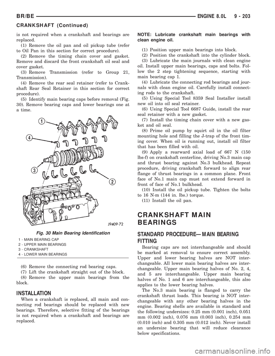
(5) Identify main bearing caps before removal (Fig.
30). Remove bearing caps and lower bearings one at
a time.
(6) Remove the connecting rod bearing caps.
(7) Lift the crankshaft straight out of the block.
(8) Remove the upper main bearings from the
block.
INSTALLATION
When a crankshaft is replaced, all main and con-
necting rod bearings should be replaced with new
bearings. Therefore, selective fitting of the bearings
is not required when a crankshaft and bearings are
replaced.NOTE: Lubricate crankshaft main bearings with
clean engine oil.
(1) Position upper main bearings into block.
(2) Position the crankshaft into the cylinder block.
(3) Lubricate the main journals with clean engine
oil. Install upper main bearings, caps and bolts. Fol-
low the 2 step tightening sequence, starting with
main bearing cap 1.
(4) Lubricate the connecting rod bearings and jour-
nals with clean engine oil. Carefully install connect-
ing rods to the crankshaft.
(5) Using Special Tool 8359 Seal Installer install
new oil into oil seal retainer.
(6) Using Special Tool 6687 Guide, install the rear
seal retainer with a new gasket.
(7) Install the timing chain cover with a new gas-
ket and oil seal.
(8) Prime oil pump by squirt oil in the oil filter
mounting hole and filling the J-trap of the front tim-
ing cover. When oil is running out, install oil filter
that has been filled with oil.
(9) Apply a rearward axial load of 667 N (150
lbs-f) on crankshaft centerline, driving No.3 main cap
and thrust bearing against No.3 bulkhead. Repeat
procedure, driving crankshaft forward to align rear
flange of thrust bearings in a common plane. Front
face of No.1 main cap must not extend forward in
front of face of No.1 bulkhead.
(10) Install the oil pickup tube. Tighten the bolts
to 16 N´m (144 in. lbs.) torque.
(11) Install the oil pan.
CRANKSHAFT MAIN
BEARINGS
STANDARD PROCEDUREÐMAIN BEARING
FITTING
Bearing caps are not interchangeable and should
be marked at removal to ensure correct assembly.
Upper and lower bearing halves are NOT inter-
changeable. All lower main bearing halves are inter-
changeable. Upper main bearing halves of No. 2, 4,
and 5 are interchangeable. Upper main bearing
halves of No. 1 and 6 are interchangeable, this also
applies to the lower bearing halves.
The No.3 main bearing is flanged to carry the
crankshaft thrust loads. This bearing is NOT inter-
changeable with any other bearing halves in the
engine. Bearing shells are available in standard and
the following undersizes: 0.25 mm (0.001 inch), 0.051
mm (0.002 inch), 0.076 mm (0.003 inch), 0.254 mm
(0.010 inch) and 0.305 mm (0.012 inch). Never install
an undersize bearing that will reduce clearance
below specifications.
Fig. 30 Main Bearing Identification
1 - MAIN BEARING CAP
2 - UPPER MAIN BEARINGS
3 - CRANKSHAFT
4 - LOWER MAIN BEARINGS
BR/BEENGINE 8.0L 9 - 203
CRANKSHAFT (Continued)