2001 DODGE RAM transmission oil
[x] Cancel search: transmission oilPage 1465 of 2889
proper alignment with other parts in the system and
provide acceptable exhaust noise levels.
INSTALLATION
(1) Install the exhaust pipe into the transmission
support and onto the turbocharger flange (Fig. 11).
(2) Install the exhaust pipe-to-turbocharger elbow
bolts and tighten to 31 N´m (23 ft. lbs.) torque.
(3) Install the extension pipe and clamp to the
exhaust pipe using a new clamp and tighten the
clamp nuts to 48 N´m (35 ft. lbs.) torque.
(4) Lower the vehicle.
(5) Connect the battery negative cables.
(6) Start the engine and inspect for exhaust leaks
and exhaust system contact with the body panels. A
minimum of 25.4 mm (1.0 in.) is required. Adjust the
alignment, if needed.
HEAT SHIELDS
DESCRIPTION
There are two types of heat shields used. One is
stamped steel the other is molded foil sheets. The
shields attach to the vehicle around the exhaust sys-
tem to prevent heat from the exhaust system fromentering the passenger area and other areas where
the heat can cause damage to other components.
REMOVAL
(1) Raise and support the vehicle.
(2) Remove the nuts or bolts holding the exhaust
heat shield to the floor pan, crossmember or bracket.
(3) Slide the shield out around the exhaust system.
INSTALLATION
(1)Position the exhaust heat shield to the floor pan,
crossmember or bracket and install the nuts or bolts.
(2)Tighten the nuts and bolts 11 N´m (100 in. lbs.).
(3) Lower the vehicle.
MUFFLER - 3.9L/5.2L/5.9L/8.0L
REMOVAL
(1) Raise and support the vehicle.
(2) Saturate the clamp nuts with heat valve lubri-
cant. Allow 5 minutes for penetration.
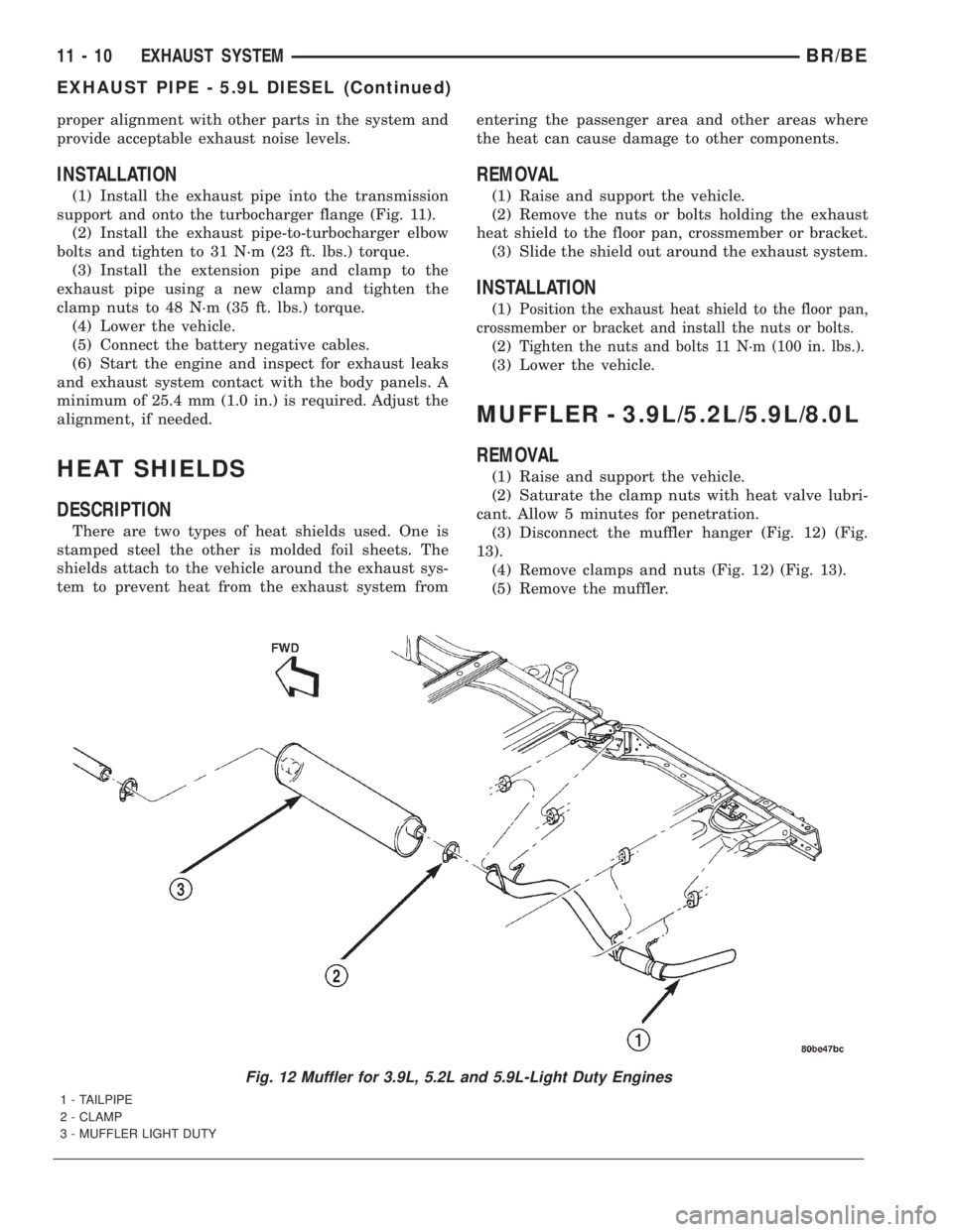
(3) Disconnect the muffler hanger (Fig. 12) (Fig.
13).
(4) Remove clamps and nuts (Fig. 12) (Fig. 13).
(5) Remove the muffler.
Fig. 12 Muffler for 3.9L, 5.2L and 5.9L-Light Duty Engines
1 - TAILPIPE
2 - CLAMP
3 - MUFFLER LIGHT DUTY
11 - 10 EXHAUST SYSTEMBR/BE
EXHAUST PIPE - 5.9L DIESEL (Continued)
Page 1473 of 2889
(3) Remove the front support bracket.
(4) Discharge the A/C system (Refer to 24 - HEAT-
ING & AIR CONDITIONING/PLUMBING - STAN-
DARD PROCEDURE) and remove the A/C condenser
(Refer to 24 - HEATING & AIR CONDITIONING/
PLUMBING/A/C CONDENSER - REMOVAL) (Fig.
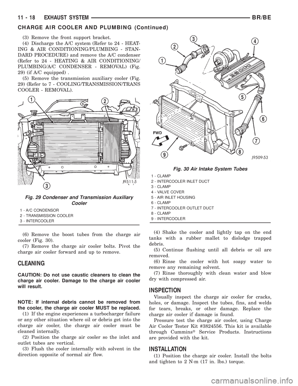
29) (if A/C equipped) .
(5) Remove the transmission auxiliary cooler (Fig.
29) (Refer to 7 - COOLING/TRANSMISSION/TRANS
COOLER - REMOVAL).
(6) Remove the boost tubes from the charge air
cooler (Fig. 30).
(7) Remove the charge air cooler bolts. Pivot the
charge air cooler forward and up to remove.
CLEANING
CAUTION: Do not use caustic cleaners to clean the
charge air cooler. Damage to the charge air cooler
will result.
NOTE: If internal debris cannot be removed from
the cooler, the charge air cooler MUST be replaced.
(1) If the engine experiences a turbocharger failure
or any other situation where oil or debris get into the
charge air cooler, the charge air cooler must be
cleaned internally.
(2) Position the charge air cooler so the inlet and
outlet tubes are vertical.
(3) Flush the cooler internally with solvent in the
direction opposite of normal air flow.(4) Shake the cooler and lightly tap on the end
tanks with a rubber mallet to dislodge trapped
debris.
(5) Continue flushing until all debris or oil are
removed.
(6) Rinse the cooler with hot soapy water to
remove any remaining solvent.
(7) Rinse thoroughly with clean water and blow
dry with compressed air.
INSPECTION
Visually inspect the charge air cooler for cracks,
holes, or damage. Inspect the tubes, fins, and welds
for tears, breaks, or other damage. Replace the
charge air cooler if damage is found.
Pressure test the charge air cooler, using Charge
Air Cooler Tester Kit #3824556. This kit is available
through CumminstService Products. Instructions
are provided with the kit.
INSTALLATION
(1) Position the charge air cooler. Install the bolts
and tighten to 2 N´m (17 in. lbs.) torque.
Fig. 29 Condenser and Transmission Auxiliary
Cooler
1 - A/C CONDENSOR
2 - TRANSMISSION COOLER
3 - INTERCOOLER
Fig. 30 Air Intake System Tubes
1 - CLAMP
2 - INTERCOOLER INLET DUCT
3 - CLAMP
4 - VALVE COVER
5 - AIR INLET HOUSING
6 - CLAMP
7 - INTERCOOLER OUTLET DUCT
8 - CLAMP
9 - INTERCOOLER
11 - 18 EXHAUST SYSTEMBR/BE
CHARGE AIR COOLER AND PLUMBING (Continued)
Page 1519 of 2889
VISUAL INSPECTIONÐ8.0L ENGINE
A visual inspection for loose, disconnected or incor-
rectly routed wires and hoses should be made. This
should be done before attempting to diagnose or ser-
vice the fuel injection system. A visual check will
help spot these faults and save unnecessary test and
diagnostic time. A thorough visual inspection will
include the following checks:
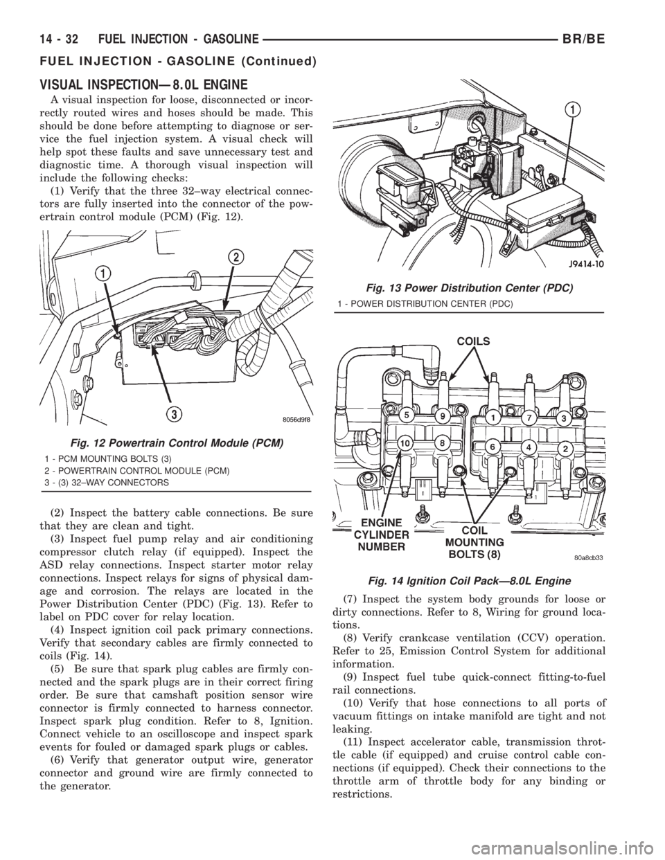
(1) Verify that the three 32±way electrical connec-
tors are fully inserted into the connector of the pow-
ertrain control module (PCM) (Fig. 12).
(2) Inspect the battery cable connections. Be sure
that they are clean and tight.
(3) Inspect fuel pump relay and air conditioning
compressor clutch relay (if equipped). Inspect the
ASD relay connections. Inspect starter motor relay
connections. Inspect relays for signs of physical dam-
age and corrosion. The relays are located in the
Power Distribution Center (PDC) (Fig. 13). Refer to
label on PDC cover for relay location.
(4) Inspect ignition coil pack primary connections.
Verify that secondary cables are firmly connected to
coils (Fig. 14).
(5) Be sure that spark plug cables are firmly con-
nected and the spark plugs are in their correct firing
order. Be sure that camshaft position sensor wire
connector is firmly connected to harness connector.
Inspect spark plug condition. Refer to 8, Ignition.
Connect vehicle to an oscilloscope and inspect spark
events for fouled or damaged spark plugs or cables.
(6) Verify that generator output wire, generator
connector and ground wire are firmly connected to
the generator.(7) Inspect the system body grounds for loose or
dirty connections. Refer to 8, Wiring for ground loca-
tions.
(8) Verify crankcase ventilation (CCV) operation.
Refer to 25, Emission Control System for additional
information.
(9) Inspect fuel tube quick-connect fitting-to-fuel
rail connections.
(10) Verify that hose connections to all ports of
vacuum fittings on intake manifold are tight and not
leaking.
(11) Inspect accelerator cable, transmission throt-
tle cable (if equipped) and cruise control cable con-
nections (if equipped). Check their connections to the
throttle arm of throttle body for any binding or
restrictions.
Fig. 12 Powertrain Control Module (PCM)
1 - PCM MOUNTING BOLTS (3)
2 - POWERTRAIN CONTROL MODULE (PCM)
3 - (3) 32±WAY CONNECTORS
Fig. 13 Power Distribution Center (PDC)
1 - POWER DISTRIBUTION CENTER (PDC)
Fig. 14 Ignition Coil PackÐ8.0L Engine
14 - 32 FUEL INJECTION - GASOLINEBR/BE
FUEL INJECTION - GASOLINE (Continued)
Page 1624 of 2889
PUMP
TABLE OF CONTENTS
page page
PUMP
DESCRIPTION...........................31
OPERATION.............................31
DIAGNOSIS AND TESTING.................31
PUMP LEAKAGE.......................31
STANDARD PROCEDURE..................31
POWER STEERING PUMP - INITIAL
OPERATION...........................31
FLUSHING POWER STEERING SYSTEM.....32
REMOVAL..............................33
INSTALLATION...........................35SPECIAL TOOLS.........................36
PULLEY
REMOVAL..............................36
INSTALLATION...........................36
HOSES - PRESSURE
DESCRIPTION...........................37
OPERATION.............................37
HOSES - RETURN
DESCRIPTION...........................37
OPERATION.............................37
PUMP
DESCRIPTION
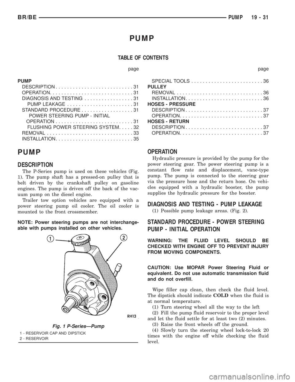
The P-Series pump is used on these vehicles (Fig.
1). The pump shaft has a pressed-on pulley that is
belt driven by the crankshaft pulley on gasoline
engines. The pump is driven off the back of the vac-
uum pump on the diesel engine.
Trailer tow option vehicles are equipped with a
power steering pump oil cooler. The oil cooler is
mounted to the front crossmember.
NOTE: Power steering pumps are not interchange-
able with pumps installed on other vehicles.
OPERATION
Hydraulic pressure is provided by the pump for the
power steering gear. The power steering pump is a
constant flow rate and displacement, vane-type
pump. The pump is connected to the steering gear
via the pressure hose and the return hose. On vehi-
cles equipped with a hydraulic booster, the pump
supplies the hydraulic pressure for the booster.
DIAGNOSIS AND TESTING - PUMP LEAKAGE
(1) Possible pump leakage areas. (Fig. 2).
STANDARD PROCEDURE - POWER STEERING
PUMP - INITIAL OPERATION
WARNING: THE FLUID LEVEL SHOULD BE
CHECKED WITH ENGINE OFF TO PREVENT INJURY
FROM MOVING COMPONENTS.
CAUTION: Use MOPAR Power Steering Fluid or
equivalent. Do not use automatic transmission fluid
and do not overfill.
Wipe filler cap clean, then check the fluid level.
The dipstick should indicateCOLDwhen the fluid is
at normal temperature.
(1) Turn steering wheel all the way to the left
(2) Fill the pump fluid reservoir to the proper level
and let the fluid settle for at least two (2) minutes.
(3) Raise the front wheels off the ground.
(4) Slowly turn the steering wheel lock-to-lock 20
times with the engine off while checking the fluid
level.
Fig. 1 P-SeriesÐPump
1 - RESERVOIR CAP AND DIPSTICK
2 - RESERVOIR
BR/BEPUMP 19 - 31
Page 1638 of 2889
The driver selects a particular gear by moving the
shift lever to the desired gear position. This move-
ment moves the internal transmission shift compo-
nents to begin the shift sequence. As the shift lever
moves the selected shift rail, the shift fork attached
to that rail begins to move. The fork is positioned in
a groove in the outer circumference of the synchro-
nizer sleeve. As the shift fork moves the synchronizer
sleeve, the synchronizer begins to speed-up or slow
down the selected gear (depending on whether we are
up-shifting or down-shifting). The synchronizer does
this by having the synchronizer hub splined to the
mainshaft, or the countershaft in some cases, and
moving the blocker ring into contact with the gear's
friction cone. As the blocker ring and friction cone
come together, the gear speed is brought up or down
to the speed of the synchronizer. As the two speeds
match, the splines on the inside of the synchronizer
sleeve become aligned with the teeth on the blocker
ring and the friction cone and eventually will slide
over the teeth, locking the gear to the mainshaft, or
countershaft, through the synchronizer.
DIAGNOSIS AND TESTING - MANUAL
TRANSMISSION
LOW LUBRICANT LEVEL
A low transmission lubricant level is generally the
result of a leak, inadequate lubricant fill or an incor-
rect lubricant level check.
Leaks can occur at the mating surfaces of the gear
case, adaptor or extension housing, or from the front/
rear seals. A suspected leak could also be the result
of an overfill condition.
Leaks at the rear of the extension or adapter hous-
ing will be from the housing oil seals. Leaks at com-
ponent mating surfaces will probably be the result of
inadequate sealer, gaps in the sealer, incorrect bolt
tightening or use of a non-recommended sealer.
A leak at the front of the transmission will be from
either the front bearing retainer or retainer seal.
Lubricant may be seen dripping from the clutch
housing after extended operation. If the leak is
severe, it may also contaminate the clutch disc caus-
ing the disc to slip, grab and or chatter.
A correct lubricant level check can only be made
when the vehicle is level. Also allow the lubricant to
settle for a minute or so before checking. These rec-
ommendations will ensure an accurate check and
avoid an underfill or overfill condition. Always check
the lubricant level after any addition of fluid to avoid
an incorrect lubricant level condition.
HARD SHIFTING
Hard shifting is usually caused by a low lubricant
level, improper or contaminated lubricants. The con-sequence of using non-recommended lubricants is
noise, excessive wear, internal bind and hard shift-
ing. Substantial lubricant leaks can result in gear,
shift rail, synchro, and bearing damage. If a leak
goes undetected for an extended period, the first indi-
cations of component damage are usually hard shift-
ing and noise.
Component damage, incorrect clutch adjustment or
damaged clutch pressure plate or disc are additional
probable causes of increased shift effort. Incorrect
adjustment or a worn/damaged pressure plate or disc
can cause incorrect release. If clutch problem is
advanced, gear clash during shifts can result. Worn
or damaged synchro rings can cause gear clash when
shifting into any forward gear. In some new or
rebuilt transmissions, new synchro rings may tend to
stick slightly causing hard or noisy shifts. In most
cases this condition will decline as the rings wear-in.
TRANSMISSION NOISE
Most manual transmissions make some noise dur-
ing normal operation. Rotating gears generate a mild
whine that is audible, but generally only at extreme
speeds.
Severe highly audible transmission noise is gener-
ally the initial indicator of a lubricant problem.
Insufficient, improper or contaminated lubricant will
promote rapid wear of gears, synchros, shift rails,
forks and bearings. The overheating caused by a
lubricant problem, can also lead to gear breakage.
REMOVAL
(1) Disconnect battery negative cable.
(2) Shift transmission into Neutral.
(3) Remove shift boot bezel screws and slide boot
upward on shift lever extension.
(4) Remove shift lever extension from the shift
tower and lever assembly.
(5) Remove bolts attaching shift tower and lever
assembly to rear case. Then remove shift tower and
lever assembly.
(6) Raise vehicle on hoist.
(7) Remove crankshaft position sensor. Retain sen-
sor attaching bolts.
(8) Remove skid plate, if equipped.
(9) Drain transmission lubricant if transmission
will be disassembled for service.
(10) Mark propeller shaft/shafts and yoke/yokes for
installation reference and remove propeller shaft/
shafts.
(11) Disengage harness from clips on transmission
housing.
(12) Support engine with adjustable jack stand
and wood block.
(13) Drain transmission lubricant if transmission
will be disassembled for service.
BR/BEMANUAL - NV3500 21 - 3
MANUAL - NV3500 (Continued)
Page 1639 of 2889
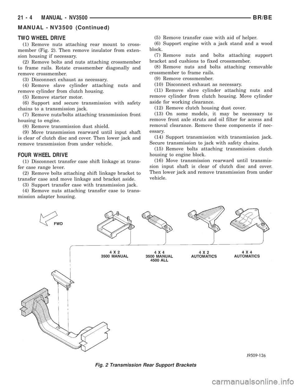
TWO WHEEL DRIVE
(1) Remove nuts attaching rear mount to cross-
member (Fig. 2). Then remove insulator from exten-
sion housing if necessary.
(2) Remove bolts and nuts attaching crossmember
to frame rails. Rotate crossmember diagonally and
remove crossmember.
(3) Disconnect exhaust as necessary.
(4) Remove slave cylinder attaching nuts and
remove cylinder from clutch housing.
(5) Remove starter motor.
(6) Support and secure transmission with safety
chains to a transmission jack.
(7) Remove nuts/bolts attaching transmission front
housing to engine.
(8) Remove transmission dust shield.
(9) Move transmission rearward until input shaft
is clear of clutch disc and cover. Then lower jack and
remove transmission from under vehicle.
FOUR WHEEL DRIVE
(1) Disconnect transfer case shift linkage at trans-
fer case range lever.
(2) Remove bolts attaching shift linkage bracket to
transfer case and move linkage and bracket aside.
(3) Support transfer case with transmission jack.
(4) Remove nuts attaching transfer case to trans-
mission adapter housing.(5) Remove transfer case with aid of helper.
(6) Support engine with a jack stand and a wood
block.
(7) Remove nuts and bolts attaching support
bracket and cushions to fixed crossmember.
(8) Remove nuts and bolts attaching removable
crossmember to frame rails.
(9) Remove crossmember.
(10) Disconnect exhaust as necessary.
(11) Remove slave cylinder attaching nuts and
remove cylinder from clutch housing. Move cylinder
aside for working clearance.
(12) Remove clutch housing dust cover.
(13) On some models, it may be necessary to
remove front axle struts and oil filter for access and
removal clearance. Remove these components if nec-
essary.
(14) Support transmission with transmission jack.
Secure transmission to jack with safety chains.
(15) Remove bolts attaching transmission clutch
housing to engine block.
(16) Move transmission rearward until transmis-
sion input shaft is clear of clutch disc and cover.
Then lower jack and remove transmission from under
vehicle.
Fig. 2 Transmission Rear Support Brackets
21 - 4 MANUAL - NV3500BR/BE
MANUAL - NV3500 (Continued)
Page 1652 of 2889
Inspect the input shaft bearing retainer. Be sure
the release bearing slide surface of the retainer is in
good condition. Minor nicks on the surface can be
smoothed off with 320/420 grit emery cloth and final
polished with oil coated crocus cloth. Replace the
retainer seal if necessary.
Inspect the output shaft bearing retainer. Be sure
the U-shaped retainer is flat and free of distortion.
Replace the retainer if the threads are damaged, or if
the retainer is bent, or cracked.
COUNTERSHAFT BEARINGS AND RACES
The countershaft bearings and races are machine
lapped during manufacture to form matched sets.
The bearings and races should not be interchanged.
NOTE: The bearing races are a permanent press fit
in the housings and are NOT serviceable. If a bear-
ing race becomes damaged, it will be necessary to
replace the front or rear housing as necessary. A
new countershaft bearing will be supplied with each
new housing for service use.
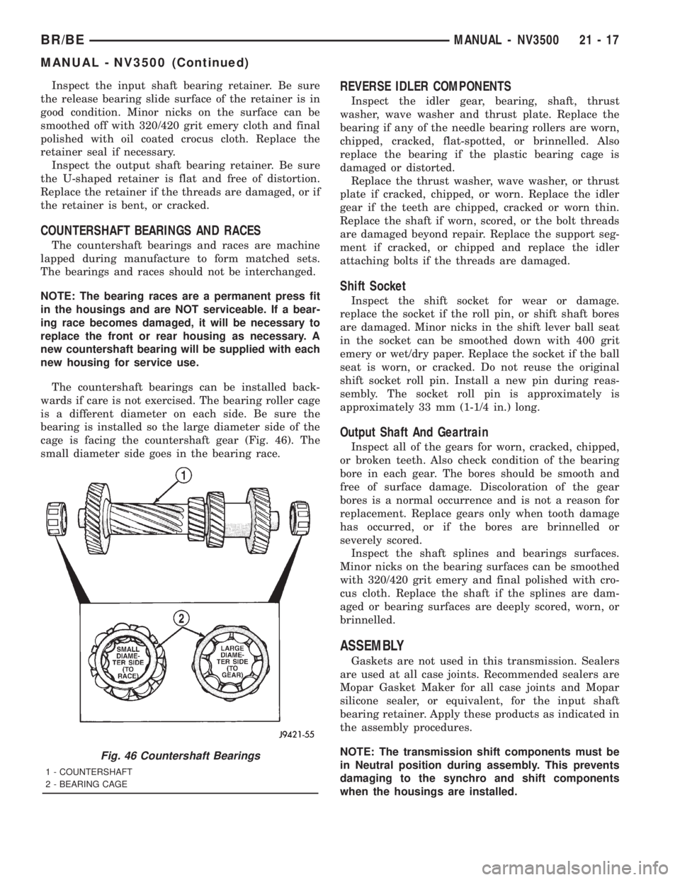
The countershaft bearings can be installed back-
wards if care is not exercised. The bearing roller cage
is a different diameter on each side. Be sure the
bearing is installed so the large diameter side of the
cage is facing the countershaft gear (Fig. 46). The
small diameter side goes in the bearing race.
REVERSE IDLER COMPONENTS
Inspect the idler gear, bearing, shaft, thrust
washer, wave washer and thrust plate. Replace the
bearing if any of the needle bearing rollers are worn,
chipped, cracked, flat-spotted, or brinnelled. Also
replace the bearing if the plastic bearing cage is
damaged or distorted.
Replace the thrust washer, wave washer, or thrust
plate if cracked, chipped, or worn. Replace the idler
gear if the teeth are chipped, cracked or worn thin.
Replace the shaft if worn, scored, or the bolt threads
are damaged beyond repair. Replace the support seg-
ment if cracked, or chipped and replace the idler
attaching bolts if the threads are damaged.
Shift Socket
Inspect the shift socket for wear or damage.
replace the socket if the roll pin, or shift shaft bores
are damaged. Minor nicks in the shift lever ball seat
in the socket can be smoothed down with 400 grit
emery or wet/dry paper. Replace the socket if the ball
seat is worn, or cracked. Do not reuse the original
shift socket roll pin. Install a new pin during reas-
sembly. The socket roll pin is approximately is
approximately 33 mm (1-1/4 in.) long.
Output Shaft And Geartrain
Inspect all of the gears for worn, cracked, chipped,
or broken teeth. Also check condition of the bearing
bore in each gear. The bores should be smooth and
free of surface damage. Discoloration of the gear
bores is a normal occurrence and is not a reason for
replacement. Replace gears only when tooth damage
has occurred, or if the bores are brinnelled or
severely scored.
Inspect the shaft splines and bearings surfaces.
Minor nicks on the bearing surfaces can be smoothed
with 320/420 grit emery and final polished with cro-
cus cloth. Replace the shaft if the splines are dam-
aged or bearing surfaces are deeply scored, worn, or
brinnelled.
ASSEMBLY
Gaskets are not used in this transmission. Sealers
are used at all case joints. Recommended sealers are
Mopar Gasket Maker for all case joints and Mopar
silicone sealer, or equivalent, for the input shaft
bearing retainer. Apply these products as indicated in
the assembly procedures.
NOTE: The transmission shift components must be
in Neutral position during assembly. This prevents
damaging to the synchro and shift components
when the housings are installed.
Fig. 46 Countershaft Bearings
1 - COUNTERSHAFT
2 - BEARING CAGE
BR/BEMANUAL - NV3500 21 - 17
MANUAL - NV3500 (Continued)
Page 1662 of 2889
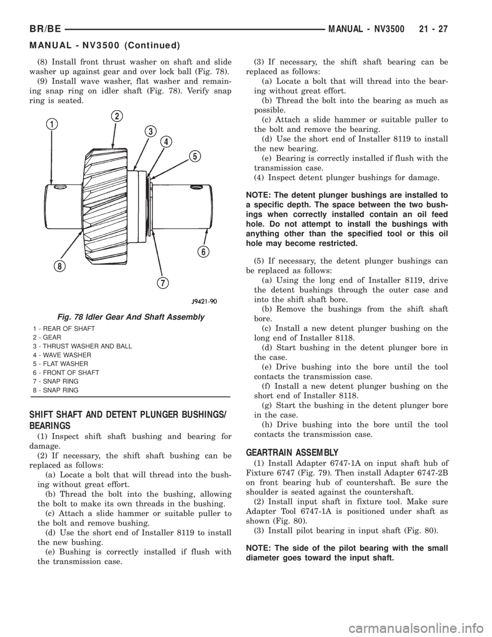
(8) Install front thrust washer on shaft and slide
washer up against gear and over lock ball (Fig. 78).
(9) Install wave washer, flat washer and remain-
ing snap ring on idler shaft (Fig. 78). Verify snap
ring is seated.
SHIFT SHAFT AND DETENT PLUNGER BUSHINGS/
BEARINGS
(1) Inspect shift shaft bushing and bearing for
damage.
(2) If necessary, the shift shaft bushing can be
replaced as follows:
(a) Locate a bolt that will thread into the bush-
ing without great effort.
(b) Thread the bolt into the bushing, allowing
the bolt to make its own threads in the bushing.
(c) Attach a slide hammer or suitable puller to
the bolt and remove bushing.
(d) Use the short end of Installer 8119 to install
the new bushing.
(e) Bushing is correctly installed if flush with
the transmission case.(3) If necessary, the shift shaft bearing can be
replaced as follows:
(a) Locate a bolt that will thread into the bear-
ing without great effort.
(b) Thread the bolt into the bearing as much as
possible.
(c) Attach a slide hammer or suitable puller to
the bolt and remove the bearing.
(d) Use the short end of Installer 8119 to install
the new bearing.
(e) Bearing is correctly installed if flush with the
transmission case.
(4) Inspect detent plunger bushings for damage.
NOTE: The detent plunger bushings are installed to
a specific depth. The space between the two bush-
ings when correctly installed contain an oil feed
hole. Do not attempt to install the bushings with
anything other than the specified tool or this oil
hole may become restricted.
(5) If necessary, the detent plunger bushings can
be replaced as follows:
(a) Using the long end of Installer 8119, drive
the detent bushings through the outer case and
into the shift shaft bore.
(b) Remove the bushings from the shift shaft
bore.
(c) Install a new detent plunger bushing on the
long end of Installer 8118.
(d) Start bushing in the detent plunger bore in
the case.
(e) Drive bushing into the bore until the tool
contacts the transmission case.
(f) Install a new detent plunger bushing on the
short end of Installer 8118.
(g) Start the bushing in the detent plunger bore
in the case.
(h) Drive bushing into the bore until the tool
contacts the transmission case.
GEARTRAIN ASSEMBLY
(1) Install Adapter 6747-1A on input shaft hub of
Fixture 6747 (Fig. 79). Then install Adapter 6747-2B
on front bearing hub of countershaft. Be sure the
shoulder is seated against the countershaft.
(2) Install input shaft in fixture tool. Make sure
Adapter Tool 6747-1A is positioned under shaft as
shown (Fig. 80).
(3) Install pilot bearing in input shaft (Fig. 80).
NOTE: The side of the pilot bearing with the small
diameter goes toward the input shaft.
Fig. 78 Idler Gear And Shaft Assembly
1 - REAR OF SHAFT
2 - GEAR
3 - THRUST WASHER AND BALL
4 - WAVE WASHER
5 - FLAT WASHER
6 - FRONT OF SHAFT
7 - SNAP RING
8 - SNAP RING
BR/BEMANUAL - NV3500 21 - 27
MANUAL - NV3500 (Continued)