2001 DODGE RAM steering
[x] Cancel search: steeringPage 534 of 2889
INSTALLATION
(1) Position the horn and mounting bracket unit(s)
onto the right fender wheel house front extension.
(2) Install and tighten the screw that secures the
horn and mounting bracket unit(s) to the right
fender wheel house front extension. Tighten the
screw to 11 N´m (95 in. lbs.).
(3) Reconnect the wire harness connector(s) to the
horn connector receptacle(s).
(4) Reconnect the battery negative cable.
HORN RELAY
DESCRIPTION
The horn relay is a electromechanical device that
switches battery current to the horn when the horn
switch grounds the relay coil. The horn relay is
located in the Power Distribution Center (PDC) in
the engine compartment. If a problem is encountered
with a continuously sounding horn, it can usually be
quickly resolved by removing the horn relay from the
PDC until further diagnosis is completed. See the
fuse and relay layout label affixed to the inside sur-
face of the PDC cover for horn relay identification
and location.
The horn relay is a International Standards Orga-
nization (ISO) micro-relay. Relays conforming to the
ISO specifications have common physical dimensions,
current capacities, terminal patterns, and terminal
functions. The ISO micro-relay terminal functions
are the same as a conventional ISO relay. However,
the ISO micro-relay terminal pattern (or footprint) is
different, the current capacity is lower, and the phys-
ical dimensions are smaller than those of the conven-
tional ISO relay.
The horn relay cannot be repaired or adjusted and,
if faulty or damaged, it must be replaced.
OPERATION
The ISO relay consists of an electromagnetic coil, a
resistor or diode, and three (two fixed and one mov-
able) electrical contacts. The movable (common feed)
relay contact is held against one of the fixed contacts
(normally closed) by spring pressure. When the elec-
tromagnetic coil is energized, it draws the movable
contact away from the normally closed fixed contact,
and holds it against the other (normally open) fixed
contact.
When the electromagnetic coil is de-energized,
spring pressure returns the movable contact to the
normally closed position. The resistor or diode is con-
nected in parallel with the electromagnetic coil in the
relay, and helps to dissipate voltage spikes that are
produced when the coil is de-energized.
DIAGNOSIS AND TESTING
DIAGNOSIS AND TESTING - HORN RELAY
The horn relay (Fig. 2) is located in the Power Dis-
tribution Center (PDC) behind the battery on the
driver side of the engine compartment. If a problem
is encountered with a continuously sounding horn, it
can usually be quickly resolved by removing the horn
relay from the PDC until further diagnosis is com-
pleted. See the fuse and relay layout label affixed to
the inside surface of the PDC cover for horn relay
identification and location. For complete circuit dia-
grams, refer to the appropriate wiring information.
The wiring information includes wiring diagrams,
proper wire and connector repair procedures, details
of wire harness routing and retention, connector pin-
out information and location views for the various
wire harness connectors, splices and grounds.
WARNING: ON VEHICLES EQUIPPED WITH AIR-
BAGS, REFER TO ELECTRICAL, RESTRAINTS
BEFORE ATTEMPTING ANY STEERING WHEEL,
STEERING COLUMN, OR INSTRUMENT PANEL
COMPONENT DIAGNOSIS OR SERVICE. FAILURE
TO TAKE THE PROPER PRECAUTIONS COULD
RESULT IN ACCIDENTAL AIRBAG DEPLOYMENT
AND POSSIBLE PERSONAL INJURY.
(1) Remove the horn relay from the PDC. (Refer to
8 - ELECTRICAL/HORN/HORN RELAY -
REMOVAL) for the procedures.
(2) A relay in the de-energized position should
have continuity between terminals 87A and 30, and
no continuity between terminals 87 and 30. If OK, go
to Step 3. If not OK, replace the faulty relay.
(3) Resistance between terminals 85 and 86 (elec-
tromagnet) should be 7565 ohms. If OK, go to Step
4. If not OK, replace the faulty relay.
(4) Connect a battery to terminals 85 and 86.
There should now be continuity between terminals
30 and 87, and no continuity between terminals 87A
and 30. If OK, perform the Relay Circuit Test that
follows. If not OK, replace the faulty relay.
RELAY CIRCUIT TEST
(1) The relay common feed terminal cavity (30) is
connected to battery voltage and should be hot at all
times. If OK, go to Step 2. If not OK, repair the open
circuit to the fuse in the PDC as required.
(2) The relay normally closed terminal (87A) is
connected to terminal 30 in the de-energized position,
but is not used for this application. Go to Step 3.
BR/BEHORN 8H - 3
HORN (Continued)
Page 535 of 2889
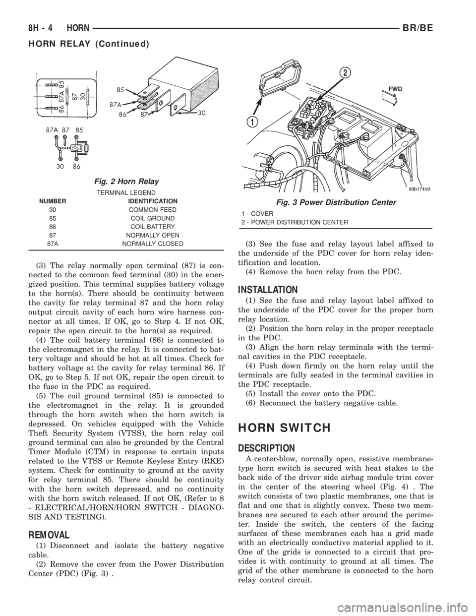
(3) The relay normally open terminal (87) is con-
nected to the common feed terminal (30) in the ener-
gized position. This terminal supplies battery voltage
to the horn(s). There should be continuity between
the cavity for relay terminal 87 and the horn relay
output circuit cavity of each horn wire harness con-
nector at all times. If OK, go to Step 4. If not OK,
repair the open circuit to the horn(s) as required.
(4) The coil battery terminal (86) is connected to
the electromagnet in the relay. It is connected to bat-
tery voltage and should be hot at all times. Check for
battery voltage at the cavity for relay terminal 86. If
OK, go to Step 5. If not OK, repair the open circuit to
the fuse in the PDC as required.
(5) The coil ground terminal (85) is connected to
the electromagnet in the relay. It is grounded
through the horn switch when the horn switch is
depressed. On vehicles equipped with the Vehicle
Theft Security System (VTSS), the horn relay coil
ground terminal can also be grounded by the Central
Timer Module (CTM) in response to certain inputs
related to the VTSS or Remote Keyless Entry (RKE)
system. Check for continuity to ground at the cavity
for relay terminal 85. There should be continuity
with the horn switch depressed, and no continuity
with the horn switch released. If not OK, (Refer to 8
- ELECTRICAL/HORN/HORN SWITCH - DIAGNO-
SIS AND TESTING).
REMOVAL
(1) Disconnect and isolate the battery negative
cable.
(2) Remove the cover from the Power Distribution
Center (PDC) (Fig. 3) .(3) See the fuse and relay layout label affixed to
the underside of the PDC cover for horn relay iden-
tification and location.
(4) Remove the horn relay from the PDC.
INSTALLATION
(1) See the fuse and relay layout label affixed to
the underside of the PDC cover for the proper horn
relay location.
(2) Position the horn relay in the proper receptacle
in the PDC.
(3) Align the horn relay terminals with the termi-
nal cavities in the PDC receptacle.
(4) Push down firmly on the horn relay until the
terminals are fully seated in the terminal cavities in
the PDC receptacle.
(5) Install the cover onto the PDC.
(6) Reconnect the battery negative cable.
HORN SWITCH
DESCRIPTION
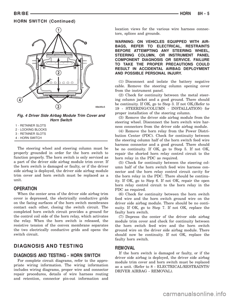
A center-blow, normally open, resistive membrane-
type horn switch is secured with heat stakes to the
back side of the driver side airbag module trim cover
in the center of the steering wheel (Fig. 4) . The
switch consists of two plastic membranes, one that is
flat and one that is slightly convex. These two mem-
branes are secured to each other around the perime-
ter. Inside the switch, the centers of the facing
surfaces of these membranes each has a grid made
with an electrically conductive material applied to it.
One of the grids is connected to a circuit that pro-
vides it with continuity to ground at all times. The
grid of the other membrane is connected to the horn
relay control circuit.
Fig. 2 Horn Relay
TERMINAL LEGEND
NUMBER IDENTIFICATION
30 COMMON FEED
85 COIL GROUND
86 COIL BATTERY
87 NORMALLY OPEN
87A NORMALLY CLOSED
Fig. 3 Power Distribution Center
1 - COVER
2 - POWER DISTRIBUTION CENTER
8H - 4 HORNBR/BE
HORN RELAY (Continued)
Page 536 of 2889
The steering wheel and steering column must be
properly grounded in order for the horn switch to
function properly. The horn switch is only serviced as
a part of the driver side airbag module trim cover. If
the horn switch is damaged or faulty, or if the driver
side airbag is deployed, the driver side airbag module
trim cover and horn switch must be replaced as a
unit.
OPERATION
When the center area of the driver side airbag trim
cover is depressed, the electrically conductive grids
on the facing surfaces of the horn switch membranes
contact each other, closing the switch circuit. The
completed horn switch circuit provides a ground for
the control coil side of the horn relay, which activates
the relay. When the horn switch is released, the
resistive tension of the convex membrane separates
the two electrically conductive grids and opens the
switch circuit.
DIAGNOSIS AND TESTING
DIAGNOSIS AND TESTING - HORN SWITCH
For complete circuit diagrams, refer to the appro-
priate wiring information. The wiring information
includes wiring diagrams, proper wire and connector
repair procedures, details of wire harness routing
and retention, connector pin-out information andlocation views for the various wire harness connec-
tors, splices and grounds.
WARNING: ON VEHICLES EQUIPPED WITH AIR-
BAGS, REFER TO ELECTRICAL, RESTRAINTS
BEFORE ATTEMPTING ANY STEERING WHEEL,
STEERING COLUMN, OR INSTRUMENT PANEL
COMPONENT DIAGNOSIS OR SERVICE. FAILURE
TO TAKE THE PROPER PRECAUTIONS COULD
RESULT IN ACCIDENTAL AIRBAG DEPLOYMENT
AND POSSIBLE PERSONAL INJURY.
(1) Disconnect and isolate the battery negative
cable. Remove the steering column opening cover
from the instrument panel.
(2) Check for continuity between the metal steer-
ing column jacket and a good ground. There should
be continuity. If OK, go to Step 3. If not OK,(Refer to
19 - STEERING/COLUMN - INSTALLATION) for
proper installation of the steering column.
(3) Remove the driver side airbag module from the
steering wheel. Disconnect the horn switch wire har-
ness connectors from the driver side airbag module.
(4) Remove the horn relay from the Power Distri-
bution Center (PDC). Check for continuity between
the steering column half of the horn switch feed wire
harness connector and a good ground. There should
be no continuity. If OK, go to Step 5. If not OK,
repair the shorted horn relay control circuit to the
horn relay in the PDC as required.
(5) Check for continuity between the steering col-
umn half of the horn switch feed wire harness con-
nector and the horn relay control circuit cavity for
the horn relay in the PDC. There should be continu-
ity. If OK, go to Step 6. If not OK, repair the open
horn relay control circuit to the horn relay in the
PDC as required.
(6) Check for continuity between the horn switch
feed wire and the horn switch ground wire on the
driver side airbag module. There should be no conti-
nuity. If OK, go to Step 7. If not OK, replace the
faulty horn switch.
(7) Depress the center of the driver side airbag
module trim cover and check for continuity between
the horn switch feed wire and the horn switch
ground wire on the driver side airbag module. There
should now be continuity. If not OK, replace the
faulty horn switch.
REMOVAL
If the horn switch is damaged or faulty, or if the
driver side airbag is deployed, the driver side airbag
module trim cover and horn switch must be replaced
as a unit. (Refer to 8 - ELECTRICAL/RESTRAINTS/
DRIVER AIRBAG - REMOVAL).
Fig. 4 Driver Side Airbag Module Trim Cover and
Horn Switch
1 - RETAINER SLOTS
2 - LOCKING BLOCKS
3 - RETAINER SLOTS
4 - HORN SWITCH
BR/BEHORN 8H - 5
HORN SWITCH (Continued)
Page 549 of 2889

removed). Then continue to slowly rotate engine
clockwise until indicating mark (Fig. 18) is aligned to
0 degree (TDC) mark on timing chain cover.
(1) Clean top of cylinder block for a good seal
between distributor base and block.
(2) Lightly oil the rubber o-ring seal on the distrib-
utor housing.
(3) Install rotor to distributor shaft.
(4) Position distributor into engine to its original
position. Engage tongue of distributor shaft with slot
in distributor oil pump drive gear. Position rotor to
the number one spark plug cable position.
(5) Install distributor holddown clamp and clamp
bolt. Do not tighten bolt at this time.(6) Rotate the distributor housing until rotor is
aligned to CYL. NO. 1 alignment mark on the cam-
shaft position sensor (Fig. 19) .
(7) Tighten clamp holddown bolt (Fig. 20) to 22.5
N´m (200 in. lbs.) torque.
(8) Connect camshaft position sensor wiring har-
ness to main engine harness.
(9) Install distributor cap. Tighten mounting
screws.
(10) Refer to the following, Checking Distributor
Position.
Checking Distributor Position
To verify correct distributor rotational position, the
DRB scan tool must be used.
WARNING: WHEN PERFORMING THE FOLLOWING
TEST, THE ENGINE WILL BE RUNNING. BE CARE-
FUL NOT TO STAND IN LINE WITH THE FAN
BLADES OR FAN BELT. DO NOT WEAR LOOSE
CLOTHING.
(1) Connect DRB scan tool to data link connector.
The data link connector is located in passenger com-
partment, below and to left of steering column.
(2) Gain access to SET SYNC screen on DRB.
(3) Follow directions on DRB screen and start
engine. Bring to operating temperature (engine must
be in ªclosed loopº mode).
(4) With engine running atidle speed, the words
IN RANGE should appear on screen along with 0É.
This indicates correct distributor position.
(5) If a plus (+) or a minus (-) is displayed next to
degree number, and/or the degree displayed is not
zero, loosen but do not remove distributor holddown
clamp bolt. Rotate distributor until IN RANGE
appears on screen. Continue to rotate distributor
until achieving as close to 0É as possible. After
adjustment, tighten clamp bolt to 22.5 N´m (200 in.
lbs.) torque.
The degree scale on SET SYNC screen of DRB is
referring to fuel synchronization only.It is not
referring to ignition timing.Because of this, do
not attempt to adjust ignition timing using this
method. Rotating distributor will have no effect on
ignition timing. All ignition timing values are con-
trolled by powertrain control module (PCM).
After testing, install air cleaner assembly.
DISTRIBUTOR CAP
DIAGNOSIS AND TESTING - DISTRIBUTOR
CAP
Remove the distributor cap and wipe it clean with
a dry lint free cloth. Visually inspect the cap for
cracks, carbon paths, broken towers or damaged
Fig. 19 Rotor Alignment Mark
1 - CAMSHAFT POSITION SENSOR ALIGNMENT MARK
2 - ROTOR
3 - DISTRIBUTOR
Fig. 20 Distributor Holddown Clamp
1 - CLAMP BOLT
2 - HOLDDOWN CLAMP
3 - DISTRIBUTOR HOUSING
8I - 12 IGNITION CONTROLBR/BE
DISTRIBUTOR (Continued)
Page 561 of 2889
INSTRUMENT CLUSTER
DESCRIPTION
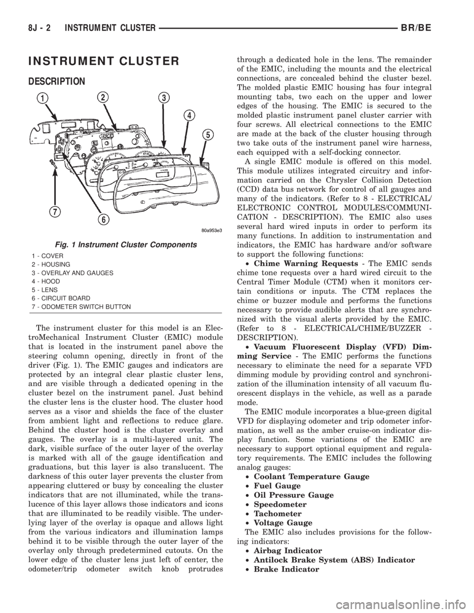
The instrument cluster for this model is an Elec-
troMechanical Instrument Cluster (EMIC) module
that is located in the instrument panel above the
steering column opening, directly in front of the
driver (Fig. 1). The EMIC gauges and indicators are
protected by an integral clear plastic cluster lens,
and are visible through a dedicated opening in the
cluster bezel on the instrument panel. Just behind
the cluster lens is the cluster hood. The cluster hood
serves as a visor and shields the face of the cluster
from ambient light and reflections to reduce glare.
Behind the cluster hood is the cluster overlay and
gauges. The overlay is a multi-layered unit. The
dark, visible surface of the outer layer of the overlay
is marked with all of the gauge identification and
graduations, but this layer is also translucent. The
darkness of this outer layer prevents the cluster from
appearing cluttered or busy by concealing the cluster
indicators that are not illuminated, while the trans-
lucence of this layer allows those indicators and icons
that are illuminated to be readily visible. The under-
lying layer of the overlay is opaque and allows light
from the various indicators and illumination lamps
behind it to be visible through the outer layer of the
overlay only through predetermined cutouts. On the
lower edge of the cluster lens just left of center, the
odometer/trip odometer switch knob protrudesthrough a dedicated hole in the lens. The remainder
of the EMIC, including the mounts and the electrical
connections, are concealed behind the cluster bezel.
The molded plastic EMIC housing has four integral
mounting tabs, two each on the upper and lower
edges of the housing. The EMIC is secured to the
molded plastic instrument panel cluster carrier with
four screws. All electrical connections to the EMIC
are made at the back of the cluster housing through
two take outs of the instrument panel wire harness,
each equipped with a self-docking connector.
A single EMIC module is offered on this model.
This module utilizes integrated circuitry and infor-
mation carried on the Chrysler Collision Detection
(CCD) data bus network for control of all gauges and
many of the indicators. (Refer to 8 - ELECTRICAL/
ELECTRONIC CONTROL MODULES/COMMUNI-
CATION - DESCRIPTION). The EMIC also uses
several hard wired inputs in order to perform its
many functions. In addition to instrumentation and
indicators, the EMIC has hardware and/or software
to support the following functions:
²Chime Warning Requests- The EMIC sends
chime tone requests over a hard wired circuit to the
Central Timer Module (CTM) when it monitors cer-
tain conditions or inputs. The CTM replaces the
chime or buzzer module and performs the functions
necessary to provide audible alerts that are synchro-
nized with the visual alerts provided by the EMIC.
(Refer to 8 - ELECTRICAL/CHIME/BUZZER -
DESCRIPTION).
²Vacuum Fluorescent Display (VFD) Dim-
ming Service- The EMIC performs the functions
necessary to eliminate the need for a separate VFD
dimming module by providing control and synchroni-
zation of the illumination intensity of all vacuum flu-
orescent displays in the vehicle, as well as a parade
mode.
The EMIC module incorporates a blue-green digital
VFD for displaying odometer and trip odometer infor-
mation, as well as the amber cruise-on indicator dis-
play function. Some variations of the EMIC are
necessary to support optional equipment and regula-
tory requirements. The EMIC includes the following
analog gauges:
²Coolant Temperature Gauge
²Fuel Gauge
²Oil Pressure Gauge
²Speedometer
²Tachometer
²Voltage Gauge
The EMIC also includes provisions for the follow-
ing indicators:
²Airbag Indicator
²Antilock Brake System (ABS) Indicator
²Brake Indicator
Fig. 1 Instrument Cluster Components
1 - COVER
2 - HOUSING
3 - OVERLAY AND GAUGES
4 - HOOD
5 - LENS
6 - CIRCUIT BOARD
7 - ODOMETER SWITCH BUTTON
8J - 2 INSTRUMENT CLUSTERBR/BE
Page 563 of 2889
The EMIC circuitry operates on battery current
received through a fused B(+) fuse in the Junction
Block (JB) on a non-switched fused B(+) circuit, and
on battery current received through a fused ignition
switch output (st-run) fuse in the JB on a fused igni-
tion switch output (st-run) circuit. This arrangement
allows the EMIC to provide some features regardless
of the ignition switch position, while other features
will operate only with the ignition switch in the Start
or On positions. The EMIC circuitry is grounded
through two separate ground circuits located in one
of the two instrument cluster connectors and take
outs of the instrument panel wire harness. One
ground circuit receives ground through a take out
with an eyelet terminal connector of the instrument
panel wire harness that is secured by a nut to a
ground stud located on the left instrument panel end
bracket, while the other ground circuit receives
ground through a take out with an eyelet terminal
connector of the instrument panel wire harness that
is secured by a nut to a ground stud located on the
back of the instrument panel armature above the
inboard side of the instrument panel steering column
opening.
The EMIC also has a self-diagnostic actuator test
capability, which will test each of the CCD bus mes-
sage-controlled functions of the cluster by lighting
the appropriate indicators and positioning the gauge
needles at several predetermined locations on the
gauge faces in a prescribed sequence. (Refer to 8 -
ELECTRICAL/INSTRUMENT CLUSTER - DIAGNO-
SIS AND TESTING). See the owner's manual in the
vehicle glove box for more information on the fea-
tures, use and operation of the EMIC.
GAUGES
All gauges receive battery current through the
EMIC circuitry when the ignition switch is in the On
or Start positions. With the ignition switch in the Off
position battery current is not supplied to any
gauges, and the EMIC circuitry is programmed to
move all of the gauge needles back to the low end of
their respective scales. Therefore, the gauges do not
accurately indicate any vehicle condition unless the
ignition switch is in the On or Start positions. All of
the EMIC gauges, except the odometer, are air core
magnetic units. Two fixed electromagnetic coils are
located within each gauge. These coils are wrapped
at right angles to each other around a movable per-
manent magnet. The movable magnet is suspended
within the coils on one end of a pivot shaft, while the
gauge needle is attached to the other end of the
shaft. One of the coils has a fixed current flowing
through it to maintain a constant magnetic fieldstrength. Current flow through the second coil
changes, which causes changes in its magnetic field
strength. The current flowing through the second coil
is changed by the EMIC circuitry in response to mes-
sages received over the CCD data bus. The gauge
needle moves as the movable permanent magnet
aligns itself to the changing magnetic fields created
around it by the electromagnets.
The gauges are diagnosed using the EMIC self-di-
agnostic actuator test. (Refer to 8 - ELECTRICAL/
INSTRUMENT CLUSTER - DIAGNOSIS AND
TESTING). Proper testing of the CCD data bus and
the data bus message inputs to the EMIC that con-
trol each gauge require the use of a DRBIIItscan
tool. Refer to the appropriate diagnostic information.
Specific operation details for each gauge may be
found elsewhere in this service manual.
VACUUM-FLUORESCENT DISPLAY
The Vacuum-Fluorescent Display (VFD) module is
soldered to the EMIC circuit board. The display is
active with the ignition switch in the On or Start
positions, and inactive when the ignition switch is in
any other position. The VFD has several display
capabilities including odometer, trip odometer, and
an amber ªCRUISEº indication whenever the
optional speed control system is turned On. The
cruise indicator function of the VFD is automatically
enabled or disabled by the EMIC circuitry based
upon whether the vehicle is equipped with the speed
control option. An odometer/trip odometer switch on
the EMIC circuit board is used to control several of
the display modes. This switch is actuated manually
by depressing the odometer/trip odometer switch
knob that extends through the lower edge of the clus-
ter lens, just right of center. Actuating this switch
momentarily with the ignition switch in the On posi-
tion will toggle the VFD between the odometer and
trip odometer modes. The word ªTRIPº will also
appear in blue-green text when the VFD trip odome-
ter mode is active. Depressing the switch button for
about two seconds while the VFD is in the trip odom-
eter mode will reset the trip odometer value to zero.
Holding this switch depressed while turning the igni-
tion switch from the Off position to the On position
will activate the EMIC self-diagnostic actuator test.
The EMIC will automatically flash the odometer or
trip odometer information on and off if there is a loss
of CCD data bus communication. The VFD will also
display various information used in several diagnos-
tic procedures. Refer to the appropriate diagnostic
information for additional details on this VFD func-
tion.
8J - 4 INSTRUMENT CLUSTERBR/BE
INSTRUMENT CLUSTER (Continued)
Page 565 of 2889
CHIME WARNING REQUESTS
The EMIC is programmed to request chime service
from the Central Timer Module (CTM) when certain
indicator lamps are illuminated. When the pro-
grammed conditions are met, the EMIC generates a
chime request signal and sends it over a hard wired
tone request circuit to the CTM. Upon receiving the
proper chime request, the CTM activates an integral
chime tone generator to provide the audible chime
tone to the vehicle operator. (Refer to 8 - ELECTRI-
CAL/CHIME/BUZZER - OPERATION). Proper test-
ing of the CTM and the EMIC chime requests
requires the use of a DRBIIItscan tool. Refer to the
appropriate diagnostic information.
DIAGNOSIS AND TESTING - INSTRUMENT
CLUSTER
If all of the instrument cluster gauges and/or indi-
cators are inoperative, refer to PRELIMINARY
DIAGNOSIS . If an individual gauge or Chrysler Col-
lision Detection (CCD) data bus message-controlled
indicator is inoperative, refer to ACTUATOR TEST .
If an individual hard wired indicator is inoperative,
refer to the diagnosis and testing information for
that specific indicator. If the instrument cluster
chime warning request function is inoperative, refer
to CHIME WARNING REQUEST DIAGNOSIS . If
the instrument cluster illumination lighting is inop-
erative, refer to CLUSTER ILLUMINATION DIAG-
NOSIS . If the instrument cluster Vacuum-
Fluorescent Display (VFD) dimmer service is
inoperative, use a DRBIIItscan tool to diagnose the
problem. Refer to the appropriate diagnostic proce-
dures. Refer to the appropriate wiring information.
The wiring information includes wiring diagrams,
proper wire and connector repair procedures, details
of wire harness routing and retention, connector pin-
out information and location views for the various
wire harness connectors, splices and grounds.
NOTE: Certain indicators in this instrument cluster
are programmable. This feature allows those indica-
tors to be activated or deactivated with a DRBIIIT
scan tool for compatibility with certain optional
equipment. If the problem being diagnosed involves
improper illumination of the upshift indicator, use a
DRBIIITscan tool to be certain that the instrument
cluster has been programmed with the proper vehi-
cle equipment option settings.PRELIMINARY DIAGNOSIS
WARNING: ON VEHICLES EQUIPPED WITH AIR-
BAGS, DISABLE THE AIRBAG SYSTEM BEFORE
ATTEMPTING ANY STEERING WHEEL, STEERING
COLUMN, OR INSTRUMENT PANEL COMPONENT
DIAGNOSIS OR SERVICE. DISCONNECT AND ISO-
LATE THE BATTERY NEGATIVE (GROUND) CABLE,
THEN WAIT TWO MINUTES FOR THE AIRBAG SYS-
TEM CAPACITOR TO DISCHARGE BEFORE PER-
FORMING FURTHER DIAGNOSIS OR SERVICE. THIS
IS THE ONLY SURE WAY TO DISABLE THE AIRBAG
SYSTEM. FAILURE TO TAKE THE PROPER PRE-
CAUTIONS COULD RESULT IN ACCIDENTAL AIR-
BAG DEPLOYMENT AND POSSIBLE PERSONAL
INJURY.
(1) If the indicators operate, but none of the
gauges operate, go to Step 2. If all of the gauges and
the CCD data bus message-controlled indicators are
inoperative, go to Step 5.
(2) Check the fused B(+) fuse (Fuse 14 - 10
ampere) in the Junction Block (JB). If OK, go to Step
3. If not OK, repair the shorted circuit or component
as required and replace the faulty fuse.
(3) Check for battery voltage at the fused B(+) fuse
(Fuse 14 - 10 ampere) in the JB. If OK, go to Step 4.
If not OK, repair the open fused B(+) circuit between
the JB and the Power Distribution Center (PDC) as
required.
(4) Disconnect and isolate the battery negative
cable. Remove the instrument cluster. Connect the
battery negative cable. Check for battery voltage at
the fused B(+) circuit cavity of the instrument panel
wire harness connector (Connector C1) for the instru-
ment cluster. If OK, refer to ACTUATOR TEST . If
not OK, repair the open fused B(+) circuit between
the instrument cluster and the JB as required.
(5) Check the fused ignition switch output (st-run)
fuse (Fuse 17 - 10 ampere) in the JB. If OK, go to
Step 6. If not OK, repair the shorted circuit or com-
ponent as required and replace the faulty fuse.
(6) Turn the ignition switch to the On position.
Check for battery voltage at the fused ignition switch
output (st-run) fuse (Fuse 17 - 10 ampere) in the JB.
If OK, go to Step 7. If not OK, repair the open fused
ignition switch output (st-run) circuit between the
instrument cluster and the JB as required.
8J - 6 INSTRUMENT CLUSTERBR/BE
INSTRUMENT CLUSTER (Continued)
Page 566 of 2889

(7) Turn the ignition switch to the Off position.
Disconnect and isolate the battery negative cable.
Reinstall the instrument cluster. Reconnect the bat-
tery negative cable. Turn the ignition switch to the
On position. Set the park brake. The brake indicator
in the instrument cluster should light. If OK, go to
Step 8. If not OK, go to Step 9.
(8) Turn the ignition switch to the Off position.
Turn on the park lamps and adjust the panel lamps
dimmer thumbwheel in the headlamp switch to the
full bright position. The cluster illumination lamps
should light. If OK, go to Step 10. If not OK, repair
the open ground circuit (Z3) between the instrument
cluster and ground (G201) as required.
(9) Turn the ignition switch to the Off position.
Disconnect and isolate the battery negative cable.
Remove the instrument cluster. Connect the battery
negative cable. Turn the ignition switch to the On
position. Check for battery voltage at the fused igni-
tion switch output (st-run) circuit cavity of the
instrument panel wire harness connector (Connector
C1). If OK, refer to ACTUATOR TEST . If not OK,
repair the open fused ignition switch output (st-run)
circuit between the instrument cluster and the JB as
required.
(10) Disconnect and isolate the battery negative
cable. Remove the instrument cluster. Check for con-
tinuity between the ground circuit (Z2) cavity of the
instrument panel wire harness connector (Connector
C1) and a good ground. There should be continuity. If
OK, refer to ACTUATOR TEST . If not OK, repair
the open ground circuit to ground (G200) as required.
ACTUATOR TEST
WARNING: ON VEHICLES EQUIPPED WITH AIR-
BAGS, DISABLE THE AIRBAG SYSTEM BEFORE
ATTEMPTING ANY STEERING WHEEL, STEERING
COLUMN, OR INSTRUMENT PANEL COMPONENT
DIAGNOSIS OR SERVICE. DISCONNECT AND ISO-
LATE THE BATTERY NEGATIVE (GROUND) CABLE,
THEN WAIT TWO MINUTES FOR THE AIRBAG SYS-
TEM CAPACITOR TO DISCHARGE BEFORE PER-
FORMING FURTHER DIAGNOSIS OR SERVICE. THIS
IS THE ONLY SURE WAY TO DISABLE THE AIRBAG
SYSTEM. FAILURE TO TAKE THE PROPER PRE-CAUTIONS COULD RESULT IN ACCIDENTAL AIR-
BAG DEPLOYMENT AND POSSIBLE PERSONAL
INJURY.
The instrument cluster actuator test will put the
instrument cluster into its self-diagnostic mode. In
this mode the instrument cluster can perform a self-
diagnostic test that will confirm that the instrument
cluster circuitry, the gauges, and the CCD data bus
message-controlled indicators are capable of operat-
ing as designed. During the actuator test the instru-
ment cluster circuitry position each of the gauge
needles at various calibration points, illuminate each
of the segments in the Vacuum-Fluorescent Display
(VFD), and turn all of the CCD data bus message-
controlled indicators on and off.
Successful completion of the actuator test will con-
firm that the instrument cluster is operational. How-
ever, there may still be a problem with the CCD data
bus, the Powertrain Control Module (PCM), the
Engine Control Module (ECM), the Airbag Control
Module (ACM), the Controller Anti-lock Brake (CAB),
or the inputs to one of these electronic control mod-
ules. Use a DRBIIItscan tool to diagnose these com-
ponents. Refer to the appropriate diagnostic
information.
(1) Begin the test with the ignition switch in the
Off position.
(2) Depress the odometer/trip odometer switch but-
ton.
(3) While still holding the odometer/trip odometer
switch button depressed, turn the ignition switch to
the On position, but do not start the engine.
(4) Keep the odometer/trip odometer switch button
depressed for about ten seconds, untilCHEC
appears in the odometer display, then release the
odometer/trip odometer switch button.
(5) A series of three-digit numeric failure messages
may appear in the odometer display, depending upon
the failure mode. If a failure message appears, refer
to the Instrument Cluster Failure Message chart for
the description and proper correction. If no failure
message appears, the actuator test will proceed as
described in Step 6.
BR/BEINSTRUMENT CLUSTER 8J - 7
INSTRUMENT CLUSTER (Continued)