2001 DODGE RAM steering
[x] Cancel search: steeringPage 588 of 2889
SHIFT INDICATOR (TRANSFER
CASE)
DESCRIPTION
A four-wheel drive indicator is standard equipment
on all instrument clusters. However, on vehicles not
equipped with the optional four-wheel drive system,
this indicator is mechanically disabled. The four-
wheel drive indicator is located near the lower edge
of the instrument cluster overlay, to the right of cen-
ter. The four-wheel drive indicator consists of a sten-
cilled cutout of the text ª4WDº in the opaque layer of
the instrument cluster overlay. The dark outer layer
of the overlay prevents the indicator from being
clearly visible when it is not illuminated. An amber
lens behind the cutout in the opaque layer of the
overlay causes the ª4WDº text to appear in amber
through the translucent outer layer of the overlay
when the indicator is illuminated from behind by a
Light Emitting Diode (LED) soldered onto the instru-
ment cluster electronic circuit board. The four-wheel
drive indicator is serviced as a unit with the instru-
ment cluster.
OPERATION
The four-wheel drive indicator lamp gives an indi-
cation to the vehicle operator that a four-wheel drive
operating mode is engaged. The indicator will be illu-
minated when either high range (4H) or low range
(4L) have been selected with the transfer case shift
lever. This indicator is controlled by a transistor on
the instrument cluster circuit board based upon the
cluster programming, and a hard wired input from
the four-wheel drive switch on the front axle discon-
nect housing. The four-wheel drive indicator Light
Emitting Diode (LED) receives battery current on the
instrument cluster electronic circuit board through
the fused ignition switch output (st-run) circuit
whenever the ignition switch is in the On or Start
positions; therefore, the lamp will always be off when
the ignition switch is in any position except On or
Start. The LED only illuminates when it is switched
to ground by the instrument cluster transistor.
The four-wheel drive switch is connected in series
between ground and the four-wheel drive switch
sense input to the instrument cluster. For further
information on the transfer case and the transfer
case operating ranges, (Refer to 21 - TRANSMIS-
SION/TRANSAXLE/TRANSFER CASE - OPERA-
TION. For further information on the front axle
disconnect mechanism, (Refer to 3 - DIFFERENTIAL
& DRIVELINE/FRONT AXLE/AXLE VACUUM
MOTOR - OPERATION). The four-wheel drive switch
input to the instrument cluster circuitry can be diag-nosed using conventional diagnostic tools and meth-
ods.
DIAGNOSIS AND TESTING - FOUR-WHEEL
DRIVE INDICATOR
The diagnosis found here addresses an inoperative
four-wheel drive indicator condition. If the problem
being diagnosed is related to indicator accuracy, be
certain to confirm that the problem is with the indi-
cator and not with a damaged or inoperative front
axle disconnect mechanism. (Refer to 3 - DIFFEREN-
TIAL & DRIVELINE/FRONT AXLE/AXLE VACUUM
MOTOR - DIAGNOSIS AND TESTING). If no front
axle disconnect problem is found, the following proce-
dure will help locate a short or open in the four-
wheel drive switch input to the instrument cluster.
Refer to the appropriate wiring information. The wir-
ing information includes wiring diagrams, proper
wire and connector repair procedures, details of wire
harness routing and retention, connector pin-out
information and location views for the various wire
harness connectors, splices and grounds.
WARNING: ON VEHICLES EQUIPPED WITH AIR-
BAGS, DISABLE THE AIRBAG SYSTEM BEFORE
ATTEMPTING ANY STEERING WHEEL, STEERING
COLUMN, OR INSTRUMENT PANEL COMPONENT
DIAGNOSIS OR SERVICE. DISCONNECT AND ISO-
LATE THE BATTERY NEGATIVE (GROUND) CABLE,
THEN WAIT TWO MINUTES FOR THE AIRBAG SYS-
TEM CAPACITOR TO DISCHARGE BEFORE PER-
FORMING FURTHER DIAGNOSIS OR SERVICE. THIS
IS THE ONLY SURE WAY TO DISABLE THE AIRBAG
SYSTEM. FAILURE TO TAKE THE PROPER PRE-
CAUTIONS COULD RESULT IN ACCIDENTAL AIR-
BAG DEPLOYMENT AND POSSIBLE PERSONAL
INJURY.
INDICATOR DOES NOT ILLUMINATE WITH FOUR-WHEEL
DRIVE MODE SELECTED
(1) Disconnect and isolate the battery negative
cable. Disconnect the engine wire harness connector
for the four-wheel drive switch from the switch con-
nector receptacle. Check for continuity between the
ground circuit cavity of the engine wire harness con-
nector for the four-wheel drive switch and a good
ground. There should be continuity. If OK, go to Step
2. If not OK, repair the open ground circuit to ground
(G100) as required.
(2) Reconnect the battery negative cable. Turn the
ignition switch to the On position. Install a jumper
wire between the 4WD switch sense circuit cavity of
the engine wire harness connector for the four-wheel
drive switch and a good ground. The four-wheel drive
indicator should light. If OK, replace the faulty four-
wheel drive switch. If not OK, go to Step 3.
BR/BEINSTRUMENT CLUSTER 8J - 29
Page 591 of 2889

(st-run) circuit whenever the ignition switch is in the
On or Start positions; therefore, the LED will always
be off when the ignition switch is in any position
except On or Start. The LED bulb only illuminates
when it is provided a path to ground by the instru-
ment cluster transistor. The instrument cluster will
turn on the transmission over-temperature indicator
for the following reasons:
²Bulb Test- Each time the ignition switch is
turned to the On position the transmission over-tem-
perature indicator is illuminated for about two sec-
onds as a bulb test.
²Trans Over-Temp Lamp-On Message- Each
time the cluster receives a trans over-temp lamp-on
message from the PCM indicating that the transmis-
sion fluid temperature is 135É C (275É F) or higher,
the indicator will be illuminated and a single chime
tone is sounded. The lamp remains illuminated until
the cluster receives a trans over-temp lamp-off mes-
sage from the PCM, or until the ignition switch is
turned to the Off position, whichever occurs first.
The chime tone feature will only repeat during the
same ignition cycle if the transmission over-tempera-
ture indicator is cycled off and then on again by the
appropriate trans over-temp messages from the PCM.
²Actuator Test- Each time the cluster is put
through the actuator test, the indicator will be
turned on during the bulb check portion of the test to
confirm the functionality of the LED and the cluster
control circuitry.
The PCM continually monitors the transmission
temperature sensor to determine the transmission
operating condition, then sends the proper messages
to the instrument cluster. If the instrument cluster
turns on the transmission over-temperature indicator
due to a high transmission oil temperature condition,
it may indicate that the transmission and/or the
transmission cooling system are being overloaded or
that they require service. For further diagnosis of the
transmission over-temperature indicator or the
instrument cluster circuitry that controls the LED,
(Refer to 8 - ELECTRICAL/INSTRUMENT CLUS-
TER - DIAGNOSIS AND TESTING). For proper
diagnosis of the transmission temperature sensor, the
PCM, the CCD data bus, or the message inputs to
the instrument cluster that control the transmission
over-temperature indicator, a DRBIIItscan tool is
required. Refer to the appropriate diagnostic infor-
mation.
TURN SIGNAL INDICATORS
DESCRIPTION
Two turn signal indicators are standard equipment
on all instrument clusters. The turn signal indicatorsare located near the upper edge of the instrument
cluster overlay, between the speedometer and the
tachometer. Each turn signal indicator consists of a
stenciled cutout of the International Control and Dis-
play Symbol icon for ªTurn Warningº in the opaque
layer of the instrument cluster overlay. The dark
outer layer of the overlay prevents these icons from
being clearly visible when their lamps are not illumi-
nated. The icons appear in green through the trans-
lucent outer layer of the overlay when the indicator
is illuminated from behind by a replaceable incandes-
cent bulb and bulb holder unit located on the instru-
ment cluster electronic circuit board. The turn signal
indicators are serviced as a unit with the instrument
cluster.
OPERATION
The turn signal indicators give an indication to the
vehicle operator that the turn signal (left or right
indicator flashing) or hazard warning (both left and
right indicators flashing) have been selected. These
indicators are controlled by two individual hard
wired inputs to the instrument cluster electronic cir-
cuit board. The turn signal indicator bulbs are
grounded on the instrument cluster electronic circuit
board at all times. The turn signal indicator bulbs
only illuminate when they are provided with battery
current by the turn signal and hazard warning
switch circuitry of the left multi-function switch on
the steering column through separate left and right
turn signal inputs to the instrument cluster; there-
fore, these indicators can be illuminated, regardless
of the ignition switch position.
The turn signal indicators are connected in series
between ground and the output of the turn signal
and hazard warning switch circuitry, but in parallel
with the other turn signal circuits. This arrangement
allows the turn signal indicators to remain functional
regardless of the condition of the other circuits in the
turn signal and hazard warning system. For more
information on the turn signal and hazard warning
system, (Refer to 8 - ELECTRICAL/LAMPS/LIGHT-
ING - EXTERIOR - OPERATION - TURN SIGNAL &
HAZARD WARNING SYSTEM). The turn signal
indicators can be diagnosed using conventional diag-
nostic tools and methods.
DIAGNOSIS AND TESTING - TURN SIGNAL
INDICATORS
The diagnosis found here addresses an inoperative
turn signal indicator lamp condition. If the problem
being diagnosed is related to inoperative turn signals
or hazard warning lamps, be certain to repair the
turn signal and hazard warning system before
attempting to diagnose or repair the turn signal indi-
cators. If no turn signal or hazard warning system
8J - 32 INSTRUMENT CLUSTERBR/BE
TRANSMISSION OVERTEMP INDICATOR (Continued)
Page 595 of 2889
cluster circuitry that controls the indicator, (Refer to
8 - ELECTRICAL/INSTRUMENT CLUSTER - DIAG-
NOSIS AND TESTING). The washer fluid level
switch input to the cluster can be diagnosed using
conventional diagnostic tools and methods.
DIAGNOSIS AND TESTING - WASHER FLUID
INDICATOR
The diagnosis found here addresses an inoperative
washer fluid indicator condition. If the problem being
diagnosed is related to indicator accuracy, be certain
to confirm that the problem is with the indicator or
washer fluid level switch input and not with a dam-
aged or empty washer fluid reservoir, or inoperative
instrument cluster indicator control circuitry. Inspect
the washer fluid reservoir for proper fluid level and
signs of damage or distortion that could affect
washer fluid level switch performance and perform
the instrument cluster actuator test before you pro-
ceed with the following diagnosis. If no washer fluid
reservoir or instrument cluster control circuitry prob-
lem is found, the following procedure will help to
locate a short or open in the washer fluid switch
sense circuit. Refer to the appropriate wiring infor-
mation. The wiring information includes wiring dia-
grams, proper wire and connector repair procedures,
details of wire harness routing and retention, connec-
tor pin-out information and location views for the
various wire harness connectors, splices and grounds.
WARNING: ON VEHICLES EQUIPPED WITH AIR-
BAGS, DISABLE THE AIRBAG SYSTEM BEFORE
ATTEMPTING ANY STEERING WHEEL, STEERING
COLUMN, OR INSTRUMENT PANEL COMPONENT
DIAGNOSIS OR SERVICE. DISCONNECT AND ISO-
LATE THE BATTERY NEGATIVE (GROUND) CABLE,
THEN WAIT TWO MINUTES FOR THE AIRBAG SYS-
TEM CAPACITOR TO DISCHARGE BEFORE PER-
FORMING FURTHER DIAGNOSIS OR SERVICE. THIS
IS THE ONLY SURE WAY TO DISABLE THE AIRBAG
SYSTEM. FAILURE TO TAKE THE PROPER PRE-
CAUTIONS COULD RESULT IN ACCIDENTAL AIR-
BAG DEPLOYMENT AND POSSIBLE PERSONAL
INJURY.
INDICATOR DOES NOT ILLUMINATE WITH WASHER
RESERVOIR EMPTY
(1) Disconnect and isolate the battery negative
cable. Disconnect the headlamp and dash wire har-
ness connector for the washer fluid level switch from
the washer fluid level switch connector receptacle.
Check for continuity between the ground circuit cav-
ity of the headlamp and dash wire harness connector
for the washer fluid level switch and a good ground.
There should be continuity. If OK, go to Step 2. If notOK, repair the open ground circuit to ground (G100)
as required.
(2) Remove the instrument cluster from the instru-
ment panel. Check for continuity between the washer
fluid switch sense circuit cavities of the headlamp
and dash wire harness connector for the washer fluid
level switch and the instrument panel wire harness
connector (Connector C2) for the instrument cluster.
If OK, replace the faulty washer fluid level switch. If
not OK, repair the open washer fluid switch sense
circuit between the washer fluid level switch and the
instrument cluster as required.
INDICATOR STAYS ILLUMINATED WITH WASHER
RESERVOIR FULL
(1) Disconnect and isolate the battery negative
cable. Disconnect the headlamp and dash wire har-
ness connector for the washer fluid level switch from
the washer fluid level switch connector receptacle.
Check for continuity between the ground circuit ter-
minal and the washer fluid switch sense terminal in
the washer fluid level switch connector receptacle.
There should be no continuity. If OK, go to Step 2. If
not OK, replace the faulty washer fluid level switch.
(2) Remove the instrument cluster from the instru-
ment panel. Check for continuity between the washer
fluid switch sense circuit cavity of the headlamp and
dash wire harness connector for the washer fluid
level switch and a good ground. There should be no
continuity. If not OK, repair the shorted washer fluid
switch sense circuit between the washer fluid level
switch and the instrument cluster as required.
WATER-IN-FUEL INDICATOR
DESCRIPTION
A water-in-fuel indicator is standard equipment on
all instrument clusters, but is only functional in vehi-
cles equipped with an optional diesel engine. The
water-in-fuel indicator is located near the lower edge
of the instrument cluster overlay, to the left of center.
The water-in-fuel indicator consists of a stencilled
cutout of the text ªWATER IN FUELº in the opaque
layer of the instrument cluster overlay. The dark
outer layer of the overlay prevents the indicator from
being clearly visible when it is not illuminated. A red
lens located behind the cutout causes the ªWATER
IN FUELº text to appear in red through the translu-
cent outer layer of the overlay when the indicator is
illuminated from behind by a Light Emitting Diode
(LED) soldered onto the instrument cluster electronic
circuit board. The water-in-fuel indicator is serviced
as a unit with the instrument cluster.
8J - 36 INSTRUMENT CLUSTERBR/BE
WASHER FLUID INDICATOR (Continued)
Page 599 of 2889
MARKER LAMP
REMOVAL..............................22
INSTALLATION...........................23
MULTI-FUNCTION SWITCH
DESCRIPTION...........................23
OPERATION.............................24
DIAGNOSIS AND TESTING.................25
MULTI-FUNCTION SWITCH...............25
REMOVAL..............................27
INSTALLATION...........................28
OUTBOARD IDENTIFICATION LAMP
REMOVAL..............................28
INSTALLATION...........................29
PARK/TURN SIGNAL LAMP
REMOVAL..............................29
INSTALLATION...........................29
PARK/TURN SIGNAL LAMP UNIT
REMOVAL..............................29INSTALLATION...........................29
TAIL LAMP
DESCRIPTION...........................29
OPERATION.............................29
REMOVAL..............................29
INSTALLATION...........................30
TAIL LAMP UNIT
REMOVAL..............................30
INSTALLATION...........................30
TURN SIGNAL CANCEL CAM
DESCRIPTION...........................30
OPERATION.............................31
UNDERHOOD LAMP
REMOVAL..............................31
INSTALLATION...........................32
UNDERHOOD LAMP UNIT
REMOVAL..............................32
INSTALLATION...........................32
LAMPS/LIGHTING - EXTERIOR
DESCRIPTION - TURN SIGNAL & HAZARD
WARNING SYSTEM
A turn signal and hazard warning system is stan-
dard factory-installed safety equipment on this
model. The turn signal and hazard warning system
includes the following major components, which are
described in further detail elsewhere in this service
information:
²Combination Flasher- The electronic combi-
nation flasher is installed in the Junction Block (JB),
which is located behind the fuse access panel on the
left outboard end of the instrument panel.
²Hazard Warning Switch- The hazard warning
switch is integral to the multi-function switch on the
left side of the steering column. The hazard warning
switch button protrudes from a dedicated opening in
the shroud on the top of the steering column, just
below the steering wheel.
²Turn Signal Cancel Cam- The turn signal
cancel cam is integral to the clockspring, which is
located beneath the steering column shrouds at the
top of the steering column, just below the steering
wheel.
²Turn Signal Indicators- The two turn signal
indicators, one right and one left, are integral to the
ElectroMechanical Instrument Cluster (EMIC)
located in the instrument panel.
²Turn Signal Lamps- The front turn signal
lamps are integral to the lower front outboard ends
of the headlamp modules, located just outboard of the
two sides of the radiator grille opening. The rear
turn signal lamps are integral to the taillamp mod-
ules located on either side of the vehicle. For pickup
models the taillamp modules are secured to the rear
of the quarter panels at each side of the tailgate
opening. For cab and chassis models the taillampmodules are secured by a stamped steel bracket on
the outboard side of each frame rail near the rear of
the vehicle.
²Turn Signal Switch- The turn signal switch is
integral to the multi-function switch on the left side
of the steering column. The multi-function switch
control stalk that actuates the turn signal switch
protrudes from a dedicated opening in the steering
column shrouds on the left side of the column, just
below the steering wheel.
Hard wired circuitry connects the turn signal and
hazard warning system components to each other
through the electrical system of the vehicle. These
hard wired circuits are integral to several wire har-
nesses, which are routed throughout the vehicle and
retained by many different methods. These circuits
may be connected to each other, to the vehicle elec-
trical system and to the turn signal and hazard
warning system components through the use of a
combination of soldered splices, splice block connec-
tors and many different types of wire harness termi-
nal connectors and insulators. Refer to the
appropriate wiring information. The wiring informa-
tion includes wiring diagrams, proper wire and con-
nector repair procedures, details of wire harness
routing and retention, connector pin-out information
and location views for the various wire harness con-
nectors, splices and grounds.
OPERATION - TURN SIGNAL & HAZARD
WARNING SYSTEM
The turn signal system operates on battery current
received on a fused ignition switch output (run-acc)
circuit so that the turn signals will only operate with
the ignition switch in the On or Accessory positions.
The hazard warning system operates on non-
switched battery current received on a fused B(+) cir-
cuit so that the hazard warning remains operational
8L - 2 LAMPS/LIGHTING - EXTERIORBR/BE
Page 600 of 2889
regardless of the ignition switch position. When the
turn signal (multi-function) switch control stalk is
moved up (right turn) or down (left turn), the turn
signal system is activated. When the turn signal sys-
tem is activated, the circuitry of the turn signal
switch and the combination flasher will cause the
selected (right or left) turn signal indicator, front
park/turn signal lamp, and rear tail/stop/turn signal
lamp to flash on and off. With the hazard warning
(multi-function) switch in the On position, the hazard
warning system is activated. When the hazard warn-
ing system is activated, the circuitry of the hazard
warning switch and the combination flasher will
cause both the right side and the left side turn signal
indicators, front park/turn signal lamps, and rear
tail/stop/turn signal lamps to flash on and off.
Refer to the owner's manual in the vehicle glove
box for more information on the features, use and
operation of the turn signal and hazard warning sys-
tem.
DIAGNOSIS AND TESTING - TURN SIGNAL &
HAZARD WARNING SYSTEM
When diagnosing the turn signal and hazard warn-
ing circuits, remember that high generator output
can burn out bulbs rapidly and repeatedly. If this is a
problem on the vehicle being diagnosed, be certain to
diagnose and repair the charging system as required.
If the problem being diagnosed is related to a failure
of the turn signals to automatically cancel following
completion of a turn, inspect the multi-function
switch for a faulty or damaged cancel actuator and
inspect the turn signal cancel cam on the clockspring
for damaged lobes or improper installation. Refer to
the appropriate wiring information. The wiring infor-
mation includes wiring diagrams, proper wire and
connector repair procedures, details of wire harness
routing and retention, connector pin-out information
and location views for the various wire harness con-
nectors, splices and grounds.
WARNING: ON VEHICLES EQUIPPED WITH AIR-
BAGS, DISABLE THE AIRBAG SYSTEM BEFORE
ATTEMPTING ANY STEERING WHEEL, STEERING
COLUMN, OR INSTRUMENT PANEL COMPONENT
DIAGNOSIS OR SERVICE. DISCONNECT AND ISO-
LATE THE BATTERY NEGATIVE (GROUND) CABLE,
THEN WAIT TWO MINUTES FOR THE AIRBAG SYS-
TEM CAPACITOR TO DISCHARGE BEFORE PER-
FORMING FURTHER DIAGNOSIS OR SERVICE. THIS
IS THE ONLY SURE WAY TO DISABLE THE AIRBAG
SYSTEM. FAILURE TO TAKE THE PROPER PRE-
CAUTIONS COULD RESULT IN ACCIDENTAL AIR-
BAG DEPLOYMENT AND POSSIBLE PERSONAL
INJURY.(1) Turn the ignition switch to the On position.
Actuate the turn signal switch or the hazard warning
switch. Observe the turn signal indicator lamp(s) in
the instrument cluster. If the flash rate is very high,
check for a turn signal bulb that is not lit or is very
dimly lit. Repair the circuits to that lamp or replace
the faulty bulb, as required. If the turn signal indi-
cator(s) fail to light, go to Step 2.
(2) Turn the ignition switch to the Off position.
Check the fused ignition switch output (run-acc) fuse
(Fuse 10 - 10 ampere) in the Junction Block (JB) and
the fused B(+) fuse (Fuse4-20ampere) in the
Power Distribution Center (PDC). If OK, go to Step
3. If not OK, repair the shorted circuit or component
as required and replace the faulty fuse(s).
(3) Check for battery voltage at the fused B(+) fuse
(Fuse4-20ampere) in the PDC. If OK, go to Step 4.
If not OK, repair the open fused B(+) circuit between
the PDC and the battery as required.
(4) Turn the ignition switch to the On position.
Check for battery voltage at the fused ignition switch
output (run-acc) fuse (Fuse 10 - 10 ampere) in the
JB. If OK, go to Step 5. If not OK, repair the open
fused ignition switch output (run-acc) circuit between
the JB and the ignition switch as required.
(5) Turn the ignition switch to the Off position.
Disconnect and isolate the battery negative cable.
Remove the combination flasher from the JB and
replace it with a known good unit. Reconnect the bat-
tery negative cable. Test the operation of the turn
signal and hazard warning systems. If OK, discard
the faulty combination flasher. If not OK, remove the
test flasher and go to Step 6.
(6) Turn the ignition switch to the On position.
Check for battery voltage at the fused ignition switch
output (run-acc) circuit cavity in the JB receptacle
for the combination flasher. If OK, go to Step 7. If
not OK, repair the open fused ignition switch output
(run-acc) circuit between the combination flasher and
the fused ignition switch output (run-acc) fuse (Fuse
10 - 10 ampere) in the JB as required.
(7) Turn the ignition switch to the Off position.
Check for battery voltage at the fused B(+) circuit
cavity of the JB receptacle for the combination
flasher. If OK, go to Step 8. If not OK, repair the
open fused B(+) circuit between the combination
flasher and the fused B(+) fuse (Fuse4-20ampere)
in the PDC as required.
(8) Disconnect and isolate the battery negative
cable. Check for continuity between the ground cir-
cuit cavity of the JB receptacle for the combination
flasher and a good ground. There should be continu-
ity. If OK, go to Step 9. If not OK, repair the open
ground circuit to ground (G201) as required.
BR/BELAMPS/LIGHTING - EXTERIOR 8L - 3
LAMPS/LIGHTING - EXTERIOR (Continued)
Page 605 of 2889
will become high and the IC signals the PNP transis-
tor to de-energize the circuit. This cycling will con-
tinue until the right or left turn signal switch is
turned off.
A special design feature of the combination flasher
allows it to9sense9that a turn signal circuit or bulb
is not operating, and provide the driver an indication
of the condition by flashing the remaining bulbs in
the affected circuit at a higher rate (120 flashes-per-
minute or higher). Conventional flashers either con-
tinue flashing at their typical rate (heavy-duty type),
or discontinue flashing the affected circuit entirely
(standard-duty type). During turn signal operation,
the combination flasher IC compares normal battery
voltage input on pin 2 with the shunt resistor voltage
input on pin 7. If the IC9senses9that the voltage dif-
ference between pin 2 and pin 7 is different than the
pre-calibrated value of the IC, it will increase the
rate at which it signals the PNP transistor to ener-
gize the pin 1 output. Thus, the inoperative half (left
or right side) of the turn signal circuit will flash
faster.
Because of the active electronic elements within
the combination flasher, it cannot be tested with con-
ventional automotive electrical test equipment. If the
combination flasher is believed to be faulty, test the
turn signal system and hazard warning system. Then
replace the combination flasher with a known good
unit to confirm system operation. (Refer to 8 - ELEC-
TRICAL/LAMPS/LIGHTING - EXTERIOR/TURN
SIGNAL & HAZARD WARNING SYSTEM - DIAG-
NOSIS AND TESTING).
REMOVAL
WARNING: ON VEHICLES EQUIPPED WITH AIR-
BAGS, DISABLE THE AIRBAG SYSTEM BEFORE
ATTEMPTING ANY STEERING WHEEL, STEERING
COLUMN, OR INSTRUMENT PANEL COMPONENT
DIAGNOSIS OR SERVICE. DISCONNECT AND ISO-
LATE THE BATTERY NEGATIVE (GROUND) CABLE,
THEN WAIT TWO MINUTES FOR THE AIRBAG SYS-
TEM CAPACITOR TO DISCHARGE BEFORE PER-
FORMING FURTHER DIAGNOSIS OR SERVICE. THIS
IS THE ONLY SURE WAY TO DISABLE THE AIRBAG
SYSTEM. FAILURE TO TAKE THE PROPER PRE-
CAUTIONS COULD RESULT IN ACCIDENTAL AIR-
BAG DEPLOYMENT AND POSSIBLE PERSONAL
INJURY.
(1) Disconnect and isolate the battery negative
cable.
(2) Remove the fuse access panel by unsnapping it
from the left outboard end of the instrument panel.
(3) Remove the combination flasher from the Junc-
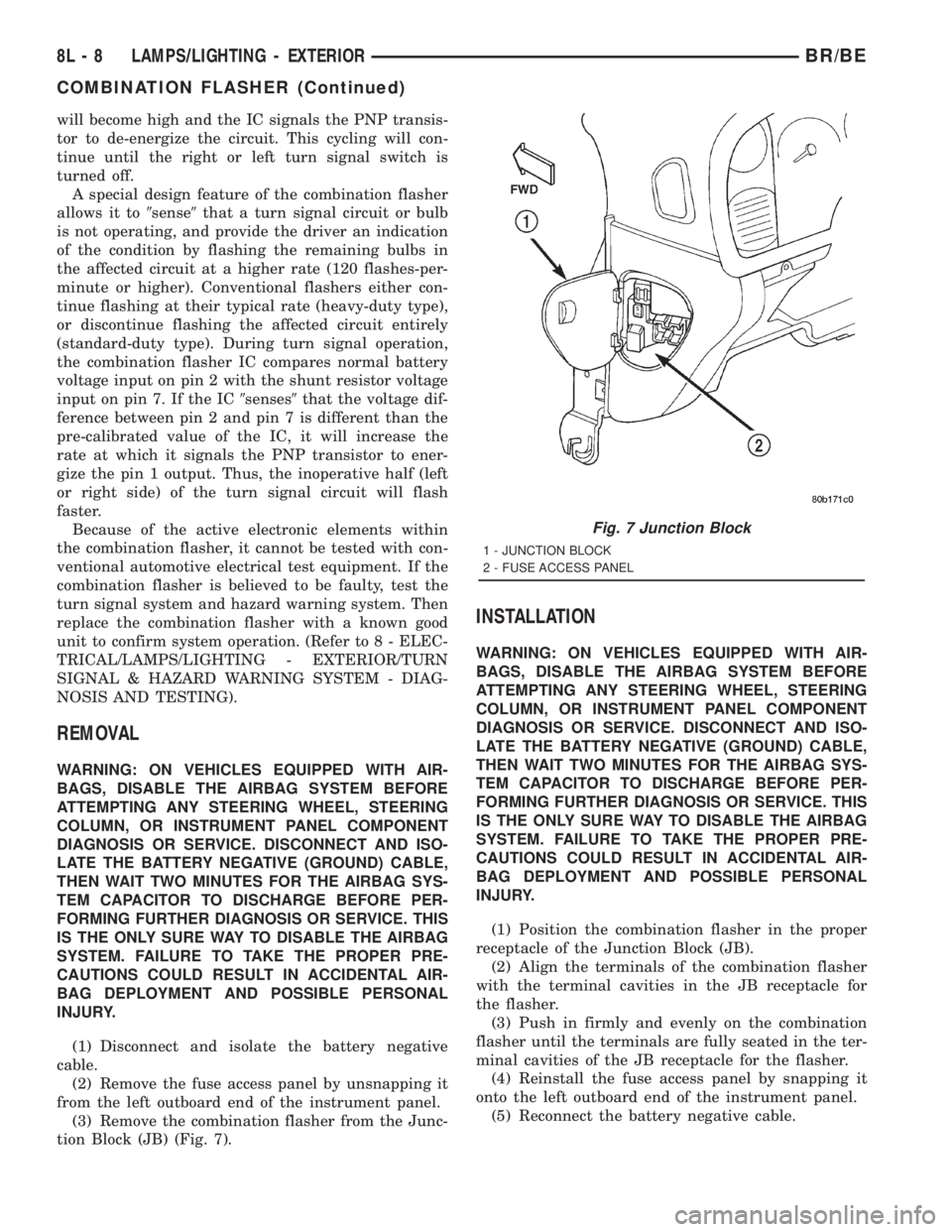
tion Block (JB) (Fig. 7).
INSTALLATION
WARNING: ON VEHICLES EQUIPPED WITH AIR-
BAGS, DISABLE THE AIRBAG SYSTEM BEFORE
ATTEMPTING ANY STEERING WHEEL, STEERING
COLUMN, OR INSTRUMENT PANEL COMPONENT
DIAGNOSIS OR SERVICE. DISCONNECT AND ISO-
LATE THE BATTERY NEGATIVE (GROUND) CABLE,
THEN WAIT TWO MINUTES FOR THE AIRBAG SYS-
TEM CAPACITOR TO DISCHARGE BEFORE PER-
FORMING FURTHER DIAGNOSIS OR SERVICE. THIS
IS THE ONLY SURE WAY TO DISABLE THE AIRBAG
SYSTEM. FAILURE TO TAKE THE PROPER PRE-
CAUTIONS COULD RESULT IN ACCIDENTAL AIR-
BAG DEPLOYMENT AND POSSIBLE PERSONAL
INJURY.
(1) Position the combination flasher in the proper
receptacle of the Junction Block (JB).
(2) Align the terminals of the combination flasher
with the terminal cavities in the JB receptacle for
the flasher.
(3) Push in firmly and evenly on the combination
flasher until the terminals are fully seated in the ter-
minal cavities of the JB receptacle for the flasher.
(4) Reinstall the fuse access panel by snapping it
onto the left outboard end of the instrument panel.
(5) Reconnect the battery negative cable.
Fig. 7 Junction Block
1 - JUNCTION BLOCK
2 - FUSE ACCESS PANEL
8L - 8 LAMPS/LIGHTING - EXTERIORBR/BE
COMBINATION FLASHER (Continued)
Page 610 of 2889
HEADLAMP
DESCRIPTION
Headlamps on the Ram Pick-Up are modular in
design. The turn/park lamp module is incorporated
into the headlamp module. The module contains two
bulbs; a dual filament headlamp bulb, and a dual fil-
ament turn/park bulb. The Sport headlamp module
has two separate bulbs for the headlamp illumina-
tion.
OPERATION
Headlamps and parking lamps are controlled by
the headlamp switch. The multifunction switch
mounted on the steering column controls the high
beam function, and the turn signal function.
DIAGNOSIS AND TESTING - HEADLAMP
A good ground is necessary for proper lighting
operation. Grounding is provided by the lamp socket
when it comes in contact with the metal body, or
through a separate ground wire.
Always begin any diagnosis by testing all of the
fuses and circuit breakers in the system. For com-
plete circuit diagrams, refer to the appropriate wir-
ing information. The wiring information includes
wiring diagrams, proper wire and connector repair
procedures, details of wire harness routing and
retention, connector pin-out information and location
views for the various wire harness connectors, splices
and grounds.
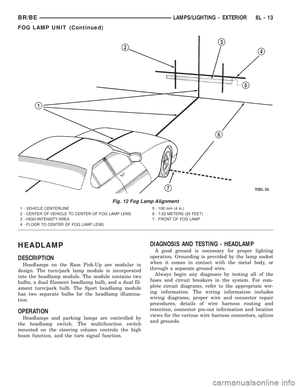
Fig. 12 Fog Lamp Alignment
1 - VEHICLE CENTERLINE
2 - CENTER OF VEHICLE TO CENTER OF FOG LAMP LENS
3 - HIGH-INTENSITY AREA
4 - FLOOR TO CENTER OF FOG LAMP LENS5 - 100 mm (4 in.)
6 - 7.62 METERS (25 FEET)
7 - FRONT OF FOG LAMP
BR/BELAMPS/LIGHTING - EXTERIOR 8L - 13
FOG LAMP UNIT (Continued)
Page 615 of 2889
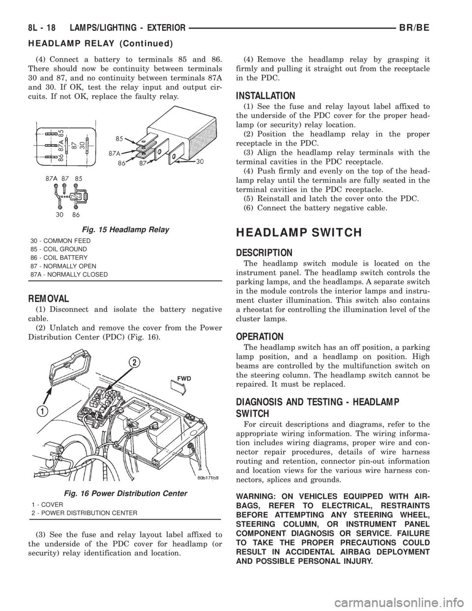
(4) Connect a battery to terminals 85 and 86.
There should now be continuity between terminals
30 and 87, and no continuity between terminals 87A
and 30. If OK, test the relay input and output cir-
cuits. If not OK, replace the faulty relay.
REMOVAL
(1) Disconnect and isolate the battery negative
cable.
(2) Unlatch and remove the cover from the Power
Distribution Center (PDC) (Fig. 16).
(3) See the fuse and relay layout label affixed to
the underside of the PDC cover for headlamp (or
security) relay identification and location.(4) Remove the headlamp relay by grasping it
firmly and pulling it straight out from the receptacle
in the PDC.
INSTALLATION
(1) See the fuse and relay layout label affixed to
the underside of the PDC cover for the proper head-
lamp (or security) relay location.
(2) Position the headlamp relay in the proper
receptacle in the PDC.
(3) Align the headlamp relay terminals with the
terminal cavities in the PDC receptacle.
(4) Push firmly and evenly on the top of the head-
lamp relay until the terminals are fully seated in the
terminal cavities in the PDC receptacle.
(5) Reinstall and latch the cover onto the PDC.
(6) Connect the battery negative cable.
HEADLAMP SWITCH
DESCRIPTION
The headlamp switch module is located on the
instrument panel. The headlamp switch controls the
parking lamps, and the headlamps. A separate switch
in the module controls the interior lamps and instru-
ment cluster illumination. This switch also contains
a rheostat for controlling the illumination level of the
cluster lamps.
OPERATION
The headlamp switch has an off position, a parking
lamp position, and a headlamp on position. High
beams are controlled by the multifunction switch on
the steering column. The headlamp switch cannot be
repaired. It must be replaced.
DIAGNOSIS AND TESTING - HEADLAMP
SWITCH
For circuit descriptions and diagrams, refer to the
appropriate wiring information. The wiring informa-
tion includes wiring diagrams, proper wire and con-
nector repair procedures, details of wire harness
routing and retention, connector pin-out information
and location views for the various wire harness con-
nectors, splices and grounds.
WARNING: ON VEHICLES EQUIPPED WITH AIR-
BAGS, REFER TO ELECTRICAL, RESTRAINTS
BEFORE ATTEMPTING ANY STEERING WHEEL,
STEERING COLUMN, OR INSTRUMENT PANEL
COMPONENT DIAGNOSIS OR SERVICE. FAILURE
TO TAKE THE PROPER PRECAUTIONS COULD
RESULT IN ACCIDENTAL AIRBAG DEPLOYMENT
AND POSSIBLE PERSONAL INJURY.
Fig. 15 Headlamp Relay
30 - COMMON FEED
85 - COIL GROUND
86 - COIL BATTERY
87 - NORMALLY OPEN
87A - NORMALLY CLOSED
Fig. 16 Power Distribution Center
1 - COVER
2 - POWER DISTRIBUTION CENTER
8L - 18 LAMPS/LIGHTING - EXTERIORBR/BE
HEADLAMP RELAY (Continued)