2001 DODGE RAM service
[x] Cancel search: servicePage 464 of 2889

ENGINE CONTROL MODULE
DESCRIPTION - ECM
The ECM is bolted to the left side of the engine
behind the fuel filter (Fig. 14). It is a separate com-
ponent and can be serviced. The FPCM is internal to
the fuel injection pump (Fig. 15) and cannot be ser-
viced.
OPERATION - ECM
The main functions of the Engine Control Module
(ECM) and Fuel Injection Pump Control Module
(FPCM) are to electrically control the fuel system.
The Powertrain Control Module (PCM)does not
controlthe fuel system.
The ECM can adapt its programming to meet
changing operating conditions.If the ECM has
been replaced, flashed or re-calibrated, the
ECM must learn the Accelerator Pedal Position
Sensor (APPS) idle voltage. Failure to learn
this voltage may result in unnecessary diagnos-
tic trouble codes. Refer to ECM Removal/Instal-
lation for learning procedures.
The ECM receives input signals from various
switches and sensors. Based on these inputs, the
ECM regulates various engine and vehicle operations
through different system components. These compo-
nents are referred to asECM Outputs.The sensors
and switches that provide inputs to the ECM are
consideredECM Inputs.NOTE: ECM Inputs:
²Accelerator Pedal Position Sensor (APPS) Volts
²APPS Idle Validation Switches #1 and #2
²Battery voltage
²Camshaft Position Sensor (CMP)
²CCD bus (+) circuits
²CCD bus (-) circuits
²Crankshaft Position Sensor (CKP)
²Data link connection for DRB scan tool
²(FPCM) Fuel Injection Pump Control Module
²Engine Coolant Temperature (ECT) sensor
²Ground circuits
²Intake manifold Air Temperature (IAT) sensor
²Manifold Air Pressure Sensor (Boost Pressure
Sensor)
²Oil pressure sensor
²PCM
²Power Take Off (PTO)
²Power ground
²Sensor return
²Signal ground
²Water-In-Fuel (WIF) sensor
Fig. 14 Engine Control Module (ECM) Location
1 - ENGINE CONTROL MODULE (ECM)
2 - HEX HEADED BOLT
3 - 50-WAY CONNECTOR
4 - FUEL TRANSFER PUMP
5 - MOUNTING BOLTS (3)
Fig. 15 Fuel Injection Pump Control Module (FPCM)
Location
1 - FPCM ELECTRICAL CONNECTOR
2 - HIGH-PRESSURE FUEL LINES
3 - FITTINGS
4 - FUEL INJECTION PUMP
5 - FPCM
BR/BEELECTRONIC CONTROL MODULES 8E - 13
Page 469 of 2889

Based on inputs that it receives, the PCM adjusts
ignition coil dwell. The PCM also adjusts the gener-
ator charge rate through control of the generator
field and provides speed control operation.
NOTE: PCM Inputs:
²A/C request (if equipped with factory A/C)
²A/C select (if equipped with factory A/C)
²Auto shutdown (ASD) sense
²Battery temperature
²Battery voltage
²Brake switch
²CCD bus (+) circuits
²CCD bus (-) circuits
²Camshaft position sensor signal
²Crankshaft position sensor
²Data link connection for DRB scan tool
²Engine coolant temperature sensor
²Fuel level
²Generator (battery voltage) output
²Ignition circuit sense (ignition switch in on/off/
crank/run position)
²Intake manifold air temperature sensor
²Leak detection pump (switch) sense (if equipped)
²Manifold absolute pressure (MAP) sensor
²Oil pressure
²Output shaft speed sensor
²Overdrive/override switch
²Oxygen sensors
²Park/neutral switch (auto. trans. only)
²Power ground
²Sensor return
²Signal ground
²Speed control multiplexed single wire input
²Throttle position sensor
²Transmission governor pressure sensor
²Transmission temperature sensor
²Vehicle speed inputs from ABS or RWAL system
NOTE: PCM Outputs:
²A/C clutch relay
²Auto shutdown (ASD) relay
²CCD bus (+/-) circuits for: speedometer, voltme-
ter, fuel gauge, oil pressure gauge/lamp, engine temp.
gauge and speed control warn. lamp
²Data link connection for DRB scan tool
²EGR valve control solenoid (if equipped)
²EVAP canister purge solenoid
²Five volt sensor supply (primary)
²Five volt sensor supply (secondary)
²Fuel injectors
²Fuel pump relay
²Generator field driver (-)
²Generator field driver (+)
²Generator lamp (if equipped)²Idle air control (IAC) motor
²Ignition coil
²Leak detection pump (if equipped)
²Malfunction indicator lamp (Check engine lamp).
Driven through CCD circuits.
²Overdrive indicator lamp (if equipped)
²Service Reminder Indicator (SRI) Lamp (MAINT
REQ'D lamp). Driven through CCD circuits.
²Speed control vacuum solenoid
²Speed control vent solenoid
²Tachometer (if equipped). Driven through CCD
circuits.
²Transmission convertor clutch circuit
²Transmission 3±4 shift solenoid
²Transmission relay
²Transmission temperature lamp (if equipped)
²Transmission variable force solenoid
OPERATION - DIESEL
Two different control modules are used: The Pow-
ertrain Control Module (PCM), and the Engine Con-
trol Module (ECM). The ECMcontrolsthe fuel
system. The PCMdoes not controlthe fuel system.
The PCM's main function is to control: the vehicle
charging system, speed control system, transmission,
air conditioning system and certain bussed messages.
The PCM can adapt its programming to meet
changing operating conditions.
The PCM receives input signals from various
switches and sensors. Based on these inputs, the
PCM regulates various engine and vehicle operations
through different system components. These compo-
nents are referred to asPCM Outputs.The sensors
and switches that provide inputs to the PCM are con-
sideredPCM Inputs.
NOTE: PCM Inputs:
²A/C request (if equipped with factory A/C)
²A/C select (if equipped with factory A/C)
²Accelerator Pedal Position Sensor (APPS) output
from ECM
²Auto shutdown (ASD) relay sense
²Battery temperature sensor
²Battery voltage
²Brake switch
²CCD bus (+) circuits
²CCD bus (-) circuits
²Crankshaft Position Sensor (CKP) output from
ECM
²Data link connection for DRB scan tool
²Fuel level sensor
²Generator (battery voltage) output
²Ignition sense
²Output shaft speed sensor
²Overdrive/override switch
²Park/neutral switch (auto. trans. only)
8E - 18 ELECTRONIC CONTROL MODULESBR/BE
POWERTRAIN CONTROL MODULE (Continued)
Page 472 of 2889
ENGINE SYSTEMS
TABLE OF CONTENTS
page page
BATTERY SYSTEM......................... 1
CHARGING.............................. 27STARTING............................... 32
BATTERY SYSTEM
TABLE OF CONTENTS
page page
BATTERY SYSTEM
DESCRIPTION............................1
OPERATION.............................2
DIAGNOSIS AND TESTING..................2
BATTERY SYSTEM......................2
CLEANING...............................5
INSPECTION.............................5
SPECIFICATIONS.........................6
BATTERY
DESCRIPTION............................6
OPERATION.............................7
DIAGNOSIS AND TESTING..................7
BATTERY..............................7
STANDARD PROCEDURE...................8
CHECKING BATTERY ELECTROLYTE
LEVEL................................8
BATTERY CHARGING....................9
BUILT-IN INDICATOR TEST...............11
HYDROMETER TEST....................12
OPEN-CIRCUIT VOLTAGE TEST...........13
LOAD TEST...........................14IGNITION-OFF DRAW TEST...............15
REMOVAL..............................17
INSTALLATION...........................17
BATTERY HOLDDOWN
DESCRIPTION...........................18
OPERATION.............................18
REMOVAL..............................18
INSTALLATION...........................18
BATTERY CABLE
DESCRIPTION...........................19
OPERATION.............................20
DIAGNOSIS AND TESTING.................20
BATTERY CABLES......................20
REMOVAL..............................23
INSTALLATION...........................23
BATTERY TRAY
DESCRIPTION...........................24
OPERATION.............................25
REMOVAL..............................25
INSTALLATION...........................25
BATTERY SYSTEM
DESCRIPTION
A single 12-volt battery system is standard factory-
installed equipment on gasoline engine equipped
models. Models equipped with a diesel engine utilize
two 12-volt batteries connected in parallel. All of the
components of the battery system are located within
the engine compartment of the vehicle. The service
information for the battery system in this vehicle
covers the following related components, which are
covered in further detail elsewhere in this service
manual:²Battery- The storage battery provides a reli-
able means of storing a renewable source of electrical
energy within the vehicle.
²Battery Cable- The battery cables connect the
battery terminal posts to the vehicle electrical sys-
tem.
²Battery Holddown- The battery holddown
hardware secures the battery in the battery tray in
the engine compartment.
²Battery Tray- The battery tray provides a
secure mounting location in the vehicle for the bat-
tery and an anchor point for the battery holddown
hardware.
BR/BEENGINE SYSTEMS 8F - 1
Page 473 of 2889

For battery system maintenance schedules and
jump starting procedures, see the owner's manual in
the vehicle glove box. Optionally, refer to Lubrication
and Maintenance for the recommended battery main-
tenance schedules and for the proper battery jump
starting procedures. While battery charging can be
considered a maintenance procedure, the battery
charging procedures and related information are
located in the standard procedures section of this ser-
vice manual. This was done because the battery must
be fully-charged before any battery system diagnosis
or testing procedures can be performed. Refer to
Standard procedures for the proper battery charging
procedures.
OPERATION
The battery system is designed to provide a safe,
efficient, reliable and mobile means of producing,
delivering and storing electrical energy. This electri-
cal energy is required to operate the engine starting
system, as well as to operate many of the other vehi-
cle accessory systems for limited durations while the
engine and/or the charging system are not operating.
The battery system is also designed to provide a
reserve of electrical energy to supplement the charg-
ing system for short durations while the engine is
running and the electrical current demands of the
vehicle exceed the output of the charging system. In
addition to producing, delivering, and storing electri-
cal energy for the vehicle, the battery system serves
as a capacitor and voltage stabilizer for the vehicle
electrical system. It absorbs most abnormal or tran-
sient voltages caused by the switching of any of the
electrical components or circuits in the vehicle.
DIAGNOSIS AND TESTING - BATTERY SYSTEM
The battery, starting, and charging systems in the
vehicle operate with one another and must be tested
as a single complete system. In order for the engine
to start and the battery to charge properly, all of the
components that are used in these systems must per-
form within specifications. It is important that the
battery, starting, and charging systems be thoroughly
tested and inspected any time a battery needs to be
charged or replaced. The cause of abnormal battery
discharge, overcharging or early battery failure must
be diagnosed and corrected before a battery is
replaced and before a vehicle is returned to service.
The service information for these systems has been
separated within this service manual to make it eas-
ier to locate the specific information you are seeking.
However, when attempting to diagnose any of these
systems, it is important that you keep their interde-
pendency in mind.
The diagnostic procedures used for the battery,
starting, and charging systems include the most
basic conventional diagnostic methods, to the more
sophisticated On-Board Diagnostics (OBD) built into
the Powertrain Control Module (PCM). Use of an
induction-type milliampere ammeter, a volt/ohmme-
ter, a battery charger, a carbon pile rheostat (load
tester) and a 12-volt test lamp may be required. All
OBD-sensed systems are monitored by the PCM.
Each monitored circuit is assigned a Diagnostic Trou-
ble Code (DTC). The PCM will store a DTC in elec-
tronic memory for any failure it detects. Refer to
Charging System for the proper charging system on-
board diagnostic test procedures.
8F - 2 BATTERY SYSTEMBR/BE
BATTERY SYSTEM (Continued)
Page 476 of 2889
²A faulty or incorrect starting system component.
Refer to Starting System for the proper starting sys-
tem diagnosis and testing procedures.
²A faulty or incorrect battery. Refer to Standard
Procedures for the proper battery diagnosis and test-
ing procedures. Refer to Battery System Specifica-
tions for the proper specifications.
CLEANING
The following information details the recommended
cleaning procedures for the battery and related com-
ponents. In addition to the maintenance schedules
found in this service manual and the owner's man-
ual, it is recommended that these procedures be per-
formed any time the battery or related components
must be removed for vehicle service.
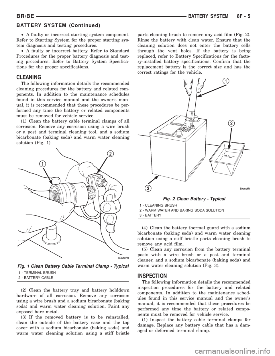
(1) Clean the battery cable terminal clamps of all
corrosion. Remove any corrosion using a wire brush
or a post and terminal cleaning tool, and a sodium
bicarbonate (baking soda) and warm water cleaning
solution (Fig. 1).
(2) Clean the battery tray and battery holddown
hardware of all corrosion. Remove any corrosion
using a wire brush and a sodium bicarbonate (baking
soda) and warm water cleaning solution. Paint any
exposed bare metal.
(3) If the removed battery is to be reinstalled,
clean the outside of the battery case and the top
cover with a sodium bicarbonate (baking soda) and
warm water cleaning solution using a stiff bristleparts cleaning brush to remove any acid film (Fig. 2).
Rinse the battery with clean water. Ensure that the
cleaning solution does not enter the battery cells
through the vent holes. If the battery is being
replaced, refer to Battery Specifications for the facto-
ry-installed battery specifications. Confirm that the
replacement battery is the correct size and has the
correct ratings for the vehicle.
(4) Clean the battery thermal guard with a sodium
bicarbonate (baking soda) and warm water cleaning
solution using a stiff bristle parts cleaning brush to
remove any acid film.
(5) Clean any corrosion from the battery terminal
posts with a wire brush or a post and terminal
cleaner, and a sodium bicarbonate (baking soda) and
warm water cleaning solution (Fig. 3).
INSPECTION
The following information details the recommended
inspection procedures for the battery and related
components. In addition to the maintenance sched-
ules found in this service manual and the owner's
manual, it is recommended that these procedures be
performed any time the battery or related compo-
nents must be removed for vehicle service.
(1) Inspect the battery cable terminal clamps for
damage. Replace any battery cable that has a dam-
aged or deformed terminal clamp.
Fig. 1 Clean Battery Cable Terminal Clamp - Typical
1 - TERMINAL BRUSH
2 - BATTERY CABLE
Fig. 2 Clean Battery - Typical
1 - CLEANING BRUSH
2 - WARM WATER AND BAKING SODA SOLUTION
3 - BATTERY
BR/BEBATTERY SYSTEM 8F - 5
BATTERY SYSTEM (Continued)
Page 478 of 2889
lead dioxide (positive plate) or sponge lead (negative
plate). Insulators or plate separators made of a non-
conductive material are inserted between the positive
and negative plates to prevent them from contacting
or shorting against one another. These dissimilar
metal plates are submerged in a sulfuric acid and
water solution called an electrolyte.
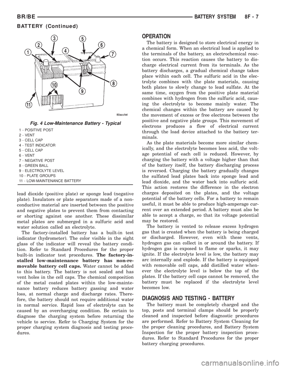
The factory-installed battery has a built-in test
indicator (hydrometer). The color visible in the sight
glass of the indicator will reveal the battery condi-
tion. Refer to Standard Procedures for the proper
built-in indicator test procedures.The factory-in-
stalled low-maintenance battery has non-re-
movable battery cell caps.Water cannot be added
to this battery. The battery is not sealed and has
vent holes in the cell caps. The chemical composition
of the metal coated plates within the low-mainte-
nance battery reduces battery gassing and water
loss, at normal charge and discharge rates. There-
fore, the battery should not require additional water
in normal service. Rapid loss of electrolyte can be
caused by an overcharging condition. Be certain to
diagnose the charging system before returning the
vehicle to service. Refer to Charging System for the
proper charging system diagnosis and testing proce-
dures.
OPERATION
The battery is designed to store electrical energy in
a chemical form. When an electrical load is applied to
the terminals of the battery, an electrochemical reac-
tion occurs. This reaction causes the battery to dis-
charge electrical current from its terminals. As the
battery discharges, a gradual chemical change takes
place within each cell. The sulfuric acid in the elec-
trolyte combines with the plate materials, causing
both plates to slowly change to lead sulfate. At the
same time, oxygen from the positive plate material
combines with hydrogen from the sulfuric acid, caus-
ing the electrolyte to become mainly water. The
chemical changes within the battery are caused by
the movement of excess or free electrons between the
positive and negative plate groups. This movement of
electrons produces a flow of electrical current
through the load device attached to the battery ter-
minals.
As the plate materials become more similar chem-
ically, and the electrolyte becomes less acid, the volt-
age potential of each cell is reduced. However, by
charging the battery with a voltage higher than that
of the battery itself, the battery discharging process
is reversed. Charging the battery gradually changes
the sulfated lead plates back into sponge lead and
lead dioxide, and the water back into sulfuric acid.
This action restores the difference in the electron
charges deposited on the plates, and the voltage
potential of the battery cells. For a battery to remain
useful, it must be able to produce high-amperage cur-
rent over an extended period. A battery must also be
able to accept a charge, so that its voltage potential
may be restored.
The battery is vented to release excess hydrogen
gas that is created when the battery is being charged
or discharged. However, even with these vents,
hydrogen gas can collect in or around the battery. If
hydrogen gas is exposed to flame or sparks, it may
ignite. If the electrolyte level is low, the battery may
arc internally and explode. If the battery is equipped
with removable cell caps, add distilled water when-
ever the electrolyte level is below the top of the
plates. If the battery cell caps cannot be removed, the
battery must be replaced if the electrolyte level
becomes low.
DIAGNOSIS AND TESTING - BATTERY
The battery must be completely charged and the
top, posts and terminal clamps should be properly
cleaned and inspected before diagnostic procedures
are performed. Refer to Battery System Cleaning for
the proper cleaning procedures, and Battery System
Inspection for the proper battery inspection proce-
dures. Refer to Standard Procedures for the proper
battery charging procedures.
Fig. 4 Low-Maintenance Battery - Typical
1 - POSITIVE POST
2 - VENT
3 - CELL CAP
4 - TEST INDICATOR
5 - CELL CAP
6 - VENT
7 - NEGATIVE POST
8 - GREEN BALL
9 - ELECTROLYTE LEVEL
10 - PLATE GROUPS
11 - LOW-MAINTENANCE BATTERY
BR/BEBATTERY SYSTEM 8F - 7
BATTERY (Continued)
Page 481 of 2889
NOTE: Models equipped with the diesel engine
option are equipped with two 12-volt batteries, con-
nected in parallel (positive-to-positive and negative-
to-negative). In order to ensure proper charging of
each battery, these batteries MUST be disconnected
from each other, as well as from the vehicle electri-
cal system, while being charged.
Some battery chargers are equipped with polarity-
sensing circuitry. This circuitry protects the battery
charger and the battery from being damaged if they
are improperly connected. If the battery state-of-
charge is too low for the polarity-sensing circuitry to
detect, the battery charger will not operate. This
makes it appear that the battery will not accept
charging current. See the instructions provided by
the manufacturer of the battery charger for details
on how to bypass the polarity-sensing circuitry.
After the battery has been charged to 12.4 volts or
greater, perform a load test to determine the battery
cranking capacity. Refer to Standard Procedures for
the proper battery load test procedures. If the battery
will endure a load test, return the battery to service.
If the battery will not endure a load test, it is faulty
and must be replaced.
Clean and inspect the battery hold downs, tray,
terminals, posts, and top before completing battery
service. Refer to Battery System Cleaning for the
proper battery system cleaning procedures, and Bat-
tery System Inspection for the proper battery system
inspection procedures.
CHARGING A COMPLETELY DISCHARGED
BATTERY
The following procedure should be used to recharge
a completely discharged battery. Unless this proce-
dure is properly followed, a good battery may be
needlessly replaced.
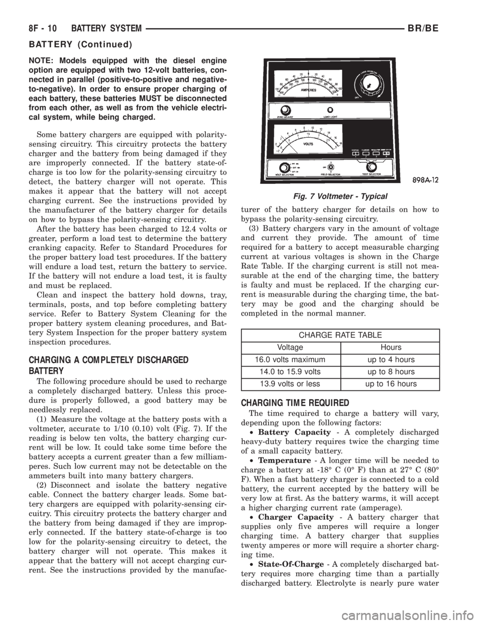
(1) Measure the voltage at the battery posts with a
voltmeter, accurate to 1/10 (0.10) volt (Fig. 7). If the
reading is below ten volts, the battery charging cur-
rent will be low. It could take some time before the
battery accepts a current greater than a few milliam-
peres. Such low current may not be detectable on the
ammeters built into many battery chargers.
(2) Disconnect and isolate the battery negative
cable. Connect the battery charger leads. Some bat-
tery chargers are equipped with polarity-sensing cir-
cuitry. This circuitry protects the battery charger and
the battery from being damaged if they are improp-
erly connected. If the battery state-of-charge is too
low for the polarity-sensing circuitry to detect, the
battery charger will not operate. This makes it
appear that the battery will not accept charging cur-
rent. See the instructions provided by the manufac-turer of the battery charger for details on how to
bypass the polarity-sensing circuitry.
(3) Battery chargers vary in the amount of voltage
and current they provide. The amount of time
required for a battery to accept measurable charging
current at various voltages is shown in the Charge
Rate Table. If the charging current is still not mea-
surable at the end of the charging time, the battery
is faulty and must be replaced. If the charging cur-
rent is measurable during the charging time, the bat-
tery may be good and the charging should be
completed in the normal manner.
CHARGE RATE TABLE
Voltage Hours
16.0 volts maximum up to 4 hours
14.0 to 15.9 volts up to 8 hours
13.9 volts or less up to 16 hours
CHARGING TIME REQUIRED
The time required to charge a battery will vary,
depending upon the following factors:
²Battery Capacity- A completely discharged
heavy-duty battery requires twice the charging time
of a small capacity battery.
²Temperature- A longer time will be needed to
charge a battery at -18É C (0É F) than at 27É C (80É
F). When a fast battery charger is connected to a cold
battery, the current accepted by the battery will be
very low at first. As the battery warms, it will accept
a higher charging current rate (amperage).
²Charger Capacity- A battery charger that
supplies only five amperes will require a longer
charging time. A battery charger that supplies
twenty amperes or more will require a shorter charg-
ing time.
²State-Of-Charge- A completely discharged bat-
tery requires more charging time than a partially
discharged battery. Electrolyte is nearly pure water
Fig. 7 Voltmeter - Typical
8F - 10 BATTERY SYSTEMBR/BE
BATTERY (Continued)
Page 482 of 2889
in a completely discharged battery. At first, the
charging current (amperage) will be low. As the bat-
tery charges, the specific gravity of the electrolyte
will gradually rise.
The Battery Charging Time Table gives an indica-
tion of the time required to charge a typical battery
at room temperature based upon the battery state-of-
charge and the charger capacity.
BATTERY CHARGING TIME TABLE
Charging
Amperage5 Amps10
Amps20 Amps
Open Circuit
VoltageHours Charging @ 21É C
(70É F)
12.25 to 12.49 6 hours 3 hours 1.5
hours
12.00 to 12.24 10 hours 5 hours 2.5
hours
10.00 to 11.99 14 hours 7 hours 3.5
hours
Below 10.00 18 hours 9 hours 4.5
hours
STANDARD PROCEDURE - BUILT-IN
INDICATOR TEST
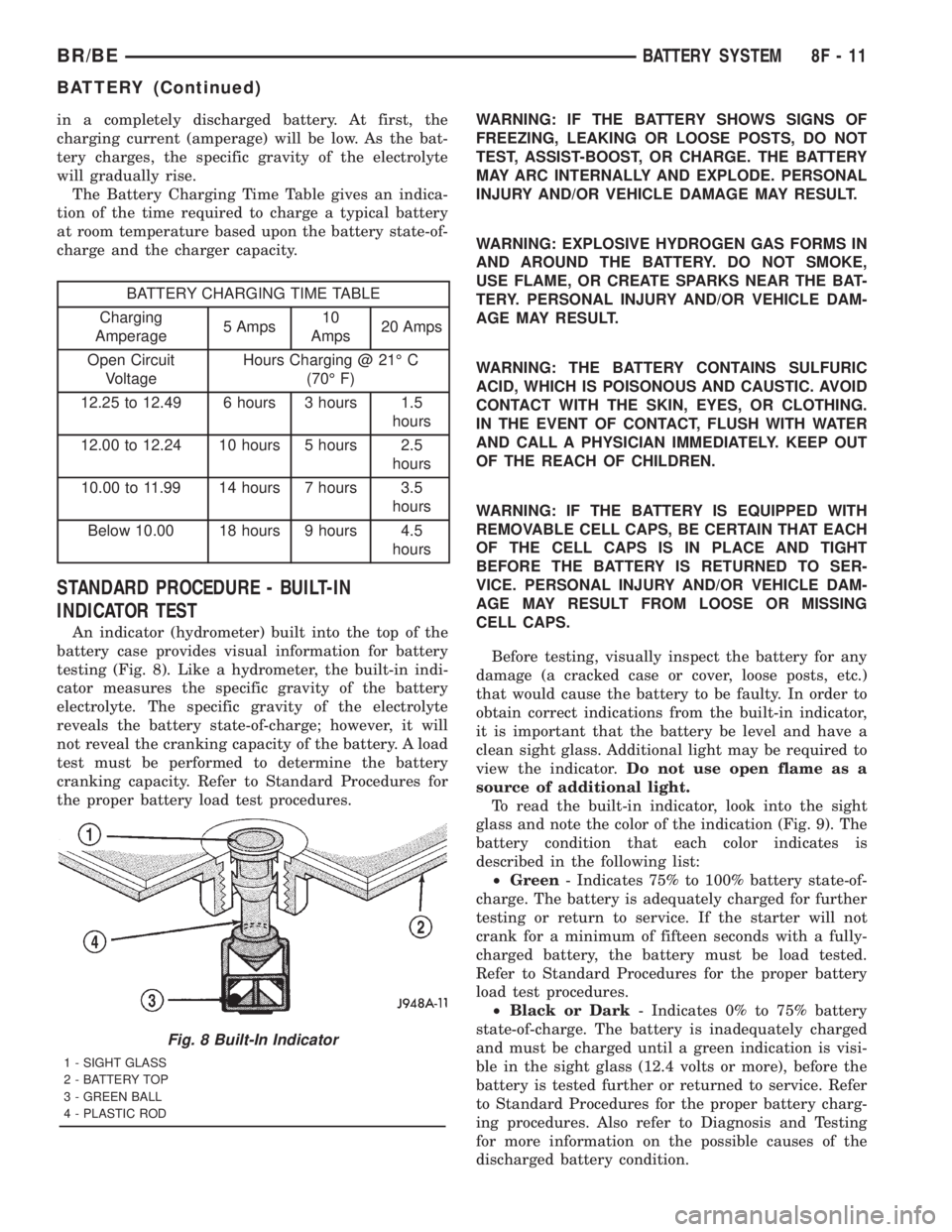
An indicator (hydrometer) built into the top of the
battery case provides visual information for battery
testing (Fig. 8). Like a hydrometer, the built-in indi-
cator measures the specific gravity of the battery
electrolyte. The specific gravity of the electrolyte
reveals the battery state-of-charge; however, it will
not reveal the cranking capacity of the battery. A load
test must be performed to determine the battery
cranking capacity. Refer to Standard Procedures for
the proper battery load test procedures.WARNING: IF THE BATTERY SHOWS SIGNS OF
FREEZING, LEAKING OR LOOSE POSTS, DO NOT
TEST, ASSIST-BOOST, OR CHARGE. THE BATTERY
MAY ARC INTERNALLY AND EXPLODE. PERSONAL
INJURY AND/OR VEHICLE DAMAGE MAY RESULT.
WARNING: EXPLOSIVE HYDROGEN GAS FORMS IN
AND AROUND THE BATTERY. DO NOT SMOKE,
USE FLAME, OR CREATE SPARKS NEAR THE BAT-
TERY. PERSONAL INJURY AND/OR VEHICLE DAM-
AGE MAY RESULT.
WARNING: THE BATTERY CONTAINS SULFURIC
ACID, WHICH IS POISONOUS AND CAUSTIC. AVOID
CONTACT WITH THE SKIN, EYES, OR CLOTHING.
IN THE EVENT OF CONTACT, FLUSH WITH WATER
AND CALL A PHYSICIAN IMMEDIATELY. KEEP OUT
OF THE REACH OF CHILDREN.
WARNING: IF THE BATTERY IS EQUIPPED WITH
REMOVABLE CELL CAPS, BE CERTAIN THAT EACH
OF THE CELL CAPS IS IN PLACE AND TIGHT
BEFORE THE BATTERY IS RETURNED TO SER-
VICE. PERSONAL INJURY AND/OR VEHICLE DAM-
AGE MAY RESULT FROM LOOSE OR MISSING
CELL CAPS.
Before testing, visually inspect the battery for any
damage (a cracked case or cover, loose posts, etc.)
that would cause the battery to be faulty. In order to
obtain correct indications from the built-in indicator,
it is important that the battery be level and have a
clean sight glass. Additional light may be required to
view the indicator.Do not use open flame as a
source of additional light.
To read the built-in indicator, look into the sight
glass and note the color of the indication (Fig. 9). The
battery condition that each color indicates is
described in the following list:
²Green- Indicates 75% to 100% battery state-of-
charge. The battery is adequately charged for further
testing or return to service. If the starter will not
crank for a minimum of fifteen seconds with a fully-
charged battery, the battery must be load tested.
Refer to Standard Procedures for the proper battery
load test procedures.
²Black or Dark- Indicates 0% to 75% battery
state-of-charge. The battery is inadequately charged
and must be charged until a green indication is visi-
ble in the sight glass (12.4 volts or more), before the
battery is tested further or returned to service. Refer
to Standard Procedures for the proper battery charg-
ing procedures. Also refer to Diagnosis and Testing
for more information on the possible causes of the
discharged battery condition.
Fig. 8 Built-In Indicator
1 - SIGHT GLASS
2 - BATTERY TOP
3 - GREEN BALL
4 - PLASTIC ROD
BR/BEBATTERY SYSTEM 8F - 11
BATTERY (Continued)