2001 DODGE RAM service
[x] Cancel search: servicePage 497 of 2889

(8) Install and tighten the two screws with wash-
ers that secure the outboard side of the battery tray
to the inner fender shield. Tighten the screws to 15.8
N´m (140 in. lbs.).
(9) Final tighten the four nuts with washers that
secure the battery tray support to the stud plates on
the front wheelhouse inner panel. Tighten the nuts
to 15.8 N´m (140 in. lbs.).(10) If the left battery tray is being installed,
install the battery temperature sensor onto the left
battery tray. Refer toBattery Temperature Sensor
in the index of this service manual for the location of
the proper battery temperature sensor installation
procedures.
(11) Install the battery onto the battery tray. Refer
toBatteryin this group for the location of the
proper battery installation procedures.
8F - 26 BATTERY SYSTEMBR/BE
BATTERY TRAY (Continued)
Page 499 of 2889
INSPECTION
The Powertrain Control Module (PCM) monitors
critical input and output circuits of the charging sys-
tem, making sure they are operational. A Diagnostic
Trouble Code (DTC) is assigned to each input and
output circuit monitored by the On-Board Diagnostic
(OBD) system. Some charging system circuits are
checked continuously, and some are checked only
under certain conditions.
Refer to Diagnostic Trouble Codes in; Powertrain
Control Module; Electronic Control Modules for more
DTC information. This will include a complete list of
DTC's including DTC's for the charging system.
To perform a complete test of the charging system,
refer to the appropriate Powertrain Diagnostic Proce-
dures service manual and the DRBtscan tool. Per-
form the following inspections before attaching the
scan tool.
(1) Inspect the battery condition. Refer to 8, Bat-
tery for procedures.(2) Inspect condition of battery cable terminals,
battery posts, connections at engine block, starter
solenoid and relay. They should be clean and tight.
Repair as required.
(3) Inspect all fuses in both the fuseblock and
Power Distribution Center (PDC) for tightness in
receptacles. They should be properly installed and
tight. Repair or replace as required.
(4) Inspect generator mounting bolts for tightness.
Replace or tighten bolts if required. Refer to the Gen-
erator Removal/Installation section of this group for
torque specifications.
(5) Inspect generator drive belt condition and ten-
sion. Tighten or replace belt as required. Refer to
Belt Tension Specifications in 7, Cooling System.
(6) Inspect automatic belt tensioner (if equipped).
Refer to 7, Cooling System for information.
(7) Inspect generator electrical connections at gen-
erator field, battery output, and ground terminal (if
equipped). Also check generator ground wire connec-
tion at engine (if equipped). They should all be clean
and tight. Repair as required.
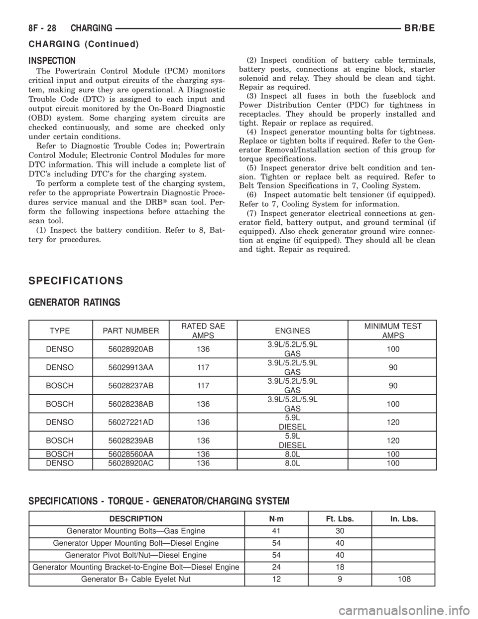
SPECIFICATIONS
GENERATOR RATINGS
TYPE PART NUMBERRATED SAE
AMPSENGINESMINIMUM TEST
AMPS
DENSO 56028920AB 1363.9L/5.2L/5.9L
GAS100
DENSO 56029913AA 1173.9L/5.2L/5.9L
GAS90
BOSCH 56028237AB 1173.9L/5.2L/5.9L
GAS90
BOSCH 56028238AB 1363.9L/5.2L/5.9L
GAS100
DENSO 56027221AD 1365.9L
DIESEL120
BOSCH 56028239AB 1365.9L
DIESEL120
BOSCH 56028560AA 136 8.0L 100
DENSO 56028920AC 136 8.0L 100
SPECIFICATIONS - TORQUE - GENERATOR/CHARGING SYSTEM
DESCRIPTION N´m Ft. Lbs. In. Lbs.
Generator Mounting BoltsÐGas Engine 41 30
Generator Upper Mounting BoltÐDiesel Engine 54 40
Generator Pivot Bolt/NutÐDiesel Engine 54 40
Generator Mounting Bracket-to-Engine BoltÐDiesel Engine 24 18
Generator B+ Cable Eyelet Nut 12 9 108
8F - 28 CHARGINGBR/BE
CHARGING (Continued)
Page 500 of 2889
BATTERY TEMPERATURE
SENSOR
DESCRIPTION
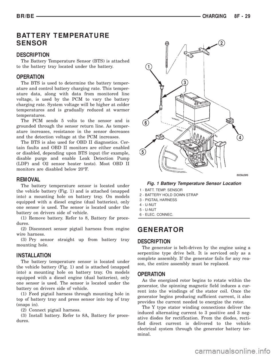
The Battery Temperature Sensor (BTS) is attached
to the battery tray located under the battery.
OPERATION
The BTS is used to determine the battery temper-
ature and control battery charging rate. This temper-
ature data, along with data from monitored line
voltage, is used by the PCM to vary the battery
charging rate. System voltage will be higher at colder
temperatures and is gradually reduced at warmer
temperatures.
The PCM sends 5 volts to the sensor and is
grounded through the sensor return line. As temper-
ature increases, resistance in the sensor decreases
and the detection voltage at the PCM increases.
The BTS is also used for OBD II diagnostics. Cer-
tain faults and OBD II monitors are either enabled
or disabled, depending upon BTS input (for example,
disable purge and enable Leak Detection Pump
(LDP) and O2 sensor heater tests). Most OBD II
monitors are disabled below 20ÉF.
REMOVAL
The battery temperature sensor is located under
the vehicle battery (Fig. 1) and is attached (snapped
into) a mounting hole on battery tray. On models
equipped with a diesel engine (dual batteries), only
one sensor is used. The sensor is located under the
battery on drivers side of vehicle.
(1) Remove battery. Refer to 8, Battery for proce-
dures.
(2) Disconnect sensor pigtail harness from engine
wire harness.
(3) Pry sensor straight up from battery tray
mounting hole.
INSTALLATION
The battery temperature sensor is located under
the vehicle battery (Fig. 1) and is attached (snapped
into) a mounting hole on battery tray. On models
equipped with a diesel engine (dual batteries), only
one sensor is used. The sensor is located under the
battery on drivers side of vehicle.
(1) Feed pigtail harness through mounting hole in
top of battery tray and press sensor into top of tray
(snaps in).
(2) Connect pigtail harness.
(3) Install battery. Refer to 8A, Battery for proce-
dures.
GENERATOR
DESCRIPTION
The generator is belt-driven by the engine using a
serpentine type drive belt. It is serviced only as a
complete assembly. If the generator fails for any rea-
son, the entire assembly must be replaced.
OPERATION
As the energized rotor begins to rotate within the
generator, the spinning magnetic field induces a cur-
rent into the windings of the stator coil. Once the
generator begins producing sufficient current, it also
provides the current needed to energize the rotor.
The Y type stator winding connections deliver the
induced alternating current to 3 positive and 3 neg-
ative diodes for rectification. From the diodes, recti-
fied direct current is delivered to the vehicle
electrical system through the generator battery ter-
minal.
Fig. 1 Battery Temperature Sensor Location
1 - BATT. TEMP. SENSOR
2 - BATTERY HOLD DOWN STRAP
3 - PIGTAIL HARNESS
4 - U-NUT
5 - U-NUT
6 - ELEC. CONNEC.
BR/BECHARGING 8F - 29
Page 502 of 2889
CAUTION: When installing a serpentine accessory
drive belt, the belt MUST be routed correctly. The
water pump will be rotating in the wrong direction if
the belt is installed incorrectly, causing the engine
to overheat. Refer to belt routing label in engine
compartment, or refer to Belt Schematics in Group
7, Cooling System.
(4) Install generator drive belt. Refer to 7, Cooling
System for procedure.(5) Install negative battery cable(s) to battery(s).
VOLTAGE REGULATOR
DESCRIPTION
The Electronic Voltage Regulator (EVR) is not a
separate component. It is actually a voltage regulat-
ing circuit located within the Powertrain Control
Module (PCM). The EVR is not serviced separately. If
replacement is necessary, the PCM must be replaced.
OPERATION
The amount of direct current produced by the gen-
erator is controlled by EVR circuitry contained
within the PCM. This circuitry is connected in series
with the generators second rotor field terminal and
its ground.
Voltage is regulated by cycling the ground path to
control the strength of the rotor magnetic field. The
EVR circuitry monitors system line voltage (B+) and
battery temperature (refer to Battery Temperature
Sensor for more information). It then determines a
target charging voltage. If sensed battery voltage is
0.5 volts or lower than the target voltage, the PCM
grounds the field winding until sensed battery volt-
age is 0.5 volts above target voltage. A circuit in the
PCM cycles the ground side of the generator field up
to 100 times per second (100Hz), but has the capabil-
ity to ground the field control wire 100% of the time
(full field) to achieve the target voltage. If the charg-
ing rate cannot be monitored (limp-in), a duty cycle
of 25% is used by the PCM in order to have some
generator output. Also refer to Charging System
Operation for additional information.
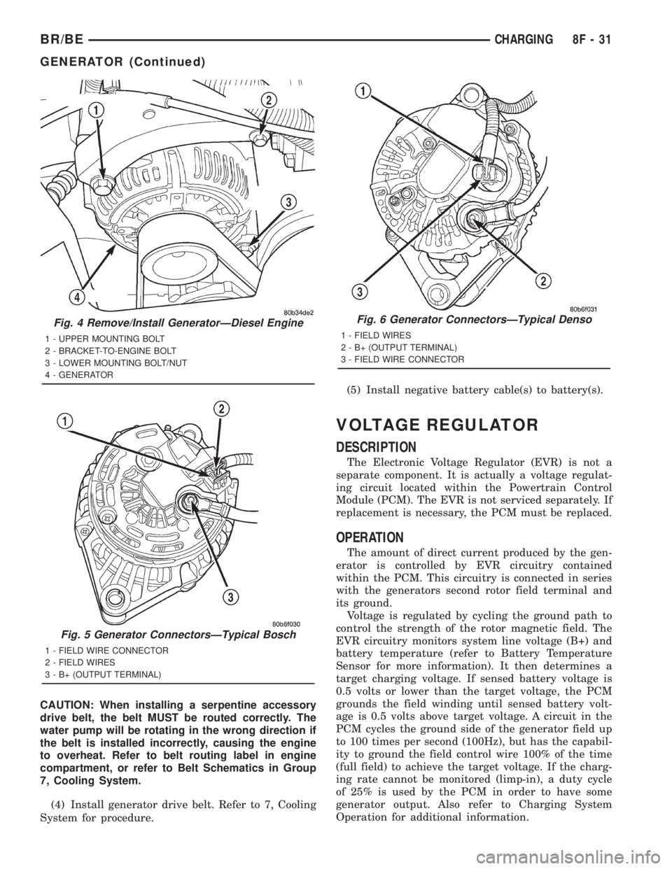
Fig. 4 Remove/Install GeneratorÐDiesel Engine
1 - UPPER MOUNTING BOLT
2 - BRACKET-TO-ENGINE BOLT
3 - LOWER MOUNTING BOLT/NUT
4 - GENERATOR
Fig. 5 Generator ConnectorsÐTypical Bosch
1 - FIELD WIRE CONNECTOR
2 - FIELD WIRES
3 - B+ (OUTPUT TERMINAL)
Fig. 6 Generator ConnectorsÐTypical Denso
1 - FIELD WIRES
2 - B+ (OUTPUT TERMINAL)
3 - FIELD WIRE CONNECTOR
BR/BECHARGING 8F - 31
GENERATOR (Continued)
Page 505 of 2889
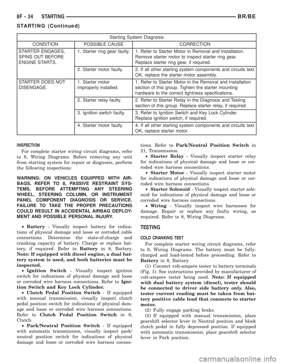
Starting System Diagnosis
CONDITION POSSIBLE CAUSE CORRECTION
STARTER ENGAGES,
SPINS OUT BEFORE
ENGINE STARTS.1. Starter ring gear faulty. 1. Refer to Starter Motor in Removal and Installation.
Remove starter motor to inspect starter ring gear.
Replace starter ring gear, if required.
2. Starter motor faulty. 2. If all other starting system components and circuits test
OK, replace the starter motor assembly.
STARTER DOES NOT
DISENGAGE.1. Starter motor
improperly installed.1. Refer to Starter Motor in the Removal and Installation
section of this group. Tighten the starter mounting
hardware to the correct tightness specifications.
2. Starter relay faulty. 2. Refer to Starter Relay in the Diagnosis and Testing
section of this group. Replace starter relay, if required.
3. Ignition switch faulty. 3. Refer to Ignition Switch and Key Lock Cylinder.
Replace ignition switch, if required.
4. Starter motor faulty. 4. If all other starting system components and circuits test
OK, replace starter motor.
INSPECTION
For complete starter wiring circuit diagrams, refer
to 8, Wiring Diagrams. Before removing any unit
from starting system for repair or diagnosis, perform
the following inspections:
WARNING: ON VEHICLES EQUIPPED WITH AIR-
BAGS, REFER TO 8, PASSIVE RESTRAINT SYS-
TEMS, BEFORE ATTEMPTING ANY STEERING
WHEEL, STEERING COLUMN, OR INSTRUMENT
PANEL COMPONENT DIAGNOSIS OR SERVICE.
FAILURE TO TAKE THE PROPER PRECAUTIONS
COULD RESULT IN ACCIDENTAL AIRBAG DEPLOY-
MENT AND POSSIBLE PERSONAL INJURY.
²Battery- Visually inspect battery for indica-
tions of physical damage and loose or corroded cable
connections. Determine the state-of-charge and
cranking capacity of battery. Charge or replace bat-
tery, if required. Refer toBatteryin 8, Battery.
Note: If equipped with diesel engine, a dual bat-
tery system is used, and both batteries must be
inspected.
²Ignition Switch- Visually inspect ignition
switch for indications of physical damage and loose
or corroded wire harness connections. Refer toIgni-
tion Switch and Key Lock Cylinder.
²Clutch Pedal Position Switch- If equipped
with manual transmission, visually inspect clutch
pedal position switch for indications of physical dam-
age and loose or corroded wire harness connections.
Refer toClutch Pedal Position Switchin 6,
Clutch.
²Park/Neutral Position Switch- If equipped
with automatic transmission, visually inspect park/
neutral position switch for indications of physical
damage and loose or corroded wire harness connec-tions. Refer toPark/Neutral Position Switchin
21, Transmission.
²Starter Relay- Visually inspect starter relay
for indications of physical damage and loose or cor-
roded wire harness connections.
²Starter Motor- Visually inspect starter motor
for indications of physical damage and loose or cor-
roded wire harness connections.
²Starter Solenoid- Visually inspect starter sole-
noid for indications of physical damage and loose or
corroded wire harness connections.
²Wiring- Visually inspect wire harnesses for
damage. Repair or replace any faulty wiring, as
required. Refer to 8, Wiring Diagrams.
TESTING
COLD CRANKING TEST
For complete starter wiring circuit diagrams, refer
to 8, Wiring Diagrams. The battery must be fully-
charged and load-tested before proceeding. Refer to
Batteryin 8, Battery.
(1) Connect volt-ampere tester to battery terminals
(Fig. 1). See instructions provided by manufacturer of
volt-ampere tester being used.Note: If equipped
with dual battery system (diesel), tester should
be connected to driver side battery only. Also,
tester current reading must be taken from bat-
tery positive cable lead that connects to starter
motor.
(2) Fully engage parking brake.
(3) If equipped with manual transmission, place
gearshift selector lever in Neutral position and block
clutch pedal in fully depressed position. If equipped
with automatic transmission, place gearshift selector
lever in Park position.
8F - 34 STARTINGBR/BE
STARTING (Continued)
Page 510 of 2889
ENGINE STARTER MOTOR
DESCRIPTION
The starter motors used for the 5.9L diesel engine
and the 8.0L gasoline engine available in this model
are not interchangeable with each other, or with the
starter motors used for the other available engines.
The starter motors used for the 3.9L, 5.2L and the
5.9L gasoline engines available in this model are
interchangeable.
The starter motor for the 5.9L diesel engine is
mounted with three screws to the flywheel housing
on the left side of the engine. The starter motor for
the 8.0L gasoline engine is mounted with two screws
to the flange on the left rear corner of the engine
block, while the starter motors for all of the other
engines are mounted with one screw, a stud and a
nut to the manual transmission clutch housing or
automatic transmission torque converter housing and
are located on the left side of the engine.
Each of these starter motors incorporates several
of the same features to create a reliable, efficient,
compact, lightweight and powerful unit. The electric
motors of all of these starters have four brushes con-
tacting the motor commutator, and feature four elec-
tromagnetic field coils wound around four pole shoes.
The 3.9L, 5.2L, 5.9L and 8.0L gasoline engine starter
motors are rated at 1.4 kilowatts (about 1.9 horse-
power) output at 12 volts, while the 5.9L diesel
engine starter motor is rated at 2.7 kilowatts (about
3.6 horsepower) output at 12 volts.
All of these starter motors are serviced only as a
unit with their starter solenoids, and cannot be
repaired. If either component is faulty or damaged,
the entire starter motor and starter solenoid unit
must be replaced.
OPERATION
These starter motors are equipped with a gear
reduction (intermediate transmission) system. The
gear reduction system consists of a gear that is inte-
gral to the output end of the electric motor armature
shaft that is in continual engagement with a larger
gear that is splined to the input end of the starter
pinion gear shaft. This feature makes it possible to
reduce the dimensions of the starter. At the same
time, it allows higher armature rotational speed and
delivers increased torque through the starter pinion
gear to the starter ring gear.
The starter motors for all engines are activated by
an integral heavy duty starter solenoid switch
mounted to the overrunning clutch housing. This
electromechanical switch connects and disconnects
the feed of battery voltage to the starter motor, also
engaging and disengaging the starter pinion gear
with the starter ring gear.All starter motors use an overrunning clutch and
starter pinion gear unit to engage and drive a starter
ring gear that is integral to the flywheel (manual
transmission), torque converter or torque converter
drive plate (automatic transmission) mounted on the
rear crankshaft flange.
DIAGNOSIS AND TESTING - STARTER MOTOR
Correct starter motor operation can be confirmed
by performing the following free running bench test.
This test can only be performed with starter motor
removed from vehicle. Refer to Starter Specifications
for starter motor specifications.
(1) Remove starter motor from vehicle. Refer to
Starter MotorRemoval and Installation.
(2) Mount starter motor securely in a soft-jawed
bench vise. The vise jaws should be clamped on
mounting flange of starter motor. Never clamp on
starter motor by field frame.
(3) Connect suitable volt-ampere tester and 12-volt
battery to starter motor in series, and set ammeter to
100 ampere scale (250 ampere scale for diesel engine
starters). See instructions provided by manufacturer
of volt-ampere tester being used.
(4) Install jumper wire from solenoid terminal to
solenoid battery terminal. The starter motor should
operate. If starter motor fails to operate, replace
faulty starter motor assembly.
(5) Adjust carbon pile load of tester to obtain free
running test voltage. Refer to Specifications for the
starter motor free running test voltage specifications.
(6) Note reading on ammeter and compare this
reading to free running test maximum amperage
draw. Refer to Specifications for starter motor free
running test maximum amperage draw specifica-
tions.
(7) If ammeter reading exceeds maximum amper-
age draw specification, replace faulty starter motor
assembly.
STARTER MOTOR SOLENOID
This test can only be performed with starter motor
removed from vehicle.
(1) Remove starter motor. Refer toStarter Motor
Removal and Installation.
(2) Disconnect wire from solenoid field coil termi-
nal.
(3) Check for continuity between solenoid terminal
and solenoid field coil terminal with continuity tester
(Fig. 7). There should be continuity. If OK, go to Step
4. If not OK, replace faulty starter motor assembly.
(4) Check for continuity between solenoid terminal
and solenoid case (Fig. 8). There should be continuity.
If not OK, replace faulty starter motor assembly.
BR/BESTARTING 8F - 39
Page 517 of 2889
OPERATION - HEATED MIRROR SYSTEM
The solid state electronic control logic and timer
circuitry for the heated mirror system receives bat-
tery current from a fuse in the Junction Block (JB)
only when the ignition switch is in the On or Start
positions. After the heated mirror system is turned
On, the electronic control logic and timer circuitry
will automatically turn the system off after a pro-
grammed time interval of about fifteen minutes.
After the initial time interval has expired, if the
heated mirror switch is depressed and released a sec-
ond time during the same ignition cycle, the elec-
tronic control logic and timer circuitry will
automatically turn the heated mirror system off after
a programmed time interval of about five minutes.
The heated mirror system will be shut off automati-
cally if the ignition switch is turned to the Off or
Accessory positions. After the heated mirror system
is turned On, it can also be turned off manually by
depressing and releasing the heated mirror switch a
second time.
When the heated mirror system is turned On, the
heated mirror system control logic and timer cir-
cuitry energizes the heated mirror system indicator
lamp and the heated mirror relay. When energized,
the heated mirror relay supplies fused ignition
switch output (run/start) current from a fuse in the
JB to the outside mirror heating grids located behind
the mirror glass of each of the outside rear view mir-
rors. When energized, each of the outside mirror
heating grids produces enough heat to warm the
glass of the outside rear view mirrors.
DIAGNOSIS AND TESTING - HEATED MIRROR
SYSTEM
If only one of the outside mirror heating grids is
inoperative, perform continuity checks on the circuits
and heater grid for that mirror only. If both outside
mirror heating grids are inoperative, proceed with
the heated mirror system diagnosis as follows. (Refer
to Appropriate Wiring Information).
WARNING: ON VEHICLES EQUIPPED WITH AIR-
BAGS, DISABLE THE AIRBAG SYSTEM BEFORE
ATTEMPTING ANY STEERING WHEEL, STEERING
COLUMN, OR INSTRUMENT PANEL COMPONENT
DIAGNOSIS OR SERVICE. DISCONNECT AND ISO-
LATE THE BATTERY NEGATIVE (GROUND) CABLE,
THEN WAIT TWO MINUTES FOR THE AIRBAG SYS-
TEM CAPACITOR TO DISCHARGE BEFORE PER-
FORMING FURTHER DIAGNOSIS OR SERVICE. THIS
IS THE ONLY SURE WAY TO DISABLE THE AIRBAG
SYSTEM. FAILURE TO TAKE THE PROPER PRE-
CAUTIONS COULD RESULT IN ACCIDENTAL AIR-
BAG DEPLOYMENT AND POSSIBLE PERSONAL
INJURY.The operation of the heated mirror system can be
confirmed in one of the following manners:
²Turn the ignition switch to the On position.
While monitoring the instrument panel voltmeter,
momentarily depress and release the heated mirror
switch. When the heated mirror system is turned On,
a distinct voltmeter needle deflection should be
noted.
²Turn the ignition switch to the On position.
Momentarily depress and release the heated mirror
switch to turn the heated mirror system On. The
heated mirror operation can be checked by feeling
the outside rear view mirror glass. A distinct differ-
ence in temperature between the unheated and
heated mirror glass can be detected within three to
four minutes of system operation.
The above checks will confirm system operation.
Illumination of the heated mirror system indicator
lamp means that there is electrical current available
at the heated mirror relay, but does not confirm that
the electrical current is reaching the outside mirror
heating grids.
If the heated mirror system does not operate, the
problem should be isolated in the following manner:
(1) Confirm that the ignition switch is in the On
position.
(2) Check the fuses in the Power Distribution Cen-
ter (PDC) and in the Junction Block (JB). The fuses
must be tight in their receptacles and all electrical
connections must be secure.
When the above steps have been completed and
both outside mirror heating grids are still inopera-
tive, one or more of the following is faulty:
²Heated mirror switch, electronic control logic
and timer circuitry, and heated mirror relay.
²Heated mirror wire harness circuits or connec-
tors.
²Outside mirror heating grid (both mirror grids
would have to be faulty).
If turning On the heated mirror system produces a
severe voltmeter deflection or fuse failures, check for
a shorted circuit between the output of the heated
mirror relay and the outside mirror heating grids.
8G - 2 HEATED MIRRORSBR/BE
HEATED MIRRORS (Continued)
Page 518 of 2889
MIRROR SWITCH
DESCRIPTION
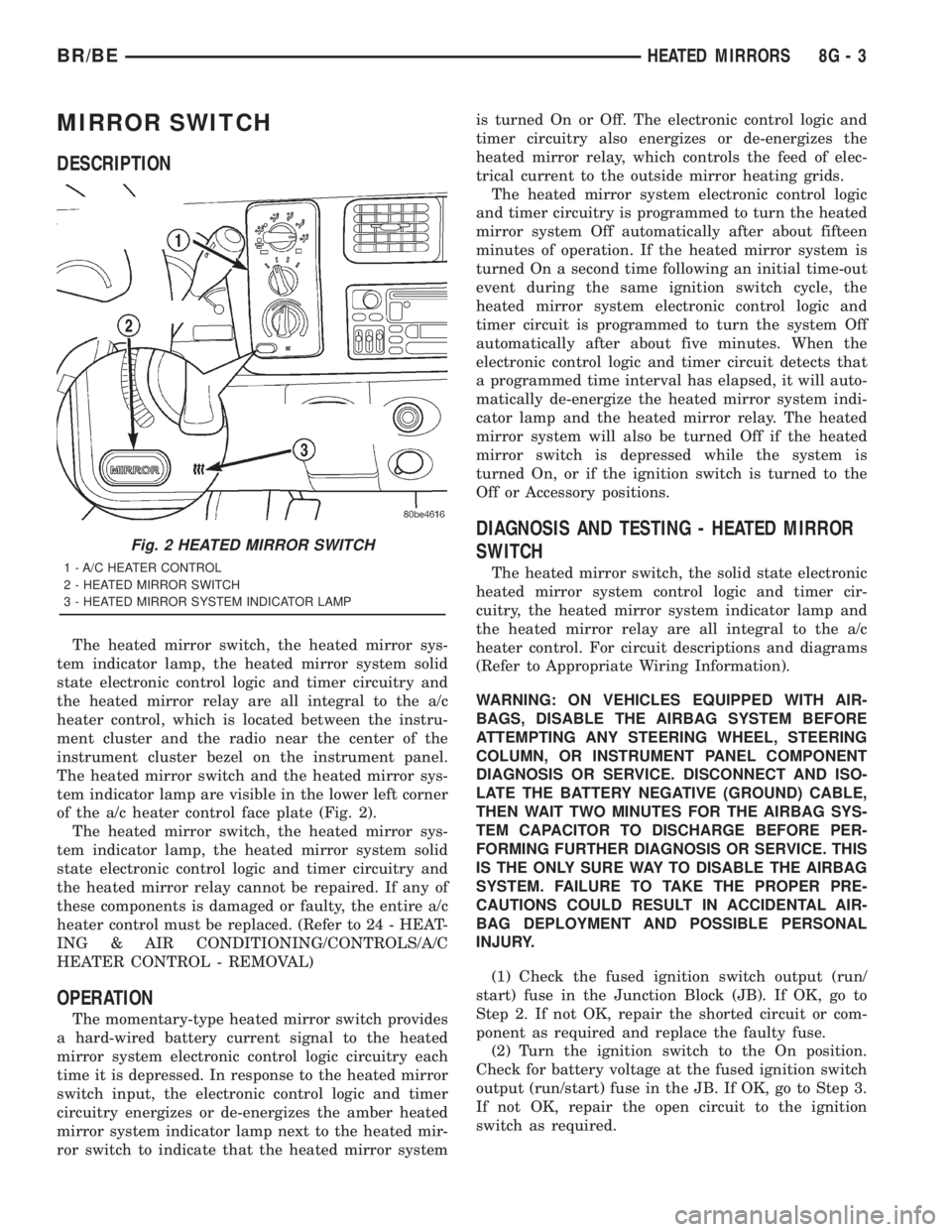
The heated mirror switch, the heated mirror sys-
tem indicator lamp, the heated mirror system solid
state electronic control logic and timer circuitry and
the heated mirror relay are all integral to the a/c
heater control, which is located between the instru-
ment cluster and the radio near the center of the
instrument cluster bezel on the instrument panel.
The heated mirror switch and the heated mirror sys-
tem indicator lamp are visible in the lower left corner
of the a/c heater control face plate (Fig. 2).
The heated mirror switch, the heated mirror sys-
tem indicator lamp, the heated mirror system solid
state electronic control logic and timer circuitry and
the heated mirror relay cannot be repaired. If any of
these components is damaged or faulty, the entire a/c
heater control must be replaced. (Refer to 24 - HEAT-
ING & AIR CONDITIONING/CONTROLS/A/C
HEATER CONTROL - REMOVAL)
OPERATION
The momentary-type heated mirror switch provides
a hard-wired battery current signal to the heated
mirror system electronic control logic circuitry each
time it is depressed. In response to the heated mirror
switch input, the electronic control logic and timer
circuitry energizes or de-energizes the amber heated
mirror system indicator lamp next to the heated mir-
ror switch to indicate that the heated mirror systemis turned On or Off. The electronic control logic and
timer circuitry also energizes or de-energizes the
heated mirror relay, which controls the feed of elec-
trical current to the outside mirror heating grids.
The heated mirror system electronic control logic
and timer circuitry is programmed to turn the heated
mirror system Off automatically after about fifteen
minutes of operation. If the heated mirror system is
turned On a second time following an initial time-out
event during the same ignition switch cycle, the
heated mirror system electronic control logic and
timer circuit is programmed to turn the system Off
automatically after about five minutes. When the
electronic control logic and timer circuit detects that
a programmed time interval has elapsed, it will auto-
matically de-energize the heated mirror system indi-
cator lamp and the heated mirror relay. The heated
mirror system will also be turned Off if the heated
mirror switch is depressed while the system is
turned On, or if the ignition switch is turned to the
Off or Accessory positions.
DIAGNOSIS AND TESTING - HEATED MIRROR
SWITCH
The heated mirror switch, the solid state electronic
heated mirror system control logic and timer cir-
cuitry, the heated mirror system indicator lamp and
the heated mirror relay are all integral to the a/c
heater control. For circuit descriptions and diagrams
(Refer to Appropriate Wiring Information).
WARNING: ON VEHICLES EQUIPPED WITH AIR-
BAGS, DISABLE THE AIRBAG SYSTEM BEFORE
ATTEMPTING ANY STEERING WHEEL, STEERING
COLUMN, OR INSTRUMENT PANEL COMPONENT
DIAGNOSIS OR SERVICE. DISCONNECT AND ISO-
LATE THE BATTERY NEGATIVE (GROUND) CABLE,
THEN WAIT TWO MINUTES FOR THE AIRBAG SYS-
TEM CAPACITOR TO DISCHARGE BEFORE PER-
FORMING FURTHER DIAGNOSIS OR SERVICE. THIS
IS THE ONLY SURE WAY TO DISABLE THE AIRBAG
SYSTEM. FAILURE TO TAKE THE PROPER PRE-
CAUTIONS COULD RESULT IN ACCIDENTAL AIR-
BAG DEPLOYMENT AND POSSIBLE PERSONAL
INJURY.
(1) Check the fused ignition switch output (run/
start) fuse in the Junction Block (JB). If OK, go to
Step 2. If not OK, repair the shorted circuit or com-
ponent as required and replace the faulty fuse.
(2) Turn the ignition switch to the On position.
Check for battery voltage at the fused ignition switch
output (run/start) fuse in the JB. If OK, go to Step 3.
If not OK, repair the open circuit to the ignition
switch as required.
Fig. 2 HEATED MIRROR SWITCH
1 - A/C HEATER CONTROL
2 - HEATED MIRROR SWITCH
3 - HEATED MIRROR SYSTEM INDICATOR LAMP
BR/BEHEATED MIRRORS 8G - 3