2001 DODGE RAM service
[x] Cancel search: servicePage 530 of 2889
Clusterin the index of this service manual for the
proper cluster illumination lamps diagnosis and test-
ing procedures. If the problem being diagnosed
involves inoperative heated seat switch indicator
lamps and the heated seat elements do not heat,
refer to Step 4. If the problem being diagnosed
involves inoperative heated seat switch indicator
lamps and the heated seat elements do heat, go to
Step 8. If the problem being diagnosed involves a
heated seat switch indicator lamp that remains illu-
minated after the heated seat has been turned Off,
refer toHeated Seat Modulein Electronic Control
Modules for the location of the proper heated seat
module diagnosis and testing procedures. Also refer
to the Body Diagnostic Manual for additional diagno-
sis and testing procedures.
(2) Disconnect and isolate the battery negative
cable. Remove the heated seat switch and bezel unit
from the instrument panel. Disconnect the instru-
ment panel wire harness connector from the connec-
tor receptacle on the back of the heated seat switch
to be tested. Check for continuity between the ground
circuit cavity of the instrument panel wire harness
connector for the heated seat switch and a good
ground. There should be continuity. If OK, go to Step
3. If not OK, repair the open ground circuit to ground
as required.
(3) Reconnect the battery negative cable. Turn the
park lamps on with the headlamp switch. Rotate the
panel lamps dimmer thumbwheel on the headlamp
switch upward to just before the interior lamps
detent. Check for battery voltage at the fused panel
lamps dimmer switch signal circuit cavity of the
instrument panel wire harness connector for the
heated seat switch. If OK, replace the faulty heated
seat switch. If not OK, repair the open fused panel
lamps dimmer switch signal circuit to the fuse in the
Junction Block (JB) as required.
(4) Check the fused ignition switch output (run)
fuse in the Junction Block (JB). If OK, go to Step 5.
If not OK, repair the shorted circuit or component as
required and replace the faulty fuse.
(5) Turn the ignition switch to the On position.
Check for battery voltage at the fused ignition switch
output (run) fuse in the JB. If OK, go to Step 6. If
not OK, repair the open fused ignition switch output
(run) circuit to the ignition switch as required.
(6) Disconnect and isolate the battery negative
cable. Remove the heated seat switch and bezel unit
from the instrument panel. Disconnect the instru-
ment panel wire harness connector from the connec-
tor receptacle on the back of the heated seat switch
to be tested. Reconnect the battery negative cable.
Turn the ignition switch to the On position. Check
for battery voltage at the fused ignition switch out-
put (run) circuit cavity of the instrument panel wireharness connector for the heated seat switch. If OK,
go to Step 7. If not OK, repair the open fused ignition
switch output (run) circuit to the JB fuse as required.
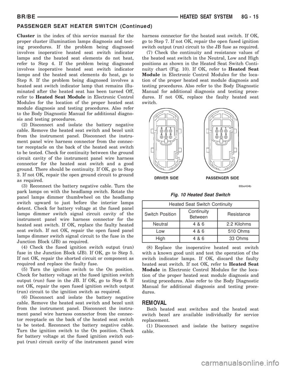
(7) Check the continuity and resistance values of
the heated seat switch in the Neutral, Low and High
positions as shown in the Heated Seat Switch Conti-
nuity chart (Fig. 10). If OK, refer toHeated Seat
Modulein Electronic Control Modules for the loca-
tion of the proper heated seat module diagnosis and
testing procedures. Also refer to the Body Diagnostic
Manual for additional diagnosis and testing proce-
dures. If not OK, replace the faulty heated seat
switch.
Heated Seat Switch Continuity
Switch PositionContinuity
BetweenResistance
Neutral 4 & 6 2.2 Kilohms
Low 4 & 6 510 Ohms
High 4 & 6 33 Ohms
(8) Replace the inoperative heated seat switch
with a known good unit and test the operation of the
switch indicator lamps. If OK, discard the faulty
heated seat switch. If not OK, refer toHeated Seat
Modulein Electronic Control Modules for the loca-
tion of the proper heated seat module diagnosis and
testing procedures. Also refer to the Body Diagnostic
Manual for additional diagnosis and testing proce-
dures.
REMOVAL
Both heated seat switches and the heated seat
switch bezel are available individually for service
replacement.
(1) Disconnect and isolate the battery negative
cable.
Fig. 10 Heated Seat Switch
BR/BEHEATED SEAT SYSTEM 8G - 15
PASSENGER SEAT HEATER SWITCH (Continued)
Page 531 of 2889
(2) Remove the cluster bezel from the instrument
panel. Refer toCluster Bezelin the index of this
service manual for the location of the proper cluster
bezel removal procedures.
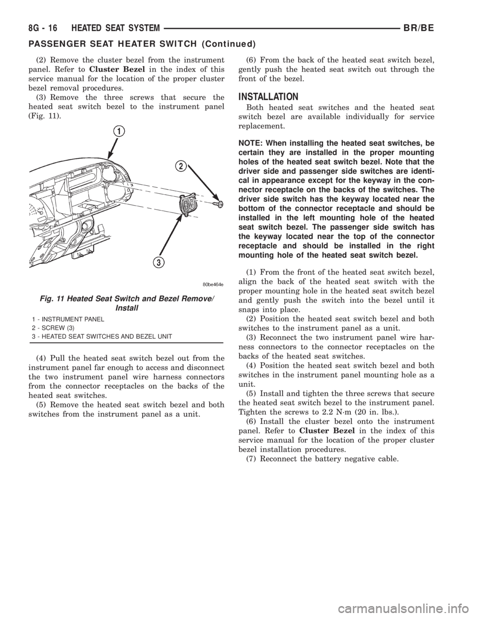
(3) Remove the three screws that secure the
heated seat switch bezel to the instrument panel
(Fig. 11).
(4) Pull the heated seat switch bezel out from the
instrument panel far enough to access and disconnect
the two instrument panel wire harness connectors
from the connector receptacles on the backs of the
heated seat switches.
(5) Remove the heated seat switch bezel and both
switches from the instrument panel as a unit.(6) From the back of the heated seat switch bezel,
gently push the heated seat switch out through the
front of the bezel.
INSTALLATION
Both heated seat switches and the heated seat
switch bezel are available individually for service
replacement.
NOTE: When installing the heated seat switches, be
certain they are installed in the proper mounting
holes of the heated seat switch bezel. Note that the
driver side and passenger side switches are identi-
cal in appearance except for the keyway in the con-
nector receptacle on the backs of the switches. The
driver side switch has the keyway located near the
bottom of the connector receptacle and should be
installed in the left mounting hole of the heated
seat switch bezel. The passenger side switch has
the keyway located near the top of the connector
receptacle and should be installed in the right
mounting hole of the heated seat switch bezel.
(1) From the front of the heated seat switch bezel,
align the back of the heated seat switch with the
proper mounting hole in the heated seat switch bezel
and gently push the switch into the bezel until it
snaps into place.
(2) Position the heated seat switch bezel and both
switches to the instrument panel as a unit.
(3) Reconnect the two instrument panel wire har-
ness connectors to the connector receptacles on the
backs of the heated seat switches.
(4) Position the heated seat switch bezel and both
switches in the instrument panel mounting hole as a
unit.
(5) Install and tighten the three screws that secure
the heated seat switch bezel to the instrument panel.
Tighten the screws to 2.2 N´m (20 in. lbs.).
(6) Install the cluster bezel onto the instrument
panel. Refer toCluster Bezelin the index of this
service manual for the location of the proper cluster
bezel installation procedures.
(7) Reconnect the battery negative cable.
Fig. 11 Heated Seat Switch and Bezel Remove/
Install
1 - INSTRUMENT PANEL
2 - SCREW (3)
3 - HEATED SEAT SWITCHES AND BEZEL UNIT
8G - 16 HEATED SEAT SYSTEMBR/BE
PASSENGER SEAT HEATER SWITCH (Continued)
Page 534 of 2889
INSTALLATION
(1) Position the horn and mounting bracket unit(s)
onto the right fender wheel house front extension.
(2) Install and tighten the screw that secures the
horn and mounting bracket unit(s) to the right
fender wheel house front extension. Tighten the
screw to 11 N´m (95 in. lbs.).
(3) Reconnect the wire harness connector(s) to the
horn connector receptacle(s).
(4) Reconnect the battery negative cable.
HORN RELAY
DESCRIPTION
The horn relay is a electromechanical device that
switches battery current to the horn when the horn
switch grounds the relay coil. The horn relay is
located in the Power Distribution Center (PDC) in
the engine compartment. If a problem is encountered
with a continuously sounding horn, it can usually be
quickly resolved by removing the horn relay from the
PDC until further diagnosis is completed. See the
fuse and relay layout label affixed to the inside sur-
face of the PDC cover for horn relay identification
and location.
The horn relay is a International Standards Orga-
nization (ISO) micro-relay. Relays conforming to the
ISO specifications have common physical dimensions,
current capacities, terminal patterns, and terminal
functions. The ISO micro-relay terminal functions
are the same as a conventional ISO relay. However,
the ISO micro-relay terminal pattern (or footprint) is
different, the current capacity is lower, and the phys-
ical dimensions are smaller than those of the conven-
tional ISO relay.
The horn relay cannot be repaired or adjusted and,
if faulty or damaged, it must be replaced.
OPERATION
The ISO relay consists of an electromagnetic coil, a
resistor or diode, and three (two fixed and one mov-
able) electrical contacts. The movable (common feed)
relay contact is held against one of the fixed contacts
(normally closed) by spring pressure. When the elec-
tromagnetic coil is energized, it draws the movable
contact away from the normally closed fixed contact,
and holds it against the other (normally open) fixed
contact.
When the electromagnetic coil is de-energized,
spring pressure returns the movable contact to the
normally closed position. The resistor or diode is con-
nected in parallel with the electromagnetic coil in the
relay, and helps to dissipate voltage spikes that are
produced when the coil is de-energized.
DIAGNOSIS AND TESTING
DIAGNOSIS AND TESTING - HORN RELAY
The horn relay (Fig. 2) is located in the Power Dis-
tribution Center (PDC) behind the battery on the
driver side of the engine compartment. If a problem
is encountered with a continuously sounding horn, it
can usually be quickly resolved by removing the horn
relay from the PDC until further diagnosis is com-
pleted. See the fuse and relay layout label affixed to
the inside surface of the PDC cover for horn relay
identification and location. For complete circuit dia-
grams, refer to the appropriate wiring information.
The wiring information includes wiring diagrams,
proper wire and connector repair procedures, details
of wire harness routing and retention, connector pin-
out information and location views for the various
wire harness connectors, splices and grounds.
WARNING: ON VEHICLES EQUIPPED WITH AIR-
BAGS, REFER TO ELECTRICAL, RESTRAINTS
BEFORE ATTEMPTING ANY STEERING WHEEL,
STEERING COLUMN, OR INSTRUMENT PANEL
COMPONENT DIAGNOSIS OR SERVICE. FAILURE
TO TAKE THE PROPER PRECAUTIONS COULD
RESULT IN ACCIDENTAL AIRBAG DEPLOYMENT
AND POSSIBLE PERSONAL INJURY.
(1) Remove the horn relay from the PDC. (Refer to
8 - ELECTRICAL/HORN/HORN RELAY -
REMOVAL) for the procedures.
(2) A relay in the de-energized position should
have continuity between terminals 87A and 30, and
no continuity between terminals 87 and 30. If OK, go
to Step 3. If not OK, replace the faulty relay.
(3) Resistance between terminals 85 and 86 (elec-
tromagnet) should be 7565 ohms. If OK, go to Step
4. If not OK, replace the faulty relay.
(4) Connect a battery to terminals 85 and 86.
There should now be continuity between terminals
30 and 87, and no continuity between terminals 87A
and 30. If OK, perform the Relay Circuit Test that
follows. If not OK, replace the faulty relay.
RELAY CIRCUIT TEST
(1) The relay common feed terminal cavity (30) is
connected to battery voltage and should be hot at all
times. If OK, go to Step 2. If not OK, repair the open
circuit to the fuse in the PDC as required.
(2) The relay normally closed terminal (87A) is
connected to terminal 30 in the de-energized position,
but is not used for this application. Go to Step 3.
BR/BEHORN 8H - 3
HORN (Continued)
Page 536 of 2889
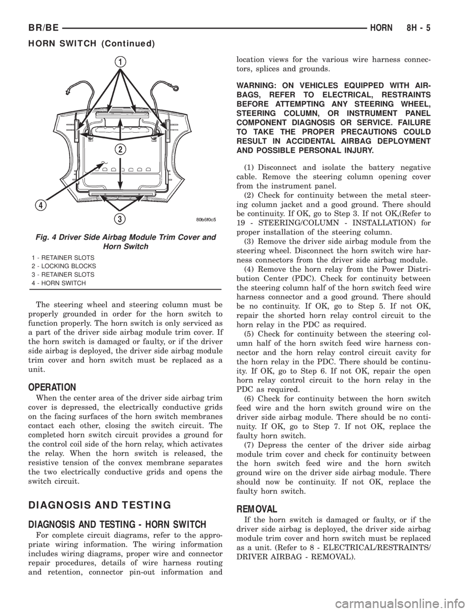
The steering wheel and steering column must be
properly grounded in order for the horn switch to
function properly. The horn switch is only serviced as
a part of the driver side airbag module trim cover. If
the horn switch is damaged or faulty, or if the driver
side airbag is deployed, the driver side airbag module
trim cover and horn switch must be replaced as a
unit.
OPERATION
When the center area of the driver side airbag trim
cover is depressed, the electrically conductive grids
on the facing surfaces of the horn switch membranes
contact each other, closing the switch circuit. The
completed horn switch circuit provides a ground for
the control coil side of the horn relay, which activates
the relay. When the horn switch is released, the
resistive tension of the convex membrane separates
the two electrically conductive grids and opens the
switch circuit.
DIAGNOSIS AND TESTING
DIAGNOSIS AND TESTING - HORN SWITCH
For complete circuit diagrams, refer to the appro-
priate wiring information. The wiring information
includes wiring diagrams, proper wire and connector
repair procedures, details of wire harness routing
and retention, connector pin-out information andlocation views for the various wire harness connec-
tors, splices and grounds.
WARNING: ON VEHICLES EQUIPPED WITH AIR-
BAGS, REFER TO ELECTRICAL, RESTRAINTS
BEFORE ATTEMPTING ANY STEERING WHEEL,
STEERING COLUMN, OR INSTRUMENT PANEL
COMPONENT DIAGNOSIS OR SERVICE. FAILURE
TO TAKE THE PROPER PRECAUTIONS COULD
RESULT IN ACCIDENTAL AIRBAG DEPLOYMENT
AND POSSIBLE PERSONAL INJURY.
(1) Disconnect and isolate the battery negative
cable. Remove the steering column opening cover
from the instrument panel.
(2) Check for continuity between the metal steer-
ing column jacket and a good ground. There should
be continuity. If OK, go to Step 3. If not OK,(Refer to
19 - STEERING/COLUMN - INSTALLATION) for
proper installation of the steering column.
(3) Remove the driver side airbag module from the
steering wheel. Disconnect the horn switch wire har-
ness connectors from the driver side airbag module.
(4) Remove the horn relay from the Power Distri-
bution Center (PDC). Check for continuity between
the steering column half of the horn switch feed wire
harness connector and a good ground. There should
be no continuity. If OK, go to Step 5. If not OK,
repair the shorted horn relay control circuit to the
horn relay in the PDC as required.
(5) Check for continuity between the steering col-
umn half of the horn switch feed wire harness con-
nector and the horn relay control circuit cavity for
the horn relay in the PDC. There should be continu-
ity. If OK, go to Step 6. If not OK, repair the open
horn relay control circuit to the horn relay in the
PDC as required.
(6) Check for continuity between the horn switch
feed wire and the horn switch ground wire on the
driver side airbag module. There should be no conti-
nuity. If OK, go to Step 7. If not OK, replace the
faulty horn switch.
(7) Depress the center of the driver side airbag
module trim cover and check for continuity between
the horn switch feed wire and the horn switch
ground wire on the driver side airbag module. There
should now be continuity. If not OK, replace the
faulty horn switch.
REMOVAL
If the horn switch is damaged or faulty, or if the
driver side airbag is deployed, the driver side airbag
module trim cover and horn switch must be replaced
as a unit. (Refer to 8 - ELECTRICAL/RESTRAINTS/
DRIVER AIRBAG - REMOVAL).
Fig. 4 Driver Side Airbag Module Trim Cover and
Horn Switch
1 - RETAINER SLOTS
2 - LOCKING BLOCKS
3 - RETAINER SLOTS
4 - HORN SWITCH
BR/BEHORN 8H - 5
HORN SWITCH (Continued)
Page 548 of 2889

OPERATION
The camshaft position sensor provides fuel injec-
tion synchronization and cylinder identification.
The distributor does not have built in centrifugal
or vacuum assisted advance. Base ignition timing
and all timing advance is controlled by the Power-
train Control Module (PCM). Because ignition timing
is controlled by the PCM,base ignition timing is
not adjustable.
The distributor is held to the engine in the conven-
tional method using a holddown clamp and bolt.
Although the distributor can be rotated, it will
have no effect on ignition timing.
All distributors contain an internal oil seal that
prevents oil from entering the distributor housing.
The seal is not serviceable.
REMOVAL
CAUTION: Base ignition timing is not adjustable on
any engine. Distributors do not have built in centrif-
ugal or vacuum assisted advance. Base ignition
timing and timing advance are controlled by the
Powertrain Control Module (PCM). Because a con-
ventional timing light can not be used to adjust dis-
tributor position after installation, note position of
distributor before removal.
(1) Remove air cleaner assembly.
(2) Disconnect negative cable from battery.
(3) Remove distributor cap from distributor (two
screws).
(4) Mark the position of distributor housing in
relationship to engine or dash panel. This is done to
aid in installation.(5) Before distributor is removed, the number one
cylinder must be brought to the Top Dead Center
(TDC) firing position.
(6) Attach a socket to the Crankshaft Vibration
Damper mounting bolt.
(7) Slowly rotate engine clockwise, as viewed from
front, until indicating mark on crankshaft vibration
damper is aligned to 0 degree (TDC) mark on timing
chain cover (Fig. 18).
(8) The distributor rotor should now be aligned to
the CYL. NO. 1 alignment mark (stamped) into the
camshaft position sensor (Fig. 19). If not, rotate the
crankshaft through another complete 360 degree
turn. Note the position of the number one cylinder
spark plug cable (on the cap) in relation to rotor.
Rotor should now be aligned to this position.
(9) Disconnect camshaft position sensor wiring
harness from main engine wiring harness.
(10) Remove distributor rotor from distributor
shaft.
(11) Remove distributor holddown clamp bolt and
clamp (Fig. 20). Remove distributor from vehicle.
CAUTION: Do not crank engine with distributor
removed. Distributor/crankshaft relationship will be
lost.
INSTALLATION
If engine has been cranked while distributor is
removed, establish the relationship between distribu-
tor shaft and number one piston position as follows:
Rotate crankshaft in a clockwise direction, as
viewed from front, until number one cylinder piston
is at top of compression stroke (compression should
be felt on finger with number one spark plug
Fig. 17 Distributor and Camshaft Position Sensor
1 - SYNC SIGNAL GENERATOR
2 - CAMSHAFT POSITION SENSOR
3 - PULSE RING
4 - DISTRIBUTOR ASSEMBLY
Fig. 18 Damper-To-Cover Alignment MarksÐTypical
1 - ALIGNMENT MARK
2 - TIMING CHAIN COVER MARKS
3 - CRANKSHAFT VIBRATION DAMPER
BR/BEIGNITION CONTROL 8I - 11
DISTRIBUTOR (Continued)
Page 552 of 2889
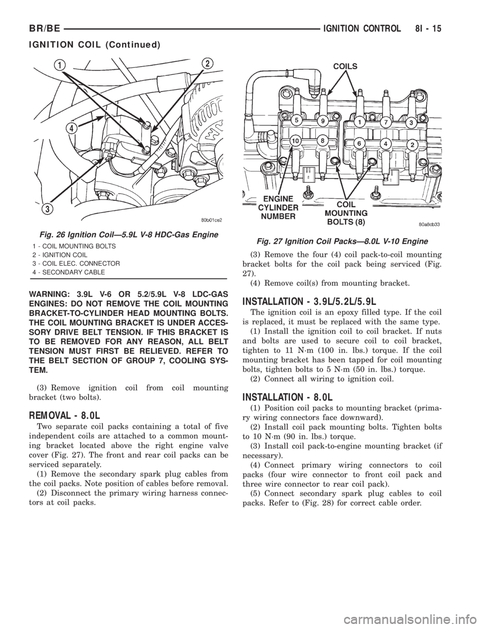
WARNING: 3.9L V-6 OR 5.2/5.9L V-8 LDC-GAS
ENGINES: DO NOT REMOVE THE COIL MOUNTING
BRACKET-TO-CYLINDER HEAD MOUNTING BOLTS.
THE COIL MOUNTING BRACKET IS UNDER ACCES-
SORY DRIVE BELT TENSION. IF THIS BRACKET IS
TO BE REMOVED FOR ANY REASON, ALL BELT
TENSION MUST FIRST BE RELIEVED. REFER TO
THE BELT SECTION OF GROUP 7, COOLING SYS-
TEM.
(3) Remove ignition coil from coil mounting
bracket (two bolts).
REMOVAL - 8.0L
Two separate coil packs containing a total of five
independent coils are attached to a common mount-
ing bracket located above the right engine valve
cover (Fig. 27). The front and rear coil packs can be
serviced separately.
(1) Remove the secondary spark plug cables from
the coil packs. Note position of cables before removal.
(2) Disconnect the primary wiring harness connec-
tors at coil packs.(3) Remove the four (4) coil pack-to-coil mounting
bracket bolts for the coil pack being serviced (Fig.
27).
(4) Remove coil(s) from mounting bracket.
INSTALLATION - 3.9L/5.2L/5.9L
The ignition coil is an epoxy filled type. If the coil
is replaced, it must be replaced with the same type.
(1) Install the ignition coil to coil bracket. If nuts
and bolts are used to secure coil to coil bracket,
tighten to 11 N´m (100 in. lbs.) torque. If the coil
mounting bracket has been tapped for coil mounting
bolts, tighten bolts to 5 N´m (50 in. lbs.) torque.
(2) Connect all wiring to ignition coil.
INSTALLATION - 8.0L
(1) Position coil packs to mounting bracket (prima-
ry wiring connectors face downward).
(2) Install coil pack mounting bolts. Tighten bolts
to 10 N´m (90 in. lbs.) torque.
(3) Install coil pack-to-engine mounting bracket (if
necessary).
(4) Connect primary wiring connectors to coil
packs (four wire connector to front coil pack and
three wire connector to rear coil pack).
(5) Connect secondary spark plug cables to coil
packs. Refer to (Fig. 28) for correct cable order.
Fig. 26 Ignition CoilÐ5.9L V-8 HDC-Gas Engine
1 - COIL MOUNTING BOLTS
2 - IGNITION COIL
3 - COIL ELEC. CONNECTOR
4 - SECONDARY CABLEFig. 27 Ignition Coil PacksÐ8.0L V-10 Engine
BR/BEIGNITION CONTROL 8I - 15
IGNITION COIL (Continued)
Page 560 of 2889
INSTRUMENT CLUSTER
TABLE OF CONTENTS
page page
INSTRUMENT CLUSTER
DESCRIPTION............................2
OPERATION.............................3
DIAGNOSIS AND TESTING..................6
INSTRUMENT CLUSTER..................6
REMOVAL..............................10
DISASSEMBLY...........................11
ASSEMBLY.............................13
INSTALLATION...........................14
ABS INDICATOR
DESCRIPTION...........................14
OPERATION.............................14
AIRBAG INDICATOR
DESCRIPTION...........................15
OPERATION.............................15
BRAKE/PARK BRAKE INDICATOR
DESCRIPTION...........................16
OPERATION.............................16
DIAGNOSIS AND TESTING.................16
BRAKE INDICATOR.....................16
CHECK GAUGES INDICATOR
DESCRIPTION...........................17
OPERATION.............................17
CRUISE INDICATOR
DESCRIPTION...........................18
OPERATION.............................18
ENGINE TEMPERATURE GAUGE
DESCRIPTION...........................19
OPERATION.............................19
FUEL GAUGE
DESCRIPTION...........................20
OPERATION.............................20
GEAR SELECTOR INDICATOR
DESCRIPTION...........................21
OPERATION.............................21
HIGH BEAM INDICATOR
DESCRIPTION...........................21
OPERATION.............................22
DIAGNOSIS AND TESTING.................22
HIGH BEAM INDICATOR.................22
LOW FUEL INDICATOR
DESCRIPTION...........................23
OPERATION.............................23
MALFUNCTION INDICATOR LAMP (MIL)
DESCRIPTION...........................24
OPERATION.............................24
ODOMETER
DESCRIPTION...........................24
OPERATION.............................25OIL PRESSURE GAUGE
DESCRIPTION...........................25
OPERATION.............................26
OVERDRIVE OFF INDICATOR
DESCRIPTION...........................27
OPERATION.............................27
SEATBELT INDICATOR
DESCRIPTION...........................27
OPERATION.............................27
SERVICE REMINDER INDICATOR
DESCRIPTION...........................28
OPERATION.............................28
SHIFT INDICATOR (TRANSFER CASE)
DESCRIPTION...........................29
OPERATION.............................29
DIAGNOSIS AND TESTING.................29
FOUR-WHEEL DRIVE INDICATOR..........29
SPEEDOMETER
DESCRIPTION...........................30
OPERATION.............................30
TACHOMETER
DESCRIPTION...........................30
OPERATION.............................31
TRANSMISSION OVERTEMP INDICATOR
DESCRIPTION...........................31
OPERATION.............................31
TURN SIGNAL INDICATORS
DESCRIPTION...........................32
OPERATION.............................32
DIAGNOSIS AND TESTING.................32
TURN SIGNAL INDICATORS..............32
UPSHIFT INDICATOR
DESCRIPTION...........................33
OPERATION.............................33
VOLTAGE GAUGE
DESCRIPTION...........................33
OPERATION.............................34
WAIT-TO-START INDICATOR
DESCRIPTION...........................34
OPERATION.............................35
WASHER FLUID INDICATOR
DESCRIPTION...........................35
OPERATION.............................35
DIAGNOSIS AND TESTING.................36
WASHER FLUID INDICATOR..............36
WATER-IN-FUEL INDICATOR
DESCRIPTION...........................36
OPERATION.............................37
BR/BEINSTRUMENT CLUSTER 8J - 1
Page 561 of 2889
INSTRUMENT CLUSTER
DESCRIPTION
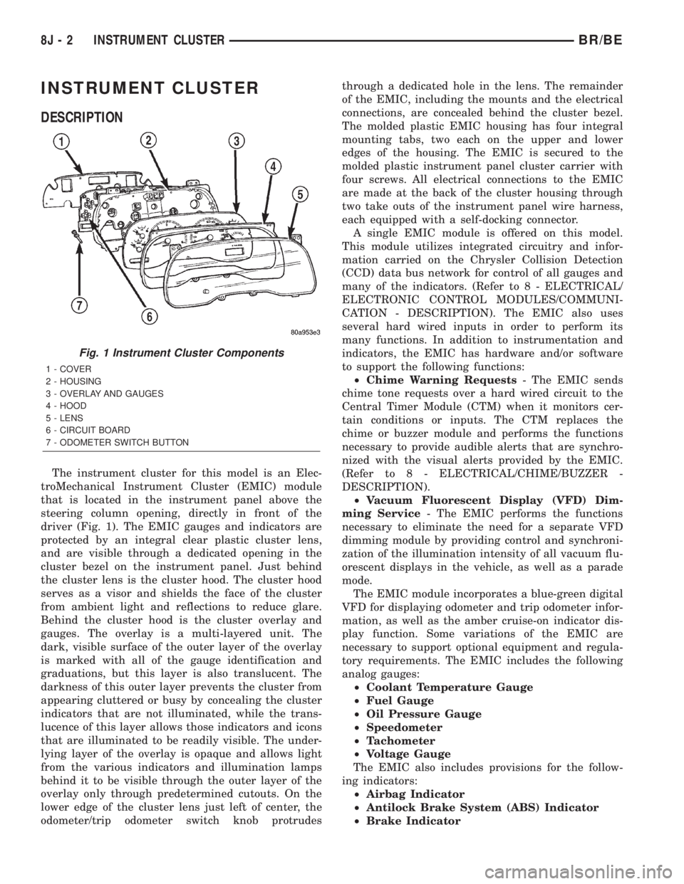
The instrument cluster for this model is an Elec-
troMechanical Instrument Cluster (EMIC) module
that is located in the instrument panel above the
steering column opening, directly in front of the
driver (Fig. 1). The EMIC gauges and indicators are
protected by an integral clear plastic cluster lens,
and are visible through a dedicated opening in the
cluster bezel on the instrument panel. Just behind
the cluster lens is the cluster hood. The cluster hood
serves as a visor and shields the face of the cluster
from ambient light and reflections to reduce glare.
Behind the cluster hood is the cluster overlay and
gauges. The overlay is a multi-layered unit. The
dark, visible surface of the outer layer of the overlay
is marked with all of the gauge identification and
graduations, but this layer is also translucent. The
darkness of this outer layer prevents the cluster from
appearing cluttered or busy by concealing the cluster
indicators that are not illuminated, while the trans-
lucence of this layer allows those indicators and icons
that are illuminated to be readily visible. The under-
lying layer of the overlay is opaque and allows light
from the various indicators and illumination lamps
behind it to be visible through the outer layer of the
overlay only through predetermined cutouts. On the
lower edge of the cluster lens just left of center, the
odometer/trip odometer switch knob protrudesthrough a dedicated hole in the lens. The remainder
of the EMIC, including the mounts and the electrical
connections, are concealed behind the cluster bezel.
The molded plastic EMIC housing has four integral
mounting tabs, two each on the upper and lower
edges of the housing. The EMIC is secured to the
molded plastic instrument panel cluster carrier with
four screws. All electrical connections to the EMIC
are made at the back of the cluster housing through
two take outs of the instrument panel wire harness,
each equipped with a self-docking connector.
A single EMIC module is offered on this model.
This module utilizes integrated circuitry and infor-
mation carried on the Chrysler Collision Detection
(CCD) data bus network for control of all gauges and
many of the indicators. (Refer to 8 - ELECTRICAL/
ELECTRONIC CONTROL MODULES/COMMUNI-
CATION - DESCRIPTION). The EMIC also uses
several hard wired inputs in order to perform its
many functions. In addition to instrumentation and
indicators, the EMIC has hardware and/or software
to support the following functions:
²Chime Warning Requests- The EMIC sends
chime tone requests over a hard wired circuit to the
Central Timer Module (CTM) when it monitors cer-
tain conditions or inputs. The CTM replaces the
chime or buzzer module and performs the functions
necessary to provide audible alerts that are synchro-
nized with the visual alerts provided by the EMIC.
(Refer to 8 - ELECTRICAL/CHIME/BUZZER -
DESCRIPTION).
²Vacuum Fluorescent Display (VFD) Dim-
ming Service- The EMIC performs the functions
necessary to eliminate the need for a separate VFD
dimming module by providing control and synchroni-
zation of the illumination intensity of all vacuum flu-
orescent displays in the vehicle, as well as a parade
mode.
The EMIC module incorporates a blue-green digital
VFD for displaying odometer and trip odometer infor-
mation, as well as the amber cruise-on indicator dis-
play function. Some variations of the EMIC are
necessary to support optional equipment and regula-
tory requirements. The EMIC includes the following
analog gauges:
²Coolant Temperature Gauge
²Fuel Gauge
²Oil Pressure Gauge
²Speedometer
²Tachometer
²Voltage Gauge
The EMIC also includes provisions for the follow-
ing indicators:
²Airbag Indicator
²Antilock Brake System (ABS) Indicator
²Brake Indicator
Fig. 1 Instrument Cluster Components
1 - COVER
2 - HOUSING
3 - OVERLAY AND GAUGES
4 - HOOD
5 - LENS
6 - CIRCUIT BOARD
7 - ODOMETER SWITCH BUTTON
8J - 2 INSTRUMENT CLUSTERBR/BE