2001 DODGE RAM service
[x] Cancel search: servicePage 355 of 2889
REMOVAL
WARNING: BECAUSE OF HIGH SPRING PRES-
SURE, DO NOT ATTEMPT TO DISASSEMBLE AUTO-
MATIC TENSIONER. UNIT IS SERVICED AS AN
ASSEMBLY (EXCEPT FOR PULLEY).
(1) Remove accessory drive belt. (Refer to 7 -
COOLING/ACCESSORY DRIVE/DRIVE BELTS -
REMOVAL).
(2) Disconnect wiring and secondary cable from
ignition coil.
(3) Remove ignition coil from coil mounting
bracket (two bolts). Do not remove coil mounting
bracket from cylinder head.
(4) Remove tensioner assembly from mounting
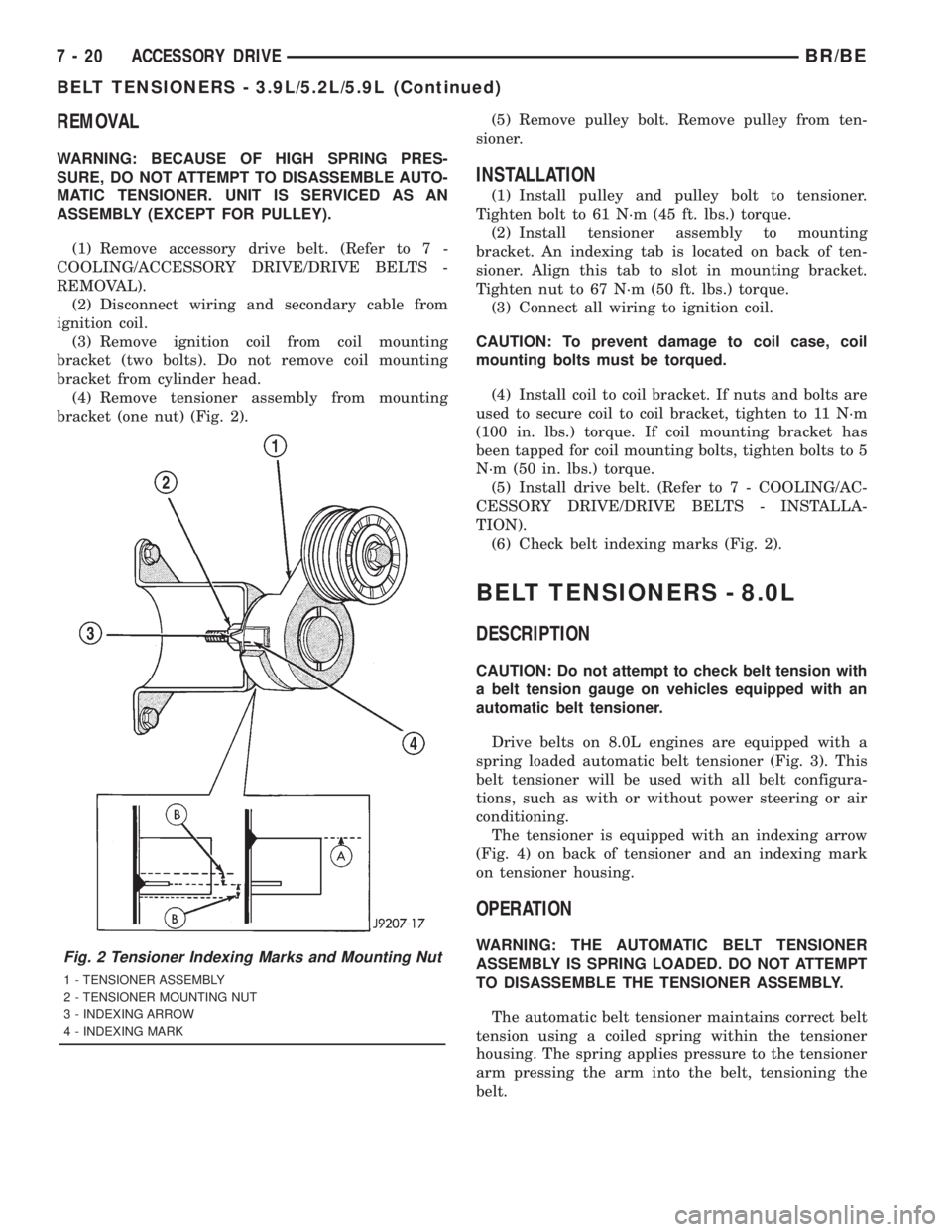
bracket (one nut) (Fig. 2).(5) Remove pulley bolt. Remove pulley from ten-
sioner.
INSTALLATION
(1) Install pulley and pulley bolt to tensioner.
Tighten bolt to 61 N´m (45 ft. lbs.) torque.
(2) Install tensioner assembly to mounting
bracket. An indexing tab is located on back of ten-
sioner. Align this tab to slot in mounting bracket.
Tighten nut to 67 N´m (50 ft. lbs.) torque.
(3) Connect all wiring to ignition coil.
CAUTION: To prevent damage to coil case, coil
mounting bolts must be torqued.
(4) Install coil to coil bracket. If nuts and bolts are
used to secure coil to coil bracket, tighten to 11 N´m
(100 in. lbs.) torque. If coil mounting bracket has
been tapped for coil mounting bolts, tighten bolts to 5
N´m (50 in. lbs.) torque.
(5) Install drive belt. (Refer to 7 - COOLING/AC-
CESSORY DRIVE/DRIVE BELTS - INSTALLA-
TION).
(6) Check belt indexing marks (Fig. 2).
BELT TENSIONERS - 8.0L
DESCRIPTION
CAUTION: Do not attempt to check belt tension with
a belt tension gauge on vehicles equipped with an
automatic belt tensioner.
Drive belts on 8.0L engines are equipped with a
spring loaded automatic belt tensioner (Fig. 3). This
belt tensioner will be used with all belt configura-
tions, such as with or without power steering or air
conditioning.
The tensioner is equipped with an indexing arrow
(Fig. 4) on back of tensioner and an indexing mark
on tensioner housing.
OPERATION
WARNING: THE AUTOMATIC BELT TENSIONER
ASSEMBLY IS SPRING LOADED. DO NOT ATTEMPT
TO DISASSEMBLE THE TENSIONER ASSEMBLY.
The automatic belt tensioner maintains correct belt
tension using a coiled spring within the tensioner
housing. The spring applies pressure to the tensioner
arm pressing the arm into the belt, tensioning the
belt.Fig. 2 Tensioner Indexing Marks and Mounting Nut
1 - TENSIONER ASSEMBLY
2 - TENSIONER MOUNTING NUT
3 - INDEXING ARROW
4 - INDEXING MARK
7 - 20 ACCESSORY DRIVEBR/BE
BELT TENSIONERS - 3.9L/5.2L/5.9L (Continued)
Page 356 of 2889
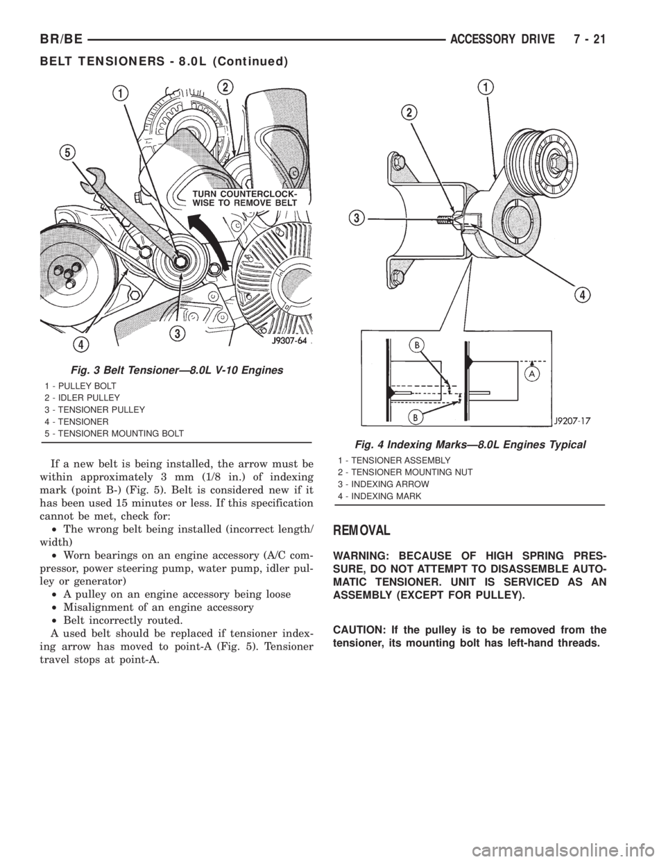
If a new belt is being installed, the arrow must be
within approximately 3 mm (1/8 in.) of indexing
mark (point B-) (Fig. 5). Belt is considered new if it
has been used 15 minutes or less. If this specification
cannot be met, check for:
²The wrong belt being installed (incorrect length/
width)
²Worn bearings on an engine accessory (A/C com-
pressor, power steering pump, water pump, idler pul-
ley or generator)
²A pulley on an engine accessory being loose
²Misalignment of an engine accessory
²Belt incorrectly routed.
A used belt should be replaced if tensioner index-
ing arrow has moved to point-A (Fig. 5). Tensioner
travel stops at point-A.
REMOVAL
WARNING: BECAUSE OF HIGH SPRING PRES-
SURE, DO NOT ATTEMPT TO DISASSEMBLE AUTO-
MATIC TENSIONER. UNIT IS SERVICED AS AN
ASSEMBLY (EXCEPT FOR PULLEY).
CAUTION: If the pulley is to be removed from the
tensioner, its mounting bolt has left-hand threads.
Fig. 3 Belt TensionerÐ8.0L V-10 Engines
1 - PULLEY BOLT
2 - IDLER PULLEY
3 - TENSIONER PULLEY
4 - TENSIONER
5 - TENSIONER MOUNTING BOLT
Fig. 4 Indexing MarksÐ8.0L Engines Typical
1 - TENSIONER ASSEMBLY
2 - TENSIONER MOUNTING NUT
3 - INDEXING ARROW
4 - INDEXING MARK
BR/BEACCESSORY DRIVE 7 - 21
BELT TENSIONERS - 8.0L (Continued)
Page 358 of 2889
BELT TENSIONERS - 5.9L
DIESEL
DESCRIPTION
Drive belts on all engines are equipped with a
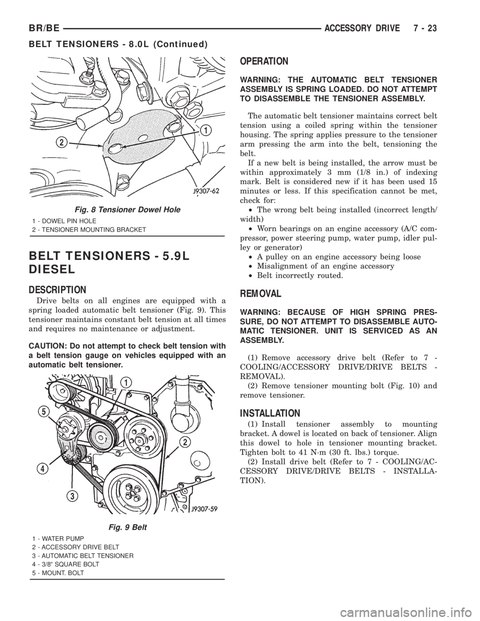
spring loaded automatic belt tensioner (Fig. 9). This
tensioner maintains constant belt tension at all times
and requires no maintenance or adjustment.
CAUTION: Do not attempt to check belt tension with
a belt tension gauge on vehicles equipped with an
automatic belt tensioner.
OPERATION
WARNING: THE AUTOMATIC BELT TENSIONER
ASSEMBLY IS SPRING LOADED. DO NOT ATTEMPT
TO DISASSEMBLE THE TENSIONER ASSEMBLY.
The automatic belt tensioner maintains correct belt
tension using a coiled spring within the tensioner
housing. The spring applies pressure to the tensioner
arm pressing the arm into the belt, tensioning the
belt.
If a new belt is being installed, the arrow must be
within approximately 3 mm (1/8 in.) of indexing
mark. Belt is considered new if it has been used 15
minutes or less. If this specification cannot be met,
check for:
²The wrong belt being installed (incorrect length/
width)
²Worn bearings on an engine accessory (A/C com-
pressor, power steering pump, water pump, idler pul-
ley or generator)
²A pulley on an engine accessory being loose
²Misalignment of an engine accessory
²Belt incorrectly routed.
REMOVAL
WARNING: BECAUSE OF HIGH SPRING PRES-
SURE, DO NOT ATTEMPT TO DISASSEMBLE AUTO-
MATIC TENSIONER. UNIT IS SERVICED AS AN
ASSEMBLY.
(1) Remove accessory drive belt (Refer to 7 -
COOLING/ACCESSORY DRIVE/DRIVE BELTS -
REMOVAL).
(2) Remove tensioner mounting bolt (Fig. 10) and
remove tensioner.
INSTALLATION
(1) Install tensioner assembly to mounting
bracket. A dowel is located on back of tensioner. Align
this dowel to hole in tensioner mounting bracket.
Tighten bolt to 41 N´m (30 ft. lbs.) torque.
(2) Install drive belt (Refer to 7 - COOLING/AC-
CESSORY DRIVE/DRIVE BELTS - INSTALLA-
TION).
Fig. 8 Tensioner Dowel Hole
1 - DOWEL PIN HOLE
2 - TENSIONER MOUNTING BRACKET
Fig. 9 Belt
1 - WATER PUMP
2 - ACCESSORY DRIVE BELT
3 - AUTOMATIC BELT TENSIONER
4 - 3/89SQUARE BOLT
5 - MOUNT. BOLT
BR/BEACCESSORY DRIVE 7 - 23
BELT TENSIONERS - 8.0L (Continued)
Page 370 of 2889
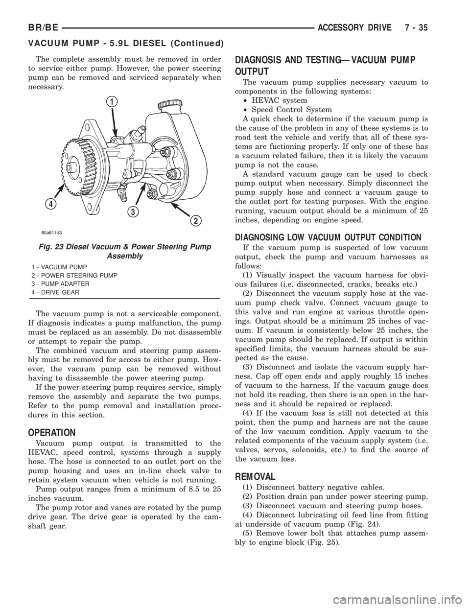
The complete assembly must be removed in order
to service either pump. However, the power steering
pump can be removed and serviced separately when
necessary.
The vacuum pump is not a serviceable component.
If diagnosis indicates a pump malfunction, the pump
must be replaced as an assembly. Do not disassemble
or attempt to repair the pump.
The combined vacuum and steering pump assem-
bly must be removed for access to either pump. How-
ever, the vacuum pump can be removed without
having to disassemble the power steering pump.
If the power steering pump requires service, simply
remove the assembly and separate the two pumps.
Refer to the pump removal and installation proce-
dures in this section.
OPERATION
Vacuum pump output is transmitted to the
HEVAC, speed control, systems through a supply
hose. The hose is connected to an outlet port on the
pump housing and uses an in-line check valve to
retain system vacuum when vehicle is not running.
Pump output ranges from a minimum of 8.5 to 25
inches vacuum.
The pump rotor and vanes are rotated by the pump
drive gear. The drive gear is operated by the cam-
shaft gear.
DIAGNOSIS AND TESTINGÐVACUUM PUMP
OUTPUT
The vacuum pump supplies necessary vacuum to
components in the following systems:
²HEVAC system
²Speed Control System
A quick check to determine if the vacuum pump is
the cause of the problem in any of these systems is to
road test the vehicle and verify that all of these sys-
tems are fuctioning properly. If only one of these has
a vacuum related failure, then it is likely the vacuum
pump is not the cause.
A standard vacuum gauge can be used to check
pump output when necessary. Simply disconnect the
pump supply hose and connect a vacuum gauge to
the outlet port for testing purposes. With the engine
running, vacuum output should be a minimum of 25
inches, depending on engine speed.
DIAGNOSING LOW VACUUM OUTPUT CONDITION
If the vacuum pump is suspected of low vacuum
output, check the pump and vacuum harnesses as
follows:
(1) Visually inspect the vacuum harness for obvi-
ous failures (i.e. disconnected, cracks, breaks etc.)
(2) Disconnect the vacuum supply hose at the vac-
uum pump check valve. Connect vacuum gauge to
this valve and run engine at various throttle open-
ings. Output should be a minimum 25 inches of vac-
uum. If vacuum is consistently below 25 inches, the
vacuum pump should be replaced. If output is within
specified limits, the vacuum harness should be sus-
pected as the cause.
(3) Disconnect and isolate the vacuum supply har-
ness. Cap off open ends and apply roughly 15 inches
of vacuum to the harness. If the vacuum gauge does
not hold its reading, then there is an open in the har-
ness and it should be repaired or replaced.
(4) If the vacuum loss is still not detected at this
point, then the pump and harness are not the cause
of the low vacuum condition. Apply vacuum to the
related components of the vacuum supply system (i.e.
valves, servos, solenoids, etc.) to find the source of
the vacuum loss.
REMOVAL
(1) Disconnect battery negative cables.
(2) Position drain pan under power steering pump.
(3) Disconnect vacuum and steering pump hoses.
(4) Disconnect lubricating oil feed line from fitting
at underside of vacuum pump (Fig. 24).
(5) Remove lower bolt that attaches pump assem-
bly to engine block (Fig. 25).
Fig. 23 Diesel Vacuum & Power Steering Pump
Assembly
1 - VACUUM PUMP
2 - POWER STEERING PUMP
3 - PUMP ADAPTER
4 - DRIVE GEAR
BR/BEACCESSORY DRIVE 7 - 35
VACUUM PUMP - 5.9L DIESEL (Continued)
Page 371 of 2889
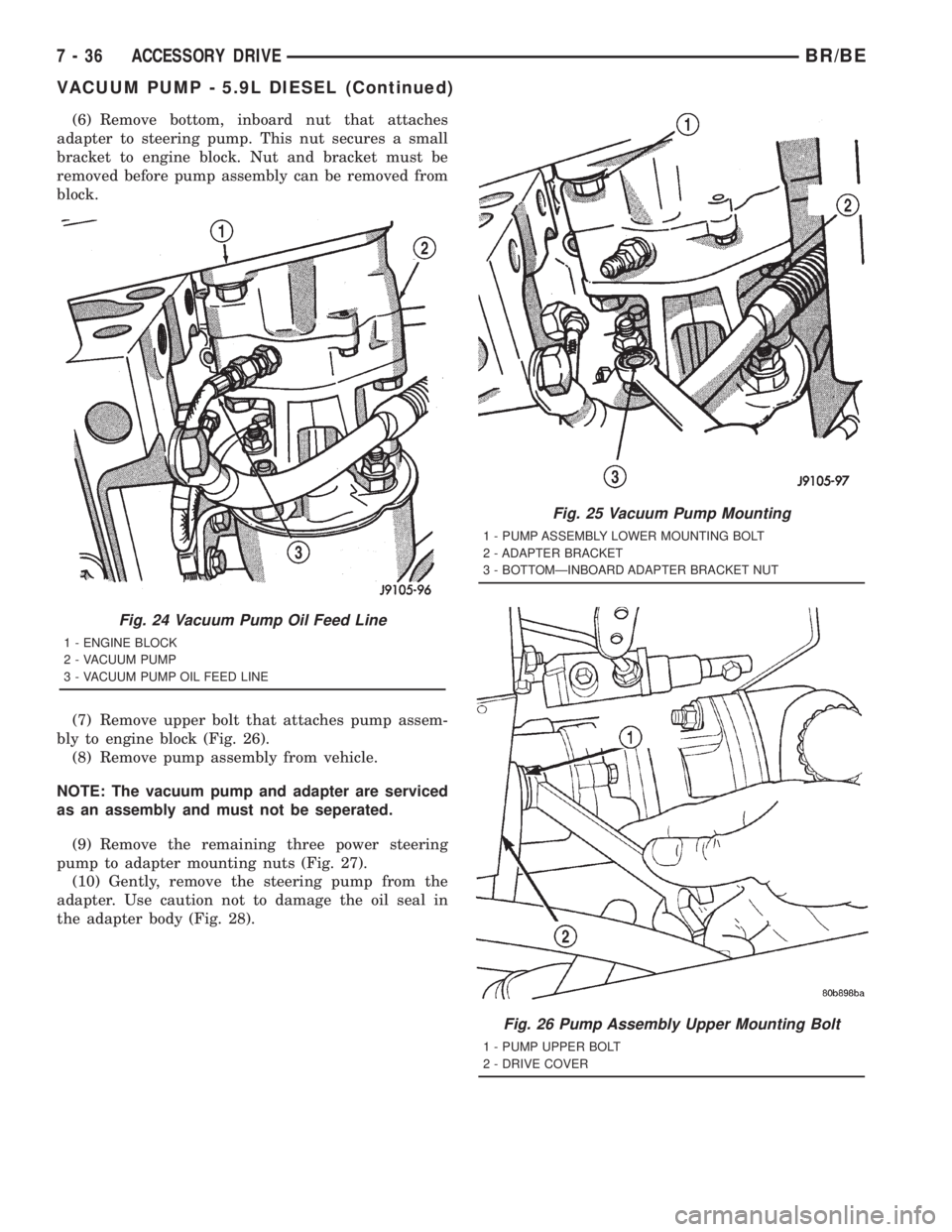
(6) Remove bottom, inboard nut that attaches
adapter to steering pump. This nut secures a small
bracket to engine block. Nut and bracket must be
removed before pump assembly can be removed from
block.
(7) Remove upper bolt that attaches pump assem-
bly to engine block (Fig. 26).
(8) Remove pump assembly from vehicle.
NOTE: The vacuum pump and adapter are serviced
as an assembly and must not be seperated.
(9) Remove the remaining three power steering
pump to adapter mounting nuts (Fig. 27).
(10) Gently, remove the steering pump from the
adapter. Use caution not to damage the oil seal in
the adapter body (Fig. 28).
Fig. 24 Vacuum Pump Oil Feed Line
1 - ENGINE BLOCK
2 - VACUUM PUMP
3 - VACUUM PUMP OIL FEED LINE
Fig. 25 Vacuum Pump Mounting
1 - PUMP ASSEMBLY LOWER MOUNTING BOLT
2 - ADAPTER BRACKET
3 - BOTTOMÐINBOARD ADAPTER BRACKET NUT
Fig. 26 Pump Assembly Upper Mounting Bolt
1 - PUMP UPPER BOLT
2 - DRIVE COVER
7 - 36 ACCESSORY DRIVEBR/BE
VACUUM PUMP - 5.9L DIESEL (Continued)
Page 401 of 2889
tracts and creates a vacuum in the cooling system.
This causes the vacuum valve to open and coolant in
the reserve/overflow tank to be drawn through its
connecting hose into radiator. If the vacuum valve is
stuck shut, the radiator hoses will collapse on cool-
down. Clean the vent valve (Fig. 43).
DIAGNOSIS AND TESTINGÐRADIATOR
CAP-TO-FILLER NECK SEAL
The pressure cap upper gasket (seal) pressure
relief can be tested by removing overflow hose from
radiator filler neck nipple. Attach hose of pressure
tester tool 7700 (or equivalent) to nipple. It will be
necessary to disconnect hose from its adapter for
filler neck. Pump air into radiator. The pressure cap
upper gasket should relieve at 69-124 kPa (10-18 psi)
and hold pressure at a minimum of 55 kPa (8 psi).
WARNING: THE WARNING WORDS ÐDO NOT
OPEN HOTÐ ON RADIATOR PRESSURE CAP, ARE
A SAFETY PRECAUTION. WHEN HOT, PRESSURE
BUILDS UP IN COOLING SYSTEM. TO PREVENT
SCALDING OR INJURY, RADIATOR CAP SHOULD
NOT BE REMOVED WHILE SYSTEM IS HOT AND/OR
UNDER PRESSURE.
Do not remove radiator cap at any timeexceptfor
the following purposes:
²Check and adjust antifreeze freeze point
²Refill system with new antifreeze
²Conducting service procedures
²Checking for vacuum leaks
WARNING: IF VEHICLE HAS BEEN RUN RECENTLY,
WAIT AT LEAST 15 MINUTES BEFORE REMOVING
RADIATOR CAP. WITH A RAG, SQUEEZE RADIATOR
UPPER HOSE TO CHECK IF SYSTEM IS UNDER
PRESSURE. PLACE A RAG OVER CAP AND WITH-
OUT PUSHING CAP DOWN, ROTATE IT COUNTER-
CLOCKWISE TO FIRST STOP. ALLOW FLUID TO
ESCAPE THROUGH THE COOLANT RESERVE/
OVERFLOW HOSE INTO RESERVE/OVERFLOW
TANK. SQUEEZE RADIATOR UPPER HOSE TO
DETERMINE WHEN PRESSURE HAS BEEN
RELEASED. WHEN COOLANT AND STEAM STOP
BEING PUSHED INTO TANK AND SYSTEM PRES-
SURE DROPS, REMOVE RADIATOR CAP COM-
PLETELY.
DIAGNOSIS AND TESTINGÐRADIATOR CAP
Remove cap from radiator. Be sure that sealing
surfaces are clean. Moisten rubber gasket with water
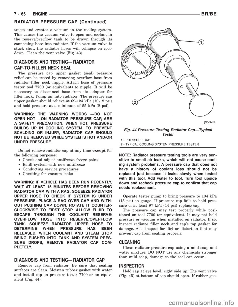
and install cap on pressure tester 7700 or an equiv-
alent (Fig. 44).NOTE: Radiator pressure testing tools are very sen-
sitive to small air leaks, which will not cause cool-
ing system problems. A pressure cap that does not
have a history of coolant loss should not be
replaced just because it leaks slowly when tested
with this tool. Add water to tool. Turn tool upside
down and recheck pressure cap to confirm that cap
needs replacement.
Operate tester pump to bring pressure to 104 kPa
(15 psi) on gauge. If pressure cap fails to hold pres-
sure of at least 97 kPa (14 psi) replace cap.
The pressure cap may test properly while posi-
tioned on tool 7700 (or equivalent). It may not hold
pressure or vacuum when installed on radiator. If so,
inspect radiator filler neck and cap's top gasket for
damage. Also inspect for dirt or distortion that may
prevent cap from sealing properly.
CLEANING
Clean radiator pressure cap using a mild soap and
water mixture. DO NOT use any chemicals stronger
than mild soap, damage to the seal can occur .
INSPECTION
Hold cap at eye level, right side up. The vent valve
(Fig. 45) at bottom of cap should open. If rubber gas-
Fig. 44 Pressure Testing Radiator CapÐTypical
Tester
1 - PRESSURE CAP
2 - TYPICAL COOLING SYSTEM PRESSURE TESTER
7 - 66 ENGINEBR/BE
RADIATOR PRESSURE CAP (Continued)
Page 414 of 2889
TRANSMISSION
TABLE OF CONTENTS
page page
TRANS COOLER - 3.9L/5.2L/5.9L
DESCRIPTION...........................79
OPERATION.............................79
STANDARD PROCEDURE..................79
FLUSHING COOLERS AND TUBES - WITH
RADIATOR IN-TANK TRANSMISSION OIL
COOLER..............................79
FLUSHING COOLER AND TUBES -
WITHOUT RADIATOR IN-TANK
TRANSMISSION OIL COOLER.............80
REMOVAL..............................81
DISASSEMBLY...........................81
ASSEMBLY.............................82
INSTALLATION...........................82
TRANS COOLER - 8.0L
DESCRIPTION...........................82
OPERATION.............................82
STANDARD PROCEDURE..................83
FLUSHING COOLERS AND TUBES - WITH
RADIATOR IN-TANK TRANSMISSION OIL
COOLER..............................83FLUSHING COOLER AND TUBES -
WITHOUT RADIATOR IN-TANK
TRANSMISSION OIL COOLER.............83
REMOVAL..............................84
INSTALLATION...........................85
TRANS COOLER - 5.9L DIESEL
DESCRIPTION...........................85
OPERATION.............................85
STANDARD PROCEDURE..................85
FLUSHING COOLERS AND TUBES - WITH
RADIATOR IN-TANK TRANSMISSION OIL
COOLER..............................85
FLUSHING COOLER AND TUBES -
WITHOUT RADIATOR IN-TANK
TRANSMISSION OIL COOLER.............86
REMOVAL..............................87
INSTALLATION...........................88
TRANS COOLER - 3.9L/5.2L/
5.9L
DESCRIPTION
An air-to-oil transmission oil cooler is standard on
all engine packages. the cooler is located between the
radiator and air conditioning condenser (Fig. 1).
OPERATION
The transmission oil is routed through the cooler
where heat is removed from the transmission oil
before returning to the transmission. The cooler has
an internal thermostat that controls fluid flow
through the cooler. When the transmission fluid is
cold ( less than operating temperature) the fluid is
routed through the cooler bypass. when the transmis-
sion fluid reaches operating temperatures and above,the thermostat closes off the bypass allowing fluid
flow through the cooler. The thermostat MUST be
removed from the cooler before the cooler can be
flushed. The thermostat is serviceable.
STANDARD PROCEDURE - FLUSHING
COOLERS AND TUBES - WITH RADIATOR
IN-TANK TRANSMISSION OIL COOLER
When a transmission failure has contaminated the
fluid, the oil cooler(s) must be flushed. The torque
converter must also be replaced. This will insure that
metal particles or sludged oil are not later trans-
ferred back into the reconditioned (or replaced) trans-
mission.
The only recommended procedure for flushing cool-
ers and lines is to use Tool 6906-B Cooler Flusher.
BR/BETRANSMISSION 7 - 79
Page 425 of 2889
Refer to Electrical, Restraints for more information
on the clockspring. Refer to Electrical, Body Control/
Central Control Module for more information on the
Central Timer Module. Refer to the appropriate wir-
ing information. The wiring information includes wir-
ing diagrams, proper wire and connector repair
procedures, details of wire harness routing and
retention, connector pin-out information and location
views for the various wire harness connectors, splices
and grounds. Following are general descriptions of
the remaining major components in the standard and
optional factory-installed audio systems.
OPERATION
See the owner's manual in the vehicle glove box for
more information on the features, use and operation
of each of the available audio systems.
CENTRAL TIMER MODULE
The high-line or premium Central Timer Module
(CTM) can also control some features of the audio
system when the vehicle is equipped with the
optional RAZ radio receiver and remote radio
switches. A high-line CTM is used on high-line ver-
sions of this vehicle. A premium CTM is used on
vehicles equipped with the optional heated seats. The
CTM combines the functions of a chime/buzzer mod-
ule, an intermittent wipe module, an illuminated
entry module, a remote keyless entry module, and a
vehicle theft security system module in a single unit.
The high-line or premium CTM also controls and
integrates many of the additional electronic functions
and features included on models with this option.The RAZ radio receiver with a remote radio switch
option is one of the features that the CTM controls.
The CTM is programmed to send switch status mes-
sages over the Chrysler Collision Detection (CCD)
data bus to control the volume, seek, and pre-set sta-
tion advance functions of the RAZ radio receiver. The
CTM monitors the status of the remote radio
switches located on the steering wheel through a
hard wired circuit. The CTM then sends the proper
switch status messages to the radio receiver. The
electronic circuitry within the radio receiver responds
to the switch status messages it receives by adjusting
the radio settings as requested.
Refer to Electrical, Body Control/Central Timer
Module for more information on the high-line CTM.
Refer to Remote Radio Switch in Description and
Operation for more information on this component.
In addition, radio receivers connected to the CCD
data bus have several audio system functions that
can be diagnosed using a DRBIIItscan tool. Refer to
the proper Diagnostic Procedures manual for more
information on DRBIIIttesting of the audio systems.
DIAGNOSIS AND TESTING - AUDIO
WARNING: ON VEHICLES EQUIPPED WITH AIR-
BAGS, REFER TO ELECTRICAL, RESTRAINTS
BEFORE ATTEMPTING ANY STEERING WHEEL,
STEERING COLUMN, OR INSTRUMENT PANEL
COMPONENT DIAGNOSIS OR SERVICE. FAILURE
TO TAKE THE PROPER PRECAUTIONS COULD
RESULT IN ACCIDENTAL AIRBAG DEPLOYMENT
AND POSSIBLE PERSONAL INJURY.
8A - 2 AUDIOBR/BE
AUDIO (Continued)