2001 CHRYSLER VOYAGER engine
[x] Cancel search: enginePage 2766 of 4284
DESCRIPTION TORQUE*
STRIP-OUT REPAIR SCREWS ONLY
MAP Sensor Repair
Screw4 N´m (35 in. lbs.)
Power Steering Reservoir
Repair Screw9 N´m (80 in. lbs.)
EGR Tube Attaching
Repair Screw9 N´m (80 in. lbs.)
Throttle Cable Bracket
Repair Screw9 N´m (80 in. lbs.)
*Install Slowly Using Hand Tools Only
STANDARD PROCEDURE - INTAKE MANIFOLD
VACUUM PORT REPAIR
The composite intake manifold vacuum ports can
be repaired. Although, if the manifold plenum cham-ber is damaged or cracked, the manifold must be
replaced.
To repair a broken or damaged vacuum nipple
(port) on the composite intake manifold, perform the
following procedure:
PARTS REQUIRED TOOLS REQUIRED
Brass Nipple ± 1/49O.D.
x 1/89pipe thread
(LDP/Speed Control Port)Pipe Tap ± 1/49-18NPT
& 1/89-18NPT
Brass Nipple ± 1/29O.D.
x 1/49pipe thread (Brake
Booster Port)Drill Bit ± 7/169& 11/329
File/Sand Paper
NOTE: While performing this procedure, avoid get-
ting the manifold material residue into the plenum
chamber.
(1) File or sand the remaining port back until a
flat surface is obtained (plane normal to nipple (port)
axis).
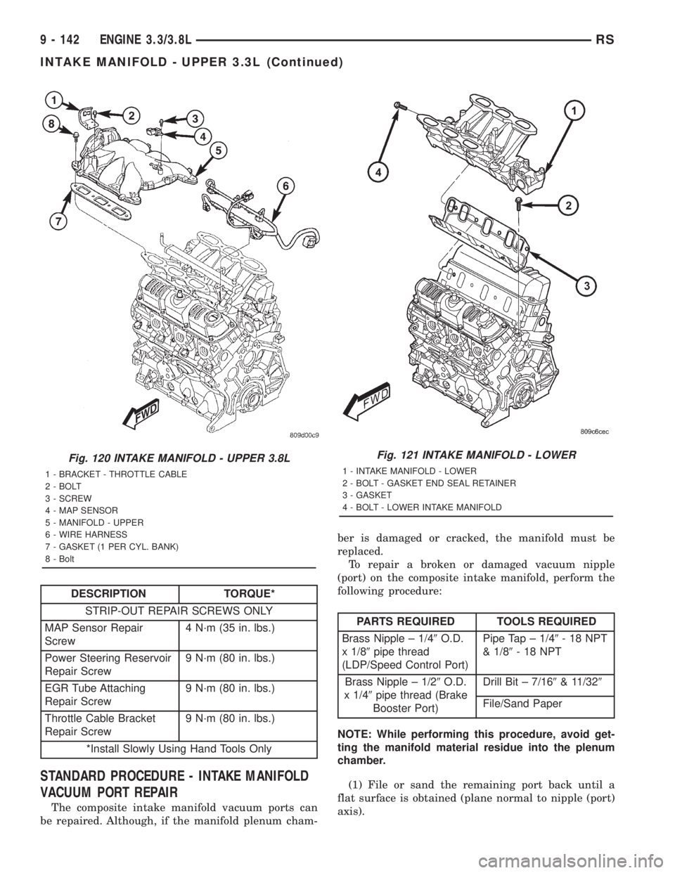
Fig. 120 INTAKE MANIFOLD - UPPER 3.8L
1 - BRACKET - THROTTLE CABLE
2 - BOLT
3 - SCREW
4 - MAP SENSOR
5 - MANIFOLD - UPPER
6 - WIRE HARNESS
7 - GASKET (1 PER CYL. BANK)
8 - Bolt
Fig. 121 INTAKE MANIFOLD - LOWER
1 - INTAKE MANIFOLD - LOWER
2 - BOLT - GASKET END SEAL RETAINER
3 - GASKET
4 - BOLT - LOWER INTAKE MANIFOLD
9 - 142 ENGINE 3.3/3.8LRS
INTAKE MANIFOLD - UPPER 3.3L (Continued)
Page 2767 of 4284
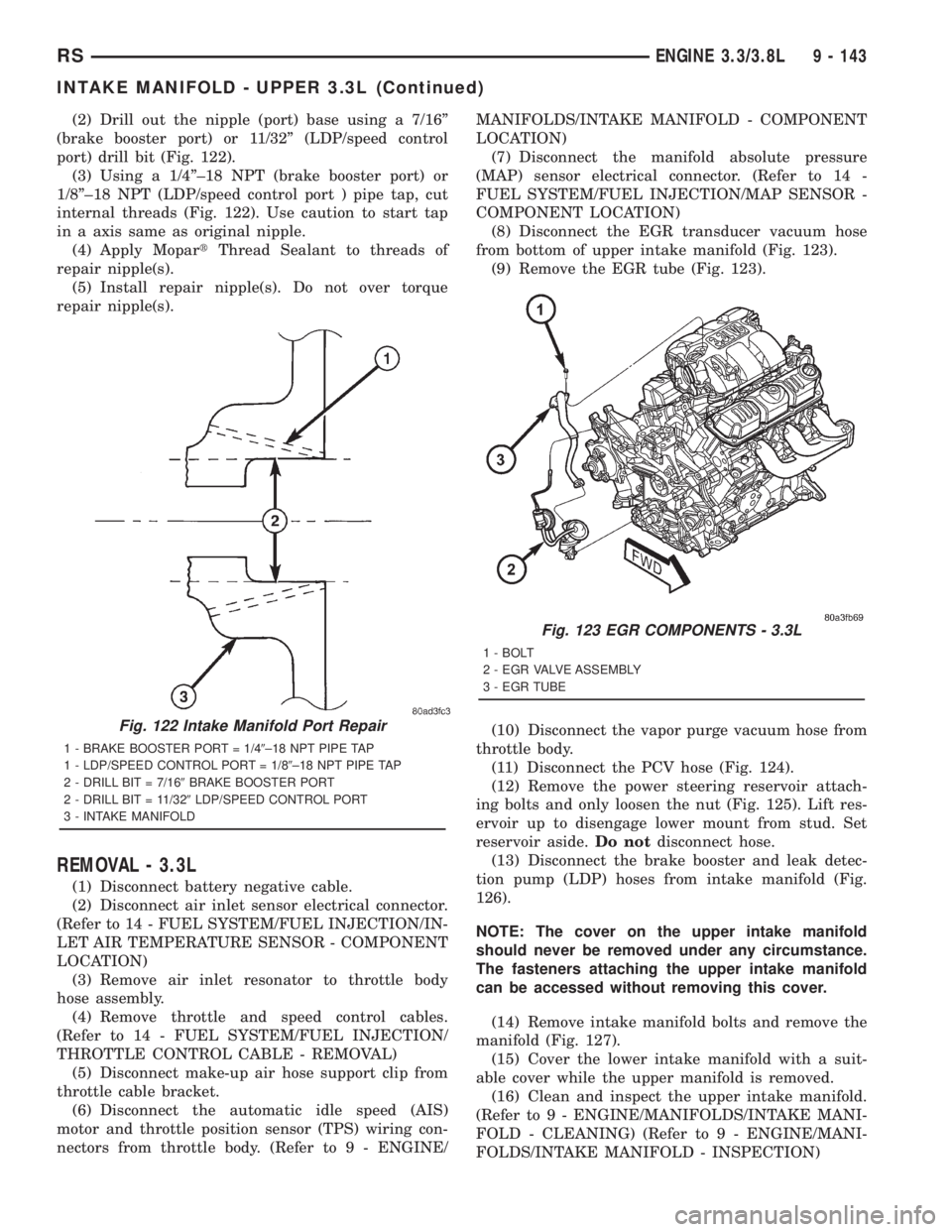
(2) Drill out the nipple (port) base using a 7/16º
(brake booster port) or 11/32º (LDP/speed control
port) drill bit (Fig. 122).
(3) Using a 1/4º±18 NPT (brake booster port) or
1/8º±18 NPT (LDP/speed control port ) pipe tap, cut
internal threads (Fig. 122). Use caution to start tap
in a axis same as original nipple.
(4) Apply MopartThread Sealant to threads of
repair nipple(s).
(5) Install repair nipple(s). Do not over torque
repair nipple(s).
REMOVAL - 3.3L
(1) Disconnect battery negative cable.
(2) Disconnect air inlet sensor electrical connector.
(Refer to 14 - FUEL SYSTEM/FUEL INJECTION/IN-
LET AIR TEMPERATURE SENSOR - COMPONENT
LOCATION)
(3) Remove air inlet resonator to throttle body
hose assembly.
(4) Remove throttle and speed control cables.
(Refer to 14 - FUEL SYSTEM/FUEL INJECTION/
THROTTLE CONTROL CABLE - REMOVAL)
(5) Disconnect make-up air hose support clip from
throttle cable bracket.
(6) Disconnect the automatic idle speed (AIS)
motor and throttle position sensor (TPS) wiring con-
nectors from throttle body. (Refer to 9 - ENGINE/MANIFOLDS/INTAKE MANIFOLD - COMPONENT
LOCATION)
(7) Disconnect the manifold absolute pressure
(MAP) sensor electrical connector. (Refer to 14 -
FUEL SYSTEM/FUEL INJECTION/MAP SENSOR -
COMPONENT LOCATION)
(8) Disconnect the EGR transducer vacuum hose
from bottom of upper intake manifold (Fig. 123).
(9) Remove the EGR tube (Fig. 123).
(10) Disconnect the vapor purge vacuum hose from
throttle body.
(11) Disconnect the PCV hose (Fig. 124).
(12) Remove the power steering reservoir attach-
ing bolts and only loosen the nut (Fig. 125). Lift res-
ervoir up to disengage lower mount from stud. Set
reservoir aside.Do notdisconnect hose.
(13) Disconnect the brake booster and leak detec-
tion pump (LDP) hoses from intake manifold (Fig.
126).
NOTE: The cover on the upper intake manifold
should never be removed under any circumstance.
The fasteners attaching the upper intake manifold
can be accessed without removing this cover.
(14) Remove intake manifold bolts and remove the
manifold (Fig. 127).
(15) Cover the lower intake manifold with a suit-
able cover while the upper manifold is removed.
(16) Clean and inspect the upper intake manifold.
(Refer to 9 - ENGINE/MANIFOLDS/INTAKE MANI-
FOLD - CLEANING) (Refer to 9 - ENGINE/MANI-
FOLDS/INTAKE MANIFOLD - INSPECTION)
Fig. 122 Intake Manifold Port Repair
1 - BRAKE BOOSTER PORT = 1/49±18 NPT PIPE TAP
1 - LDP/SPEED CONTROL PORT = 1/89±18 NPT PIPE TAP
2 - DRILL BIT = 7/169BRAKE BOOSTER PORT
2 - DRILL BIT = 11/329LDP/SPEED CONTROL PORT
3 - INTAKE MANIFOLD
Fig. 123 EGR COMPONENTS - 3.3L
1 - BOLT
2 - EGR VALVE ASSEMBLY
3 - EGR TUBE
RSENGINE 3.3/3.8L9 - 143
INTAKE MANIFOLD - UPPER 3.3L (Continued)
Page 2768 of 4284
CLEANING
(1) Discard gasket(s).
(2) Clean all sealing surfaces.
INSPECTION
Check manifold for:
²Damage and cracks.
²Mounting surface distortion by using a straight-
edge and thickness gauge.
INSTALLATION - 3.3L
(1) If the following components were removed from
manifold, install and tighten to specifications:
CAUTION: The special screws used for the compos-
ite manifold attached components must be installed
slowly using hand tools only. This requirement is to
prevent the melting of material that causes stripped
threads. If threads become stripped, an oversize
repair screw is available. For more information and
procedure (Refer to 9 - ENGINE/MANIFOLDS/IN-
TAKE MANIFOLD - STANDARD PROCEDURE).
²MAP sensor - 1.7 N´m (15 in. lbs.)
²Throttle cable bracket - 5.6 N´m (50 in. lbs.)
(2) Remove covering on lower intake manifold and
clean surfaces.
(3) Inspect manifold gasket condition. Gaskets can
be re-used, if not damaged. To replace, remove gasket
from upper manifold (Fig. 127). Position new gasket
in seal channel and press lightly in-place. Repeat
procedure for each gasket position.
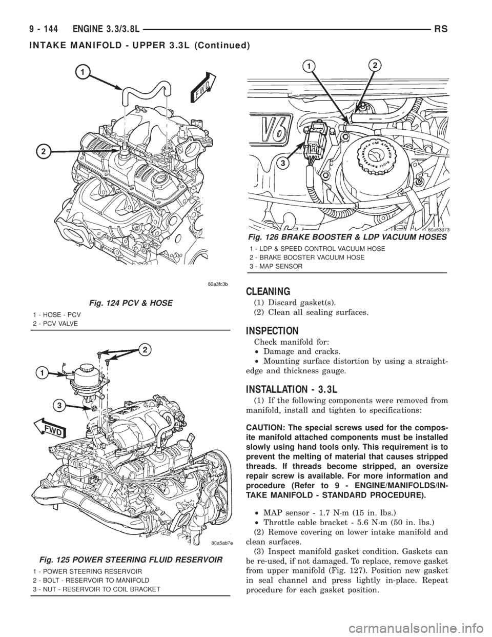
Fig. 124 PCV & HOSE
1 - HOSE - PCV
2 - P C V VA LV E
Fig. 125 POWER STEERING FLUID RESERVOIR
1 - POWER STEERING RESERVOIR
2 - BOLT - RESERVOIR TO MANIFOLD
3 - NUT - RESERVOIR TO COIL BRACKET
Fig. 126 BRAKE BOOSTER & LDP VACUUM HOSES
1 - LDP & SPEED CONTROL VACUUM HOSE
2 - BRAKE BOOSTER VACUUM HOSE
3 - MAP SENSOR
9 - 144 ENGINE 3.3/3.8LRS
INTAKE MANIFOLD - UPPER 3.3L (Continued)
Page 2769 of 4284
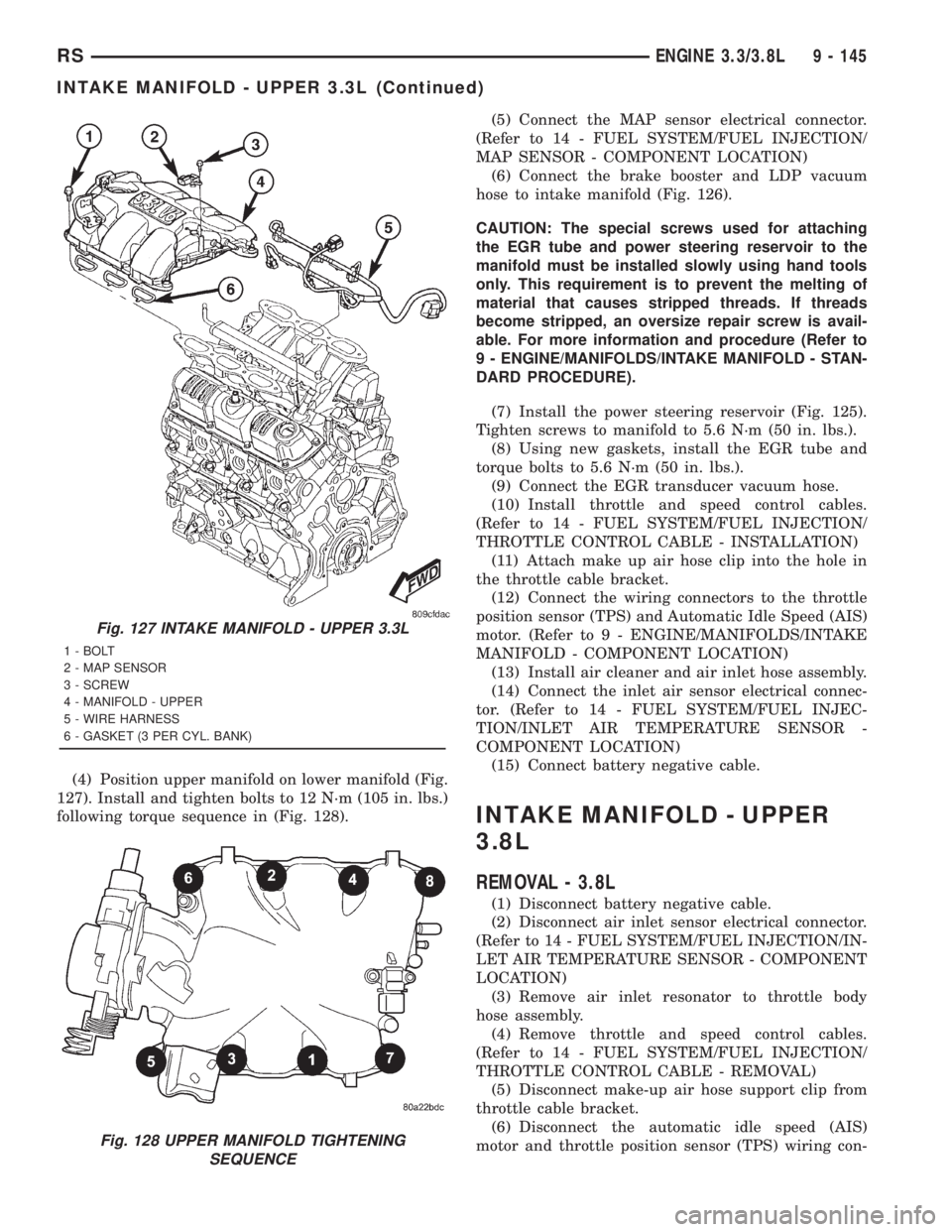
(4) Position upper manifold on lower manifold (Fig.
127). Install and tighten bolts to 12 N´m (105 in. lbs.)
following torque sequence in (Fig. 128).(5) Connect the MAP sensor electrical connector.
(Refer to 14 - FUEL SYSTEM/FUEL INJECTION/
MAP SENSOR - COMPONENT LOCATION)
(6) Connect the brake booster and LDP vacuum
hose to intake manifold (Fig. 126).
CAUTION: The special screws used for attaching
the EGR tube and power steering reservoir to the
manifold must be installed slowly using hand tools
only. This requirement is to prevent the melting of
material that causes stripped threads. If threads
become stripped, an oversize repair screw is avail-
able. For more information and procedure (Refer to
9 - ENGINE/MANIFOLDS/INTAKE MANIFOLD - STAN-
DARD PROCEDURE).
(7) Install the power steering reservoir (Fig. 125).
Tighten screws to manifold to 5.6 N´m (50 in. lbs.).
(8) Using new gaskets, install the EGR tube and
torque bolts to 5.6 N´m (50 in. lbs.).
(9) Connect the EGR transducer vacuum hose.
(10) Install throttle and speed control cables.
(Refer to 14 - FUEL SYSTEM/FUEL INJECTION/
THROTTLE CONTROL CABLE - INSTALLATION)
(11) Attach make up air hose clip into the hole in
the throttle cable bracket.
(12) Connect the wiring connectors to the throttle
position sensor (TPS) and Automatic Idle Speed (AIS)
motor. (Refer to 9 - ENGINE/MANIFOLDS/INTAKE
MANIFOLD - COMPONENT LOCATION)
(13) Install air cleaner and air inlet hose assembly.
(14) Connect the inlet air sensor electrical connec-
tor. (Refer to 14 - FUEL SYSTEM/FUEL INJEC-
TION/INLET AIR TEMPERATURE SENSOR -
COMPONENT LOCATION)
(15) Connect battery negative cable.
INTAKE MANIFOLD - UPPER
3.8L
REMOVAL - 3.8L
(1) Disconnect battery negative cable.
(2) Disconnect air inlet sensor electrical connector.
(Refer to 14 - FUEL SYSTEM/FUEL INJECTION/IN-
LET AIR TEMPERATURE SENSOR - COMPONENT
LOCATION)
(3) Remove air inlet resonator to throttle body
hose assembly.
(4) Remove throttle and speed control cables.
(Refer to 14 - FUEL SYSTEM/FUEL INJECTION/
THROTTLE CONTROL CABLE - REMOVAL)
(5) Disconnect make-up air hose support clip from
throttle cable bracket.
(6) Disconnect the automatic idle speed (AIS)
motor and throttle position sensor (TPS) wiring con-
Fig. 127 INTAKE MANIFOLD - UPPER 3.3L
1 - BOLT
2 - MAP SENSOR
3 - SCREW
4 - MANIFOLD - UPPER
5 - WIRE HARNESS
6 - GASKET (3 PER CYL. BANK)
Fig. 128 UPPER MANIFOLD TIGHTENING
SEQUENCE
RSENGINE 3.3/3.8L9 - 145
INTAKE MANIFOLD - UPPER 3.3L (Continued)
Page 2770 of 4284
nectors from throttle body. (Refer to 9 - ENGINE/
MANIFOLDS/INTAKE MANIFOLD - COMPONENT
LOCATION)
(7) Disconnect the manifold absolute pressure
(MAP) sensor electrical connector. (Refer to 14 -
FUEL SYSTEM/FUEL INJECTION/MAP SENSOR -
COMPONENT LOCATION)
(8) Disconnect the EGR transducer vacuum hose
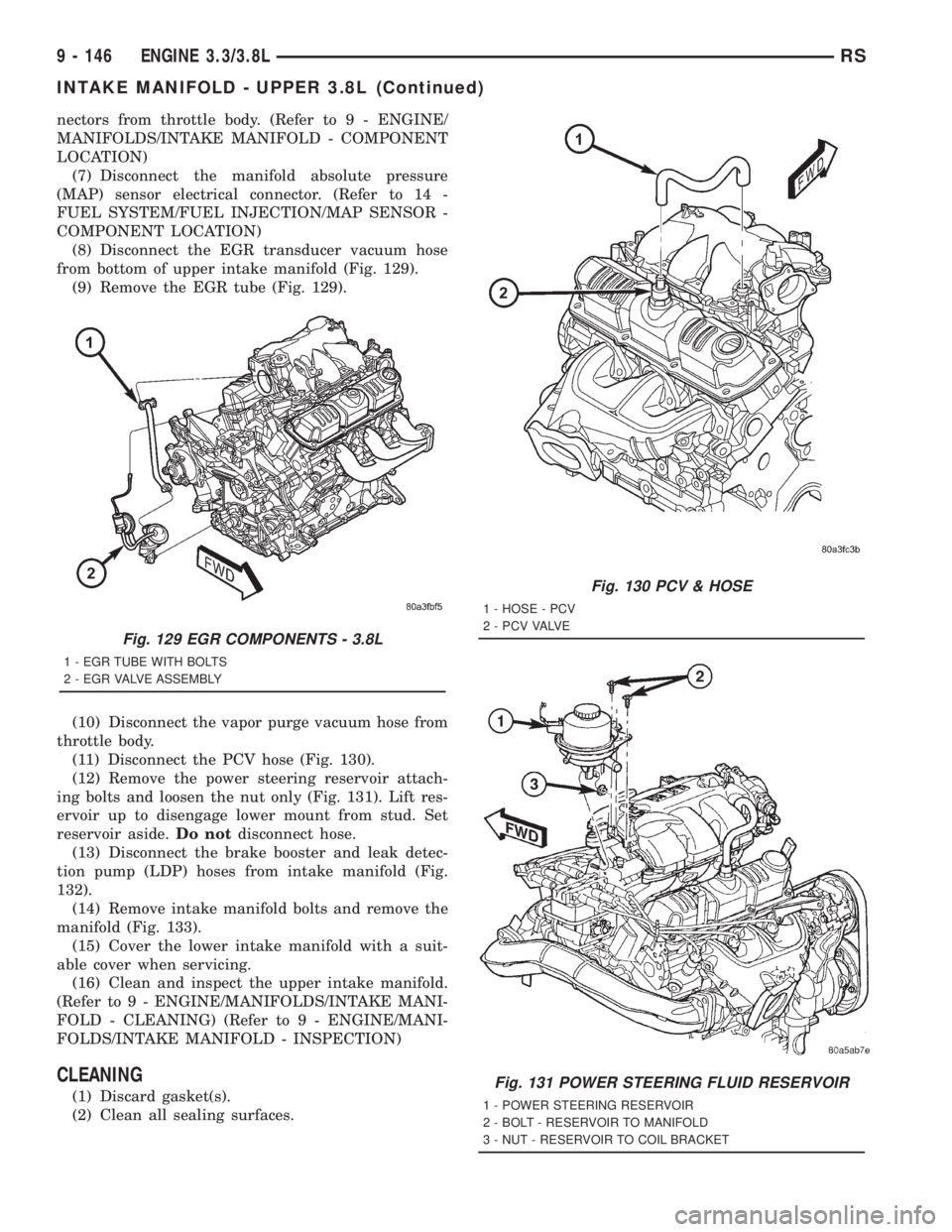
from bottom of upper intake manifold (Fig. 129).
(9) Remove the EGR tube (Fig. 129).
(10) Disconnect the vapor purge vacuum hose from
throttle body.
(11) Disconnect the PCV hose (Fig. 130).
(12) Remove the power steering reservoir attach-
ing bolts and loosen the nut only (Fig. 131). Lift res-
ervoir up to disengage lower mount from stud. Set
reservoir aside.Do notdisconnect hose.
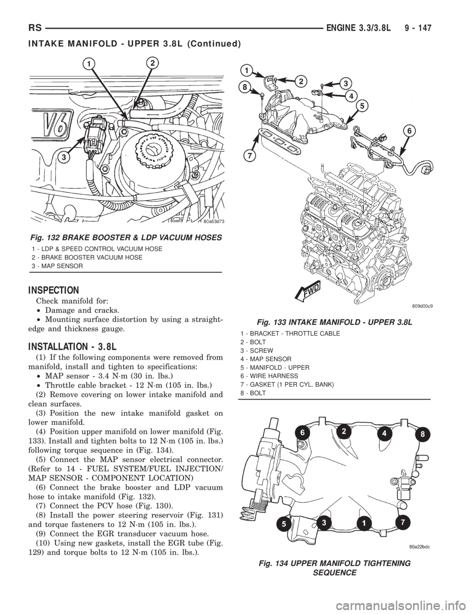
(13) Disconnect the brake booster and leak detec-
tion pump (LDP) hoses from intake manifold (Fig.
132).
(14) Remove intake manifold bolts and remove the
manifold (Fig. 133).
(15) Cover the lower intake manifold with a suit-
able cover when servicing.
(16) Clean and inspect the upper intake manifold.
(Refer to 9 - ENGINE/MANIFOLDS/INTAKE MANI-
FOLD - CLEANING) (Refer to 9 - ENGINE/MANI-
FOLDS/INTAKE MANIFOLD - INSPECTION)
CLEANING
(1) Discard gasket(s).
(2) Clean all sealing surfaces.
Fig. 129 EGR COMPONENTS - 3.8L
1 - EGR TUBE WITH BOLTS
2 - EGR VALVE ASSEMBLY
Fig. 130 PCV & HOSE
1 - HOSE - PCV
2 - P C V VA LV E
Fig. 131 POWER STEERING FLUID RESERVOIR
1 - POWER STEERING RESERVOIR
2 - BOLT - RESERVOIR TO MANIFOLD
3 - NUT - RESERVOIR TO COIL BRACKET
9 - 146 ENGINE 3.3/3.8LRS
INTAKE MANIFOLD - UPPER 3.8L (Continued)
Page 2771 of 4284
INSPECTION
Check manifold for:
²Damage and cracks.
²Mounting surface distortion by using a straight-
edge and thickness gauge.
INSTALLATION - 3.8L
(1) If the following components were removed from
manifold, install and tighten to specifications:
²MAP sensor - 3.4 N´m (30 in. lbs.)
²Throttle cable bracket - 12 N´m (105 in. lbs.)
(2) Remove covering on lower intake manifold and
clean surfaces.
(3) Position the new intake manifold gasket on
lower manifold.
(4) Position upper manifold on lower manifold (Fig.
133). Install and tighten bolts to 12 N´m (105 in. lbs.)
following torque sequence in (Fig. 134).
(5) Connect the MAP sensor electrical connector.
(Refer to 14 - FUEL SYSTEM/FUEL INJECTION/
MAP SENSOR - COMPONENT LOCATION)
(6) Connect the brake booster and LDP vacuum
hose to intake manifold (Fig. 132).
(7) Connect the PCV hose (Fig. 130).
(8) Install the power steering reservoir (Fig. 131)
and torque fasteners to 12 N´m (105 in. lbs.).
(9) Connect the EGR transducer vacuum hose.
(10) Using new gaskets, install the EGR tube (Fig.
129) and torque bolts to 12 N´m (105 in. lbs.).
Fig. 132 BRAKE BOOSTER & LDP VACUUM HOSES
1 - LDP & SPEED CONTROL VACUUM HOSE
2 - BRAKE BOOSTER VACUUM HOSE
3 - MAP SENSOR
Fig. 133 INTAKE MANIFOLD - UPPER 3.8L
1 - BRACKET - THROTTLE CABLE
2 - BOLT
3 - SCREW
4 - MAP SENSOR
5 - MANIFOLD - UPPER
6 - WIRE HARNESS
7 - GASKET (1 PER CYL. BANK)
8 - BOLT
Fig. 134 UPPER MANIFOLD TIGHTENING
SEQUENCE
RSENGINE 3.3/3.8L9 - 147
INTAKE MANIFOLD - UPPER 3.8L (Continued)
Page 2772 of 4284
(11) Install throttle and speed control cables.
(Refer to 14 - FUEL SYSTEM/FUEL INJECTION/
THROTTLE CONTROL CABLE - INSTALLATION)
(12) Attach make up air hose clip into the hole in
the throttle cable bracket.
(13) Connect the vapor purge vacuum hose to
throttle body.
(14) Connect the wiring connectors to the throttle
position sensor (TPS) and Automatic Idle Speed (AIS)
motor. (Refer to 9 - ENGINE/MANIFOLDS/INTAKE
MANIFOLD - COMPONENT LOCATION)
(15) Install air cleaner and air inlet hose assembly.
(16) Connect the inlet air sensor electrical connec-
tor. (Refer to 14 - FUEL SYSTEM/FUEL INJEC-
TION/INLET AIR TEMPERATURE SENSOR -
COMPONENT LOCATION)
(17) Connect battery negative cable.
INTAKE MANIFOLD - LOWER
REMOVAL
(1) Perform fuel system pressure release procedure
(before attempting any repairs).(Refer to 14 -
FUEL SYSTEM/FUEL DELIVERY - STANDARD
PROCEDURE)
(2) Drain the cooling system. (Refer to 7 - COOL-
ING - STANDARD PROCEDURE)
(3) Remove the upper intake manifold. (Refer to 9
- ENGINE/MANIFOLDS/INTAKE MANIFOLD -
REMOVAL)
(4) Remove the fuel line. (Refer to 14 - FUEL SYS-
TEM/FUEL DELIVERY/FUEL LINES - STANDARD
PROCEDURE) (Refer to 14 - FUEL SYSTEM/FUEL
DELIVERY/QUICK CONNECT FITTING - STAN-
DARD PROCEDURE)
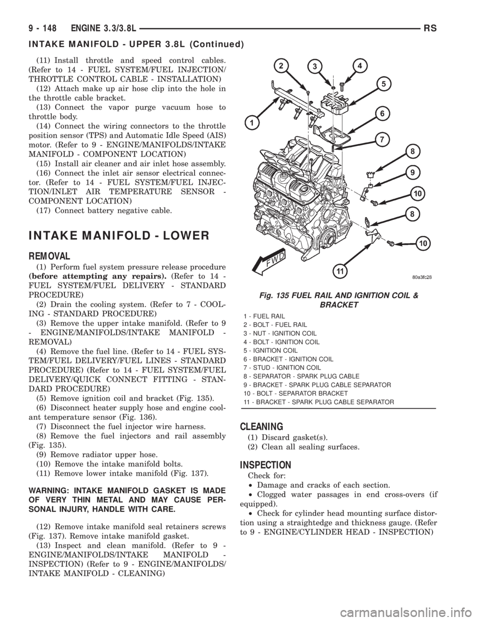
(5) Remove ignition coil and bracket (Fig. 135).
(6) Disconnect heater supply hose and engine cool-
ant temperature sensor (Fig. 136).
(7) Disconnect the fuel injector wire harness.
(8) Remove the fuel injectors and rail assembly
(Fig. 135).
(9) Remove radiator upper hose.
(10) Remove the intake manifold bolts.
(11) Remove lower intake manifold (Fig. 137).
WARNING: INTAKE MANIFOLD GASKET IS MADE
OF VERY THIN METAL AND MAY CAUSE PER-
SONAL INJURY, HANDLE WITH CARE.
(12) Remove intake manifold seal retainers screws
(Fig. 137). Remove intake manifold gasket.
(13) Inspect and clean manifold. (Refer to 9 -
ENGINE/MANIFOLDS/INTAKE MANIFOLD -
INSPECTION) (Refer to 9 - ENGINE/MANIFOLDS/
INTAKE MANIFOLD - CLEANING)
CLEANING
(1) Discard gasket(s).
(2) Clean all sealing surfaces.
INSPECTION
Check for:
²Damage and cracks of each section.
²Clogged water passages in end cross-overs (if
equipped).
²Check for cylinder head mounting surface distor-
tion using a straightedge and thickness gauge. (Refer
to 9 - ENGINE/CYLINDER HEAD - INSPECTION)
Fig. 135 FUEL RAIL AND IGNITION COIL &
BRACKET
1 - FUEL RAIL
2 - BOLT - FUEL RAIL
3 - NUT - IGNITION COIL
4 - BOLT - IGNITION COIL
5 - IGNITION COIL
6 - BRACKET - IGNITION COIL
7 - STUD - IGNITION COIL
8 - SEPARATOR - SPARK PLUG CABLE
9 - BRACKET - SPARK PLUG CABLE SEPARATOR
10 - BOLT - SEPARATOR BRACKET
11 - BRACKET - SPARK PLUG CABLE SEPARATOR
9 - 148 ENGINE 3.3/3.8LRS
INTAKE MANIFOLD - UPPER 3.8L (Continued)
Page 2773 of 4284
INSTALLATION
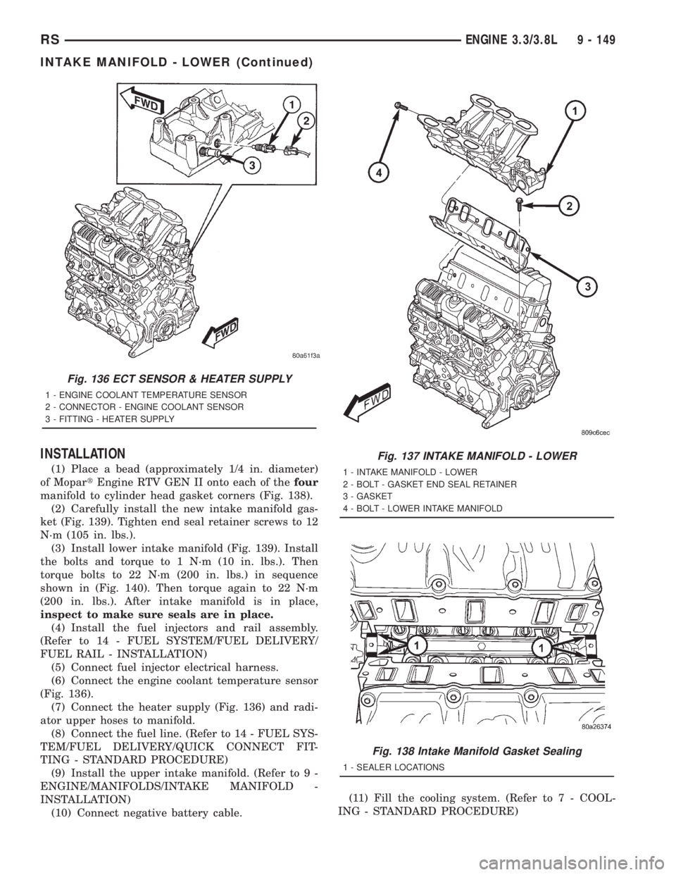
(1) Place a bead (approximately 1/4 in. diameter)
of MopartEngine RTV GEN II onto each of thefour
manifold to cylinder head gasket corners (Fig. 138).
(2) Carefully install the new intake manifold gas-
ket (Fig. 139). Tighten end seal retainer screws to 12
N´m (105 in. lbs.).
(3) Install lower intake manifold (Fig. 139). Install
the bolts and torque to 1 N´m (10 in. lbs.). Then
torque bolts to 22 N´m (200 in. lbs.) in sequence
shown in (Fig. 140). Then torque again to 22 N´m
(200 in. lbs.). After intake manifold is in place,
inspect to make sure seals are in place.
(4) Install the fuel injectors and rail assembly.
(Refer to 14 - FUEL SYSTEM/FUEL DELIVERY/
FUEL RAIL - INSTALLATION)
(5) Connect fuel injector electrical harness.
(6) Connect the engine coolant temperature sensor
(Fig. 136).
(7) Connect the heater supply (Fig. 136) and radi-
ator upper hoses to manifold.
(8) Connect the fuel line. (Refer to 14 - FUEL SYS-
TEM/FUEL DELIVERY/QUICK CONNECT FIT-
TING - STANDARD PROCEDURE)
(9) Install the upper intake manifold. (Refer to 9 -
ENGINE/MANIFOLDS/INTAKE MANIFOLD -
INSTALLATION)
(10) Connect negative battery cable.(11) Fill the cooling system. (Refer to 7 - COOL-
ING - STANDARD PROCEDURE)
Fig. 136 ECT SENSOR & HEATER SUPPLY
1 - ENGINE COOLANT TEMPERATURE SENSOR
2 - CONNECTOR - ENGINE COOLANT SENSOR
3 - FITTING - HEATER SUPPLY
Fig. 137 INTAKE MANIFOLD - LOWER
1 - INTAKE MANIFOLD - LOWER
2 - BOLT - GASKET END SEAL RETAINER
3 - GASKET
4 - BOLT - LOWER INTAKE MANIFOLD
Fig. 138 Intake Manifold Gasket Sealing
1 - SEALER LOCATIONS
RSENGINE 3.3/3.8L9 - 149
INTAKE MANIFOLD - LOWER (Continued)