2001 CHRYSLER VOYAGER engine
[x] Cancel search: enginePage 2734 of 4284
OPERATION
The crankshaft transfers force generated by com-
bustion within the cylinder to the flywheel or flex-
plate.
STANDARD PROCEDURE - CRANKSHAFT END
PLAY
(1) Mount a dial indicator to front of engine with
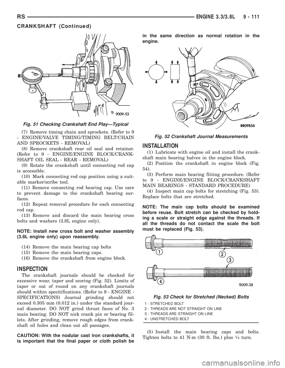
the locating probe on nose of crankshaft (Fig. 51).
(2) Move crankshaft all the way to the rear of its
travel.
(3) Zero the dial indicator.
(4) Move crankshaft all the way to the front and
read the dial indicator. (Refer to 9 - ENGINE -
SPECIFICATIONS) for end play specification.
REMOVAL
(1) Remove the engine assembly. (Refer to 9 -
ENGINE - REMOVAL)
(2) Separate transaxle from engine.
(3) Mount engine on an engine stand.
(4) Remove the oil filter.
(5) Remove the oil pan and oil pick-up tube. (Refer
to 9 - ENGINE/LUBRICATION/OIL PAN -
REMOVAL)
(6) Remove the timing chain cover. (Refer to 9 -
ENGINE/VALVE TIMING/TIMING BELT / CHAIN
COVER(S) - REMOVAL)
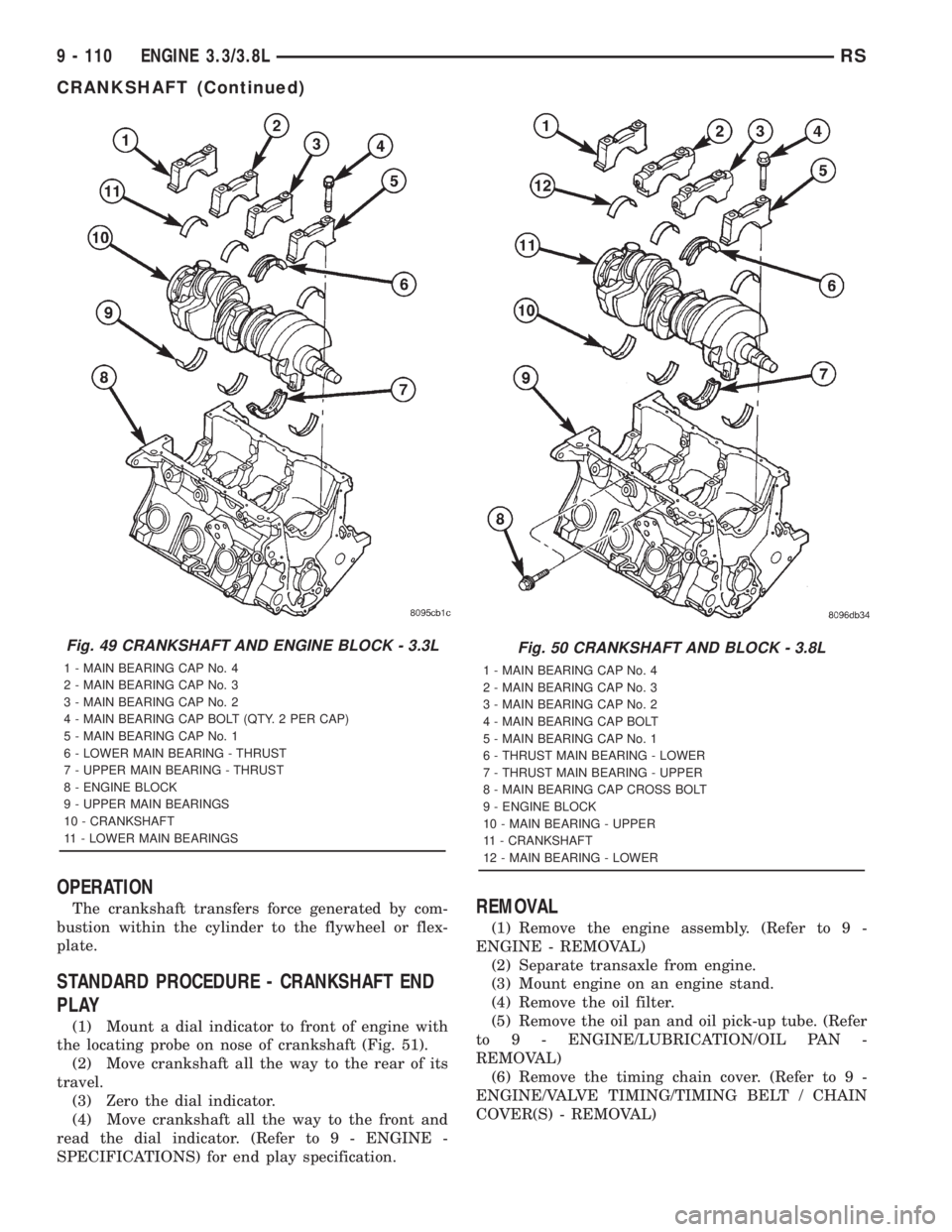
Fig. 49 CRANKSHAFT AND ENGINE BLOCK - 3.3L
1 - MAIN BEARING CAP No. 4
2 - MAIN BEARING CAP No. 3
3 - MAIN BEARING CAP No. 2
4 - MAIN BEARING CAP BOLT (QTY. 2 PER CAP)
5 - MAIN BEARING CAP No. 1
6 - LOWER MAIN BEARING - THRUST
7 - UPPER MAIN BEARING - THRUST
8 - ENGINE BLOCK
9 - UPPER MAIN BEARINGS
10 - CRANKSHAFT
11 - LOWER MAIN BEARINGS
Fig. 50 CRANKSHAFT AND BLOCK - 3.8L
1 - MAIN BEARING CAP No. 4
2 - MAIN BEARING CAP No. 3
3 - MAIN BEARING CAP No. 2
4 - MAIN BEARING CAP BOLT
5 - MAIN BEARING CAP No. 1
6 - THRUST MAIN BEARING - LOWER
7 - THRUST MAIN BEARING - UPPER
8 - MAIN BEARING CAP CROSS BOLT
9 - ENGINE BLOCK
10 - MAIN BEARING - UPPER
11 - CRANKSHAFT
12 - MAIN BEARING - LOWER
9 - 110 ENGINE 3.3/3.8LRS
CRANKSHAFT (Continued)
Page 2735 of 4284
(7) Remove timing chain and sprockets. (Refer to 9
- ENGINE/VALVE TIMING/TIMING BELT/CHAIN
AND SPROCKETS - REMOVAL)
(8) Remove crankshaft rear oil seal and retainer.
(Refer to 9 - ENGINE/ENGINE BLOCK/CRANK-
SHAFT OIL SEAL - REAR - REMOVAL)
(9) Rotate the crankshaft until connecting rod cap
is accessible.
(10) Mark connecting rod cap position using a suit-
able marker/scribe tool.
(11) Remove connecting rod bearing cap. Use care
to prevent damage to the crankshaft bearing sur-
faces.
(12) Repeat removal procedure for each connecting
rod cap.
(13) Remove and discard the main bearing cross
bolts and washers (3.8L engine only).
NOTE: Install new cross bolt and washer assembly
(3.8L engine only) upon reassembly.
(14) Remove the main bearing cap bolts
(15) Remove the main bearing caps.
(16) Remove the crankshaft from engine block.
INSPECTION
The crankshaft journals should be checked for
excessive wear, taper and scoring (Fig. 52). Limits of
taper or out of round on any crankshaft journals
should within specitifications. (Refer to 9 - ENGINE -
SPECIFICATIONS) Journal grinding should not
exceed 0.305 mm (0.012 in.) under the standard jour-
nal diameter. DO NOT grind thrust faces of No. 3
main bearing. DO NOT nick crank pin or bearing fil-
lets. After grinding, remove rough edges from crank-
shaft oil holes and clean out all passages.
CAUTION: With the nodular cast iron crankshafts, it
is important that the final paper or cloth polish bein the same direction as normal rotation in the
engine.
INSTALLATION
(1) Lubricate with engine oil and install the crank-
shaft main bearing halves in the engine block.
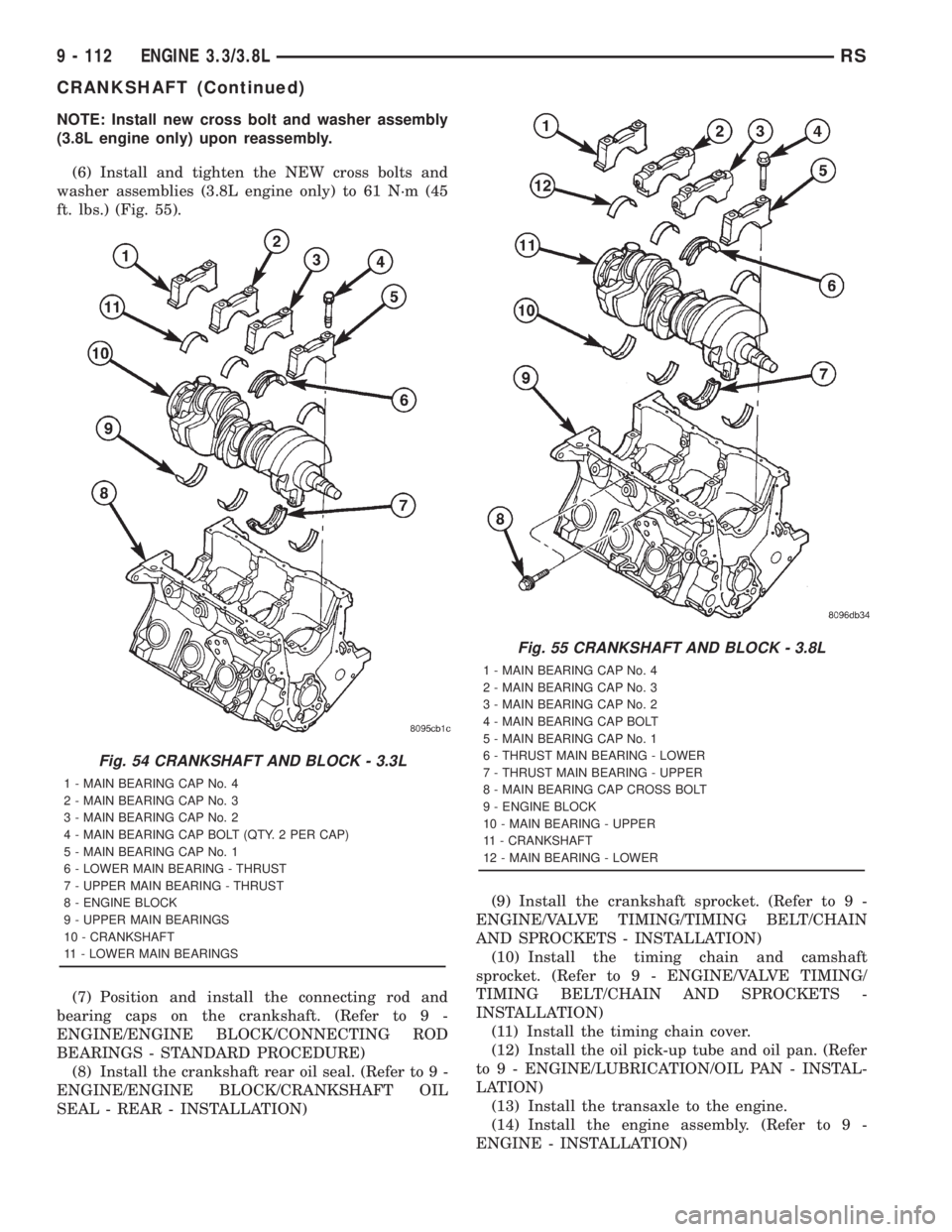
(2) Position the crankshaft in engine block (Fig.
54).
(3) Perform main bearing fitting procedure. (Refer
to 9 - ENGINE/ENGINE BLOCK/CRANKSHAFT
MAIN BEARINGS - STANDARD PROCEDURE)
(4) Inspect main cap bolts for stretching (Fig. 53).
Replace bolts that are stretched.
NOTE: The main cap bolts should be examined
before reuse. Bolt stretch can be checked by hold-
ing a scale or straight edge against the threads. If
all the threads do not contact the scale the bolt
must be replaced (Fig. 53).
(5) Install the main bearing caps and bolts.
Tighten bolts to 41 N´m (30 ft. lbs.) plus
1¤4turn.
Fig. 51 Checking Crankshaft End PlayÐTypical
Fig. 52 Crankshaft Journal Measurements
Fig. 53 Check for Stretched (Necked) Bolts
1 - STRETCHED BOLT
2 - THREADS ARE NOT STRAIGHT ON LINE
3 - THREADS ARE STRAIGHT ON LINE
4 - UNSTRETCHED BOLT
RSENGINE 3.3/3.8L9 - 111
CRANKSHAFT (Continued)
Page 2736 of 4284
NOTE: Install new cross bolt and washer assembly
(3.8L engine only) upon reassembly.
(6) Install and tighten the NEW cross bolts and
washer assemblies (3.8L engine only) to 61 N´m (45
ft. lbs.) (Fig. 55).
(7) Position and install the connecting rod and
bearing caps on the crankshaft. (Refer to 9 -
ENGINE/ENGINE BLOCK/CONNECTING ROD
BEARINGS - STANDARD PROCEDURE)
(8) Install the crankshaft rear oil seal. (Refer to 9 -
ENGINE/ENGINE BLOCK/CRANKSHAFT OIL
SEAL - REAR - INSTALLATION)(9) Install the crankshaft sprocket. (Refer to 9 -
ENGINE/VALVE TIMING/TIMING BELT/CHAIN
AND SPROCKETS - INSTALLATION)
(10) Install the timing chain and camshaft
sprocket. (Refer to 9 - ENGINE/VALVE TIMING/
TIMING BELT/CHAIN AND SPROCKETS -
INSTALLATION)
(11) Install the timing chain cover.
(12) Install the oil pick-up tube and oil pan. (Refer
to 9 - ENGINE/LUBRICATION/OIL PAN - INSTAL-
LATION)
(13) Install the transaxle to the engine.
(14) Install the engine assembly. (Refer to 9 -
ENGINE - INSTALLATION)
Fig. 54 CRANKSHAFT AND BLOCK - 3.3L
1 - MAIN BEARING CAP No. 4
2 - MAIN BEARING CAP No. 3
3 - MAIN BEARING CAP No. 2
4 - MAIN BEARING CAP BOLT (QTY. 2 PER CAP)
5 - MAIN BEARING CAP No. 1
6 - LOWER MAIN BEARING - THRUST
7 - UPPER MAIN BEARING - THRUST
8 - ENGINE BLOCK
9 - UPPER MAIN BEARINGS
10 - CRANKSHAFT
11 - LOWER MAIN BEARINGS
Fig. 55 CRANKSHAFT AND BLOCK - 3.8L
1 - MAIN BEARING CAP No. 4
2 - MAIN BEARING CAP No. 3
3 - MAIN BEARING CAP No. 2
4 - MAIN BEARING CAP BOLT
5 - MAIN BEARING CAP No. 1
6 - THRUST MAIN BEARING - LOWER
7 - THRUST MAIN BEARING - UPPER
8 - MAIN BEARING CAP CROSS BOLT
9 - ENGINE BLOCK
10 - MAIN BEARING - UPPER
11 - CRANKSHAFT
12 - MAIN BEARING - LOWER
9 - 112 ENGINE 3.3/3.8LRS
CRANKSHAFT (Continued)
Page 2737 of 4284
CRANKSHAFT MAIN
BEARINGS
STANDARD PROCEDURE - MAIN BEARING
FITTING
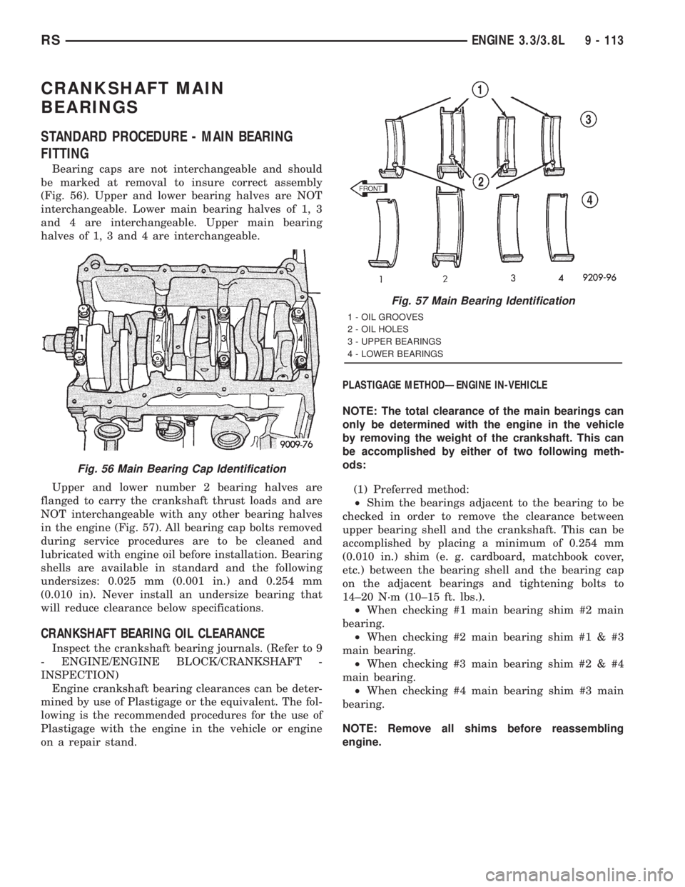
Bearing caps are not interchangeable and should
be marked at removal to insure correct assembly
(Fig. 56). Upper and lower bearing halves are NOT
interchangeable. Lower main bearing halves of 1, 3
and 4 are interchangeable. Upper main bearing
halves of 1, 3 and 4 are interchangeable.
Upper and lower number 2 bearing halves are
flanged to carry the crankshaft thrust loads and are
NOT interchangeable with any other bearing halves
in the engine (Fig. 57). All bearing cap bolts removed
during service procedures are to be cleaned and
lubricated with engine oil before installation. Bearing
shells are available in standard and the following
undersizes: 0.025 mm (0.001 in.) and 0.254 mm
(0.010 in). Never install an undersize bearing that
will reduce clearance below specifications.
CRANKSHAFT BEARING OIL CLEARANCE
Inspect the crankshaft bearing journals. (Refer to 9
- ENGINE/ENGINE BLOCK/CRANKSHAFT -
INSPECTION)
Engine crankshaft bearing clearances can be deter-
mined by use of Plastigage or the equivalent. The fol-
lowing is the recommended procedures for the use of
Plastigage with the engine in the vehicle or engine
on a repair stand.PLASTIGAGE METHODÐENGINE IN-VEHICLE
NOTE: The total clearance of the main bearings can
only be determined with the engine in the vehicle
by removing the weight of the crankshaft. This can
be accomplished by either of two following meth-
ods:
(1) Preferred method:
²Shim the bearings adjacent to the bearing to be
checked in order to remove the clearance between
upper bearing shell and the crankshaft. This can be
accomplished by placing a minimum of 0.254 mm
(0.010 in.) shim (e. g. cardboard, matchbook cover,
etc.) between the bearing shell and the bearing cap
on the adjacent bearings and tightening bolts to
14±20 N´m (10±15 ft. lbs.).
²When checking #1 main bearing shim #2 main
bearing.
²When checking #2 main bearing shim #1 & #3
main bearing.
²When checking #3 main bearing shim #2 & #4
main bearing.
²When checking #4 main bearing shim #3 main
bearing.
NOTE: Remove all shims before reassembling
engine.
Fig. 56 Main Bearing Cap Identification
Fig. 57 Main Bearing Identification
1 - OIL GROOVES
2 - OIL HOLES
3 - UPPER BEARINGS
4 - LOWER BEARINGS
RSENGINE 3.3/3.8L9 - 113
Page 2738 of 4284
(2) Alternative Method:
²Support the weight of the crankshaft with a jack
under the counterweight adjacent to the bearing
being checked.
(3) Remove oil film from surface to be checked.
Plastigage is soluble in oil.
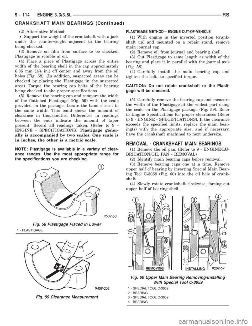
(4) Place a piece of Plastigage across the entire
width of the bearing shell in the cap approximately
6.35 mm (1/4 in.) off center and away from the oil
holes (Fig. 58). (In addition, suspected areas can be
checked by placing the Plastigage in the suspected
area). Torque the bearing cap bolts of the bearing
being checked to the proper specifications.
(5) Remove the bearing cap and compare the width
of the flattened Plastigage (Fig. 59) with the scale
provided on the package. Locate the band closest to
the same width. This band shows the amount of
clearance in thousandths. Differences in readings
between the ends indicate the amount of taper
present. Record all readings taken. (Refer to 9 -
ENGINE - SPECIFICATIONS)Plastigage gener-
ally is accompanied by two scales. One scale is
in inches, the other is a metric scale.
NOTE: Plastigage is available in a variety of clear-
ance ranges. Use the most appropriate range for
the specifications you are checking.PLASTIGAGE METHODÐENGINE OUT-OF-VEHICLE
(1) With engine in the inverted position (crank-
shaft up) and mounted on a repair stand, remove
main journal cap.
(2) Remove oil from journal and bearing shell.
(3) Cut Plastigage to same length as width of the
bearing and place it in parallel with the journal axis
(Fig. 58).
(4) Carefully install the main bearing cap and
tighten the bolts to specified torque.
CAUTION: Do not rotate crankshaft or the Plasti-
gage will be smeared.
(5) Carefully remove the bearing cap and measure
the width of the Plastigage at the widest part using
the scale on the Plastigage package (Fig. 59). Refer
to Engine Specifications for proper clearances (Refer
to 9 - ENGINE - SPECIFICATIONS). If the clearance
exceeds the specified limits, replace the main bear-
ing(s) with the appropriate size, and if necessary,
have the crankshaft machined to next undersize.
REMOVAL - CRANKSHAFT MAIN BEARINGS
(1) Remove the oil pan. (Refer to 9 - ENGINE/LU-
BRICATION/OIL PAN - REMOVAL)
(2) Identify main bearing caps before removal.
(3) Remove bearing caps one at a time. Remove
upper half of bearing by inserting Special Main Bear-
ing Tool C-3059 (Fig. 60) into the oil hole of crank-
shaft.
(4) Slowly rotate crankshaft clockwise, forcing out
upper half of bearing shell.
Fig. 58 Plastigage Placed in Lower
1 - PLASTIGAGE
Fig. 59 Clearance Measurement
Fig. 60 Upper Main Bearing Removing/Installing
With Special Tool C-3059
1 - SPECIAL TOOL C-3059
2 - BEARING
3 - SPECIAL TOOL C-3059
4 - BEARING
9 - 114 ENGINE 3.3/3.8LRS
CRANKSHAFT MAIN BEARINGS (Continued)
Page 2739 of 4284
INSTALLATION - CRANKSHAFT MAIN
BEARINGS
NOTE: One main bearing should be selectively fit-
ted while all other main bearing caps are properly
tightened.
(1) For main bearing fitting procedure, (Refer to 9
- ENGINE/ENGINE BLOCK/CRANKSHAFT MAIN
BEARINGS - STANDARD PROCEDURE)
(2) Start bearing in place, and insert Main Bearing
Tool C-3059 into oil hole of crankshaft (Fig. 60).
(3) Slowly rotate crankshaft counterclockwise slid-
ing the bearing into position. Remove Special Main
Bearing Tool C-3059.
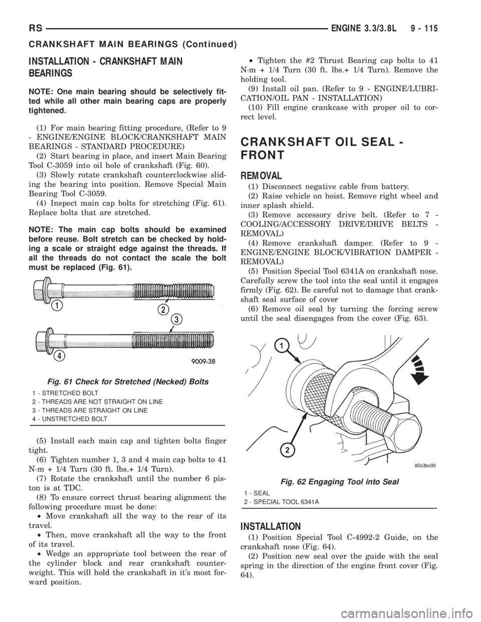
(4) Inspect main cap bolts for stretching (Fig. 61).
Replace bolts that are stretched.
NOTE: The main cap bolts should be examined
before reuse. Bolt stretch can be checked by hold-
ing a scale or straight edge against the threads. If
all the threads do not contact the scale the bolt
must be replaced (Fig. 61).
(5) Install each main cap and tighten bolts finger
tight.
(6) Tighten number 1, 3 and 4 main cap bolts to 41
N´m + 1/4 Turn (30 ft. lbs.+ 1/4 Turn).
(7) Rotate the crankshaft until the number 6 pis-
ton is at TDC.
(8) To ensure correct thrust bearing alignment the
following procedure must be done:
²Move crankshaft all the way to the rear of its
travel.
²Then, move crankshaft all the way to the front
of its travel.
²Wedge an appropriate tool between the rear of
the cylinder block and rear crankshaft counter-
weight. This will hold the crankshaft in it's most for-
ward position.²Tighten the #2 Thrust Bearing cap bolts to 41
N´m + 1/4 Turn (30 ft. lbs.+ 1/4 Turn). Remove the
holding tool.
(9) Install oil pan. (Refer to 9 - ENGINE/LUBRI-
CATION/OIL PAN - INSTALLATION)
(10) Fill engine crankcase with proper oil to cor-
rect level.
CRANKSHAFT OIL SEAL -
FRONT
REMOVAL
(1) Disconnect negative cable from battery.
(2) Raise vehicle on hoist. Remove right wheel and
inner splash shield.
(3) Remove accessory drive belt. (Refer to 7 -
COOLING/ACCESSORY DRIVE/DRIVE BELTS -
REMOVAL)
(4) Remove crankshaft damper. (Refer to 9 -
ENGINE/ENGINE BLOCK/VIBRATION DAMPER -
REMOVAL)
(5) Position Special Tool 6341A on crankshaft nose.
Carefully screw the tool into the seal until it engages
firmly (Fig. 62). Be careful not to damage that crank-
shaft seal surface of cover
(6) Remove oil seal by turning the forcing screw
until the seal disengages from the cover (Fig. 63).
INSTALLATION
(1) Position Special Tool C-4992-2 Guide, on the
crankshaft nose (Fig. 64).
(2) Position new seal over the guide with the seal
spring in the direction of the engine front cover (Fig.
64).
Fig. 61 Check for Stretched (Necked) Bolts
1 - STRETCHED BOLT
2 - THREADS ARE NOT STRAIGHT ON LINE
3 - THREADS ARE STRAIGHT ON LINE
4 - UNSTRETCHED BOLT
Fig. 62 Engaging Tool into Seal
1 - SEAL
2 - SPECIAL TOOL 6341A
RSENGINE 3.3/3.8L9 - 115
CRANKSHAFT MAIN BEARINGS (Continued)
Page 2740 of 4284
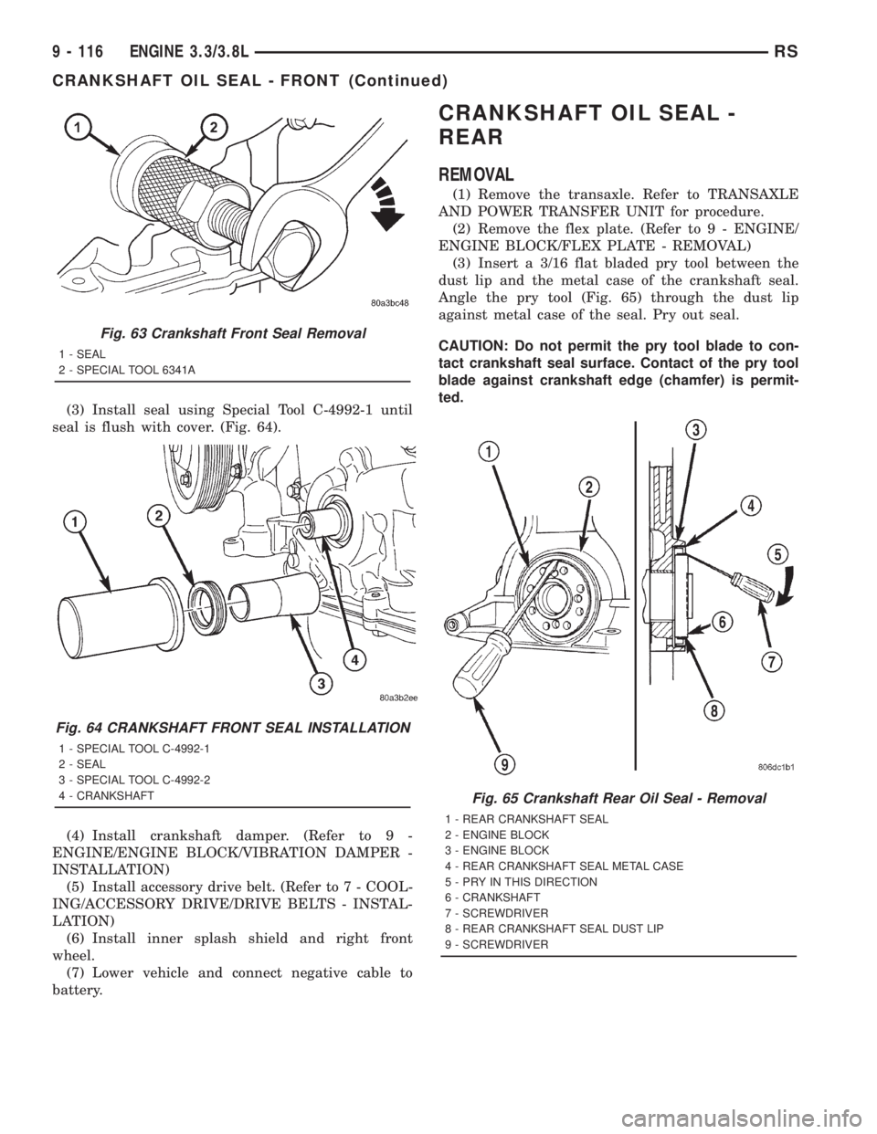
(3) Install seal using Special Tool C-4992-1 until
seal is flush with cover. (Fig. 64).
(4) Install crankshaft damper. (Refer to 9 -
ENGINE/ENGINE BLOCK/VIBRATION DAMPER -
INSTALLATION)
(5) Install accessory drive belt. (Refer to 7 - COOL-
ING/ACCESSORY DRIVE/DRIVE BELTS - INSTAL-
LATION)
(6) Install inner splash shield and right front
wheel.
(7) Lower vehicle and connect negative cable to
battery.
CRANKSHAFT OIL SEAL -
REAR
REMOVAL
(1) Remove the transaxle. Refer to TRANSAXLE
AND POWER TRANSFER UNIT for procedure.
(2) Remove the flex plate. (Refer to 9 - ENGINE/
ENGINE BLOCK/FLEX PLATE - REMOVAL)
(3) Insert a 3/16 flat bladed pry tool between the
dust lip and the metal case of the crankshaft seal.
Angle the pry tool (Fig. 65) through the dust lip
against metal case of the seal. Pry out seal.
CAUTION: Do not permit the pry tool blade to con-
tact crankshaft seal surface. Contact of the pry tool
blade against crankshaft edge (chamfer) is permit-
ted.
Fig. 63 Crankshaft Front Seal Removal
1 - SEAL
2 - SPECIAL TOOL 6341A
Fig. 64 CRANKSHAFT FRONT SEAL INSTALLATION
1 - SPECIAL TOOL C-4992-1
2 - SEAL
3 - SPECIAL TOOL C-4992-2
4 - CRANKSHAFT
Fig. 65 Crankshaft Rear Oil Seal - Removal
1 - REAR CRANKSHAFT SEAL
2 - ENGINE BLOCK
3 - ENGINE BLOCK
4 - REAR CRANKSHAFT SEAL METAL CASE
5 - PRY IN THIS DIRECTION
6 - CRANKSHAFT
7 - SCREWDRIVER
8 - REAR CRANKSHAFT SEAL DUST LIP
9 - SCREWDRIVER
9 - 116 ENGINE 3.3/3.8LRS
CRANKSHAFT OIL SEAL - FRONT (Continued)
Page 2741 of 4284
INSTALLATION
CAUTION: If burr or scratch is present on the
crankshaft edge (chamfer), cleanup with 400 grit
sand paper to prevent seal damage during installa-
tion of new seal.
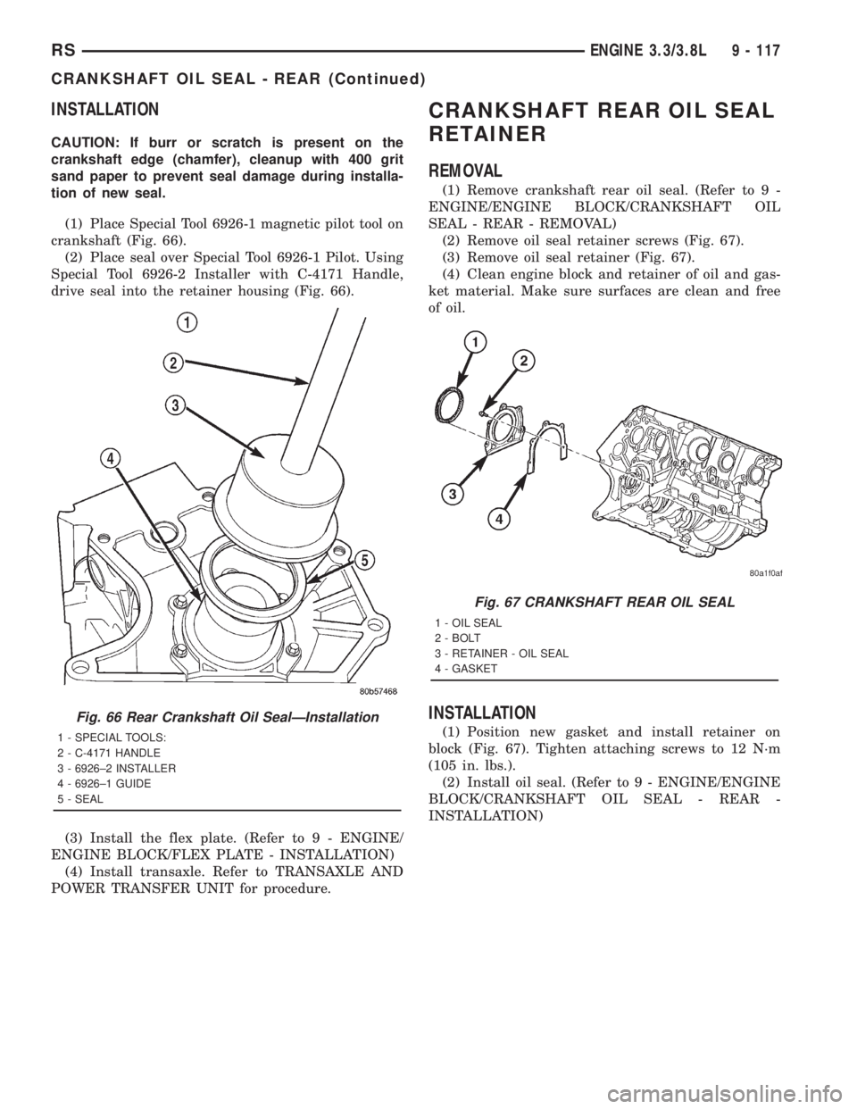
(1) Place Special Tool 6926-1 magnetic pilot tool on
crankshaft (Fig. 66).
(2) Place seal over Special Tool 6926-1 Pilot. Using
Special Tool 6926-2 Installer with C-4171 Handle,
drive seal into the retainer housing (Fig. 66).
(3) Install the flex plate. (Refer to 9 - ENGINE/
ENGINE BLOCK/FLEX PLATE - INSTALLATION)
(4) Install transaxle. Refer to TRANSAXLE AND
POWER TRANSFER UNIT for procedure.
CRANKSHAFT REAR OIL SEAL
RETAINER
REMOVAL
(1) Remove crankshaft rear oil seal. (Refer to 9 -
ENGINE/ENGINE BLOCK/CRANKSHAFT OIL
SEAL - REAR - REMOVAL)
(2) Remove oil seal retainer screws (Fig. 67).
(3) Remove oil seal retainer (Fig. 67).
(4) Clean engine block and retainer of oil and gas-
ket material. Make sure surfaces are clean and free
of oil.
INSTALLATION
(1) Position new gasket and install retainer on
block (Fig. 67). Tighten attaching screws to 12 N´m
(105 in. lbs.).
(2) Install oil seal. (Refer to 9 - ENGINE/ENGINE
BLOCK/CRANKSHAFT OIL SEAL - REAR -
INSTALLATION)
Fig. 66 Rear Crankshaft Oil SealÐInstallation
1 - SPECIAL TOOLS:
2 - C-4171 HANDLE
3 - 6926±2 INSTALLER
4 - 6926±1 GUIDE
5 - SEAL
Fig. 67 CRANKSHAFT REAR OIL SEAL
1 - OIL SEAL
2 - BOLT
3 - RETAINER - OIL SEAL
4 - GASKET
RSENGINE 3.3/3.8L9 - 117
CRANKSHAFT OIL SEAL - REAR (Continued)