2001 CHRYSLER VOYAGER service reset
[x] Cancel search: service resetPage 1385 of 4284
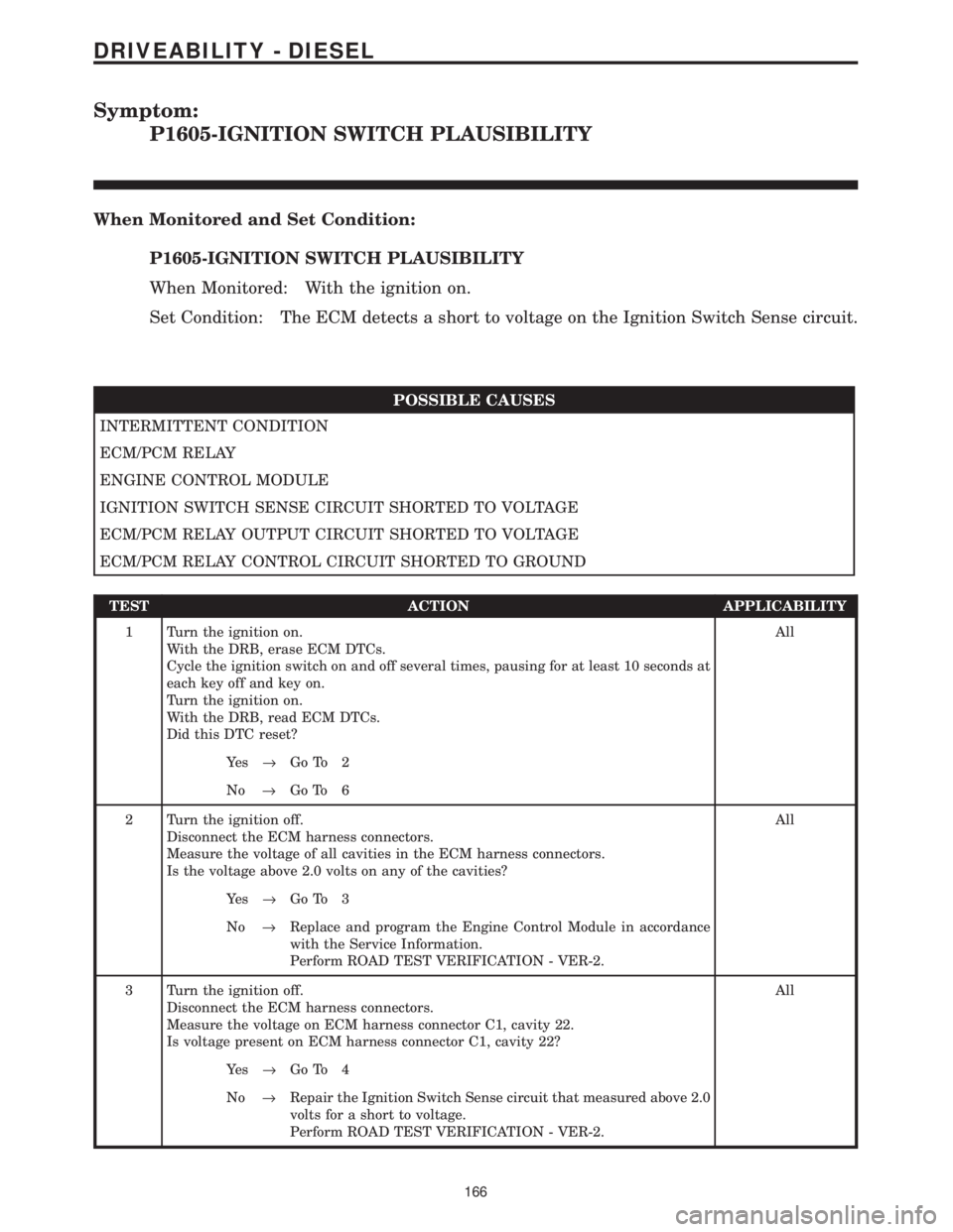
Symptom:
P1605-IGNITION SWITCH PLAUSIBILITY
When Monitored and Set Condition:
P1605-IGNITION SWITCH PLAUSIBILITY
When Monitored: With the ignition on.
Set Condition: The ECM detects a short to voltage on the Ignition Switch Sense circuit.
POSSIBLE CAUSES
INTERMITTENT CONDITION
ECM/PCM RELAY
ENGINE CONTROL MODULE
IGNITION SWITCH SENSE CIRCUIT SHORTED TO VOLTAGE
ECM/PCM RELAY OUTPUT CIRCUIT SHORTED TO VOLTAGE
ECM/PCM RELAY CONTROL CIRCUIT SHORTED TO GROUND
TEST ACTION APPLICABILITY
1 Turn the ignition on.
With the DRB, erase ECM DTCs.
Cycle the ignition switch on and off several times, pausing for at least 10 seconds at
each key off and key on.
Turn the ignition on.
With the DRB, read ECM DTCs.
Did this DTC reset?All
Ye s®Go To 2
No®Go To 6
2 Turn the ignition off.
Disconnect the ECM harness connectors.
Measure the voltage of all cavities in the ECM harness connectors.
Is the voltage above 2.0 volts on any of the cavities?All
Ye s®Go To 3
No®Replace and program the Engine Control Module in accordance
with the Service Information.
Perform ROAD TEST VERIFICATION - VER-2.
3 Turn the ignition off.
Disconnect the ECM harness connectors.
Measure the voltage on ECM harness connector C1, cavity 22.
Is voltage present on ECM harness connector C1, cavity 22?All
Ye s®Go To 4
No®Repair the Ignition Switch Sense circuit that measured above 2.0
volts for a short to voltage.
Perform ROAD TEST VERIFICATION - VER-2.
166
DRIVEABILITY - DIESEL
Page 1440 of 4284
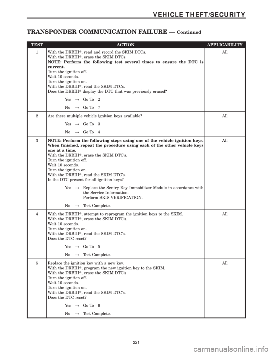
TEST ACTION APPLICABILITY
1 With the DRBIIIt, read and record the SKIM DTCs.
With the DRBIIIt, erase the SKIM DTCs.
NOTE: Perform the following test several times to ensure the DTC is
current.
Turn the ignition off.
Wait 10 seconds.
Turn the ignition on.
With the DRBIIIt, read the SKIM DTCs.
Does the DRBIIItdisplay the DTC that was previously erased?All
Ye s®Go To 2
No®Go To 7
2 Are there multiple vehicle ignition keys available? All
Ye s®Go To 3
No®Go To 4
3NOTE: Perform the following steps using one of the vehicle ignition keys.
When finished, repeat the procedure using each of the other vehicle keys
one at a time.
With the DRBIIIt, erase the SKIM DTC's.
Turn the ignition off.
Wait 10 seconds.
Turn the ignition on.
With the DRBIIIt, read the SKIM DTC's.
Is the DTC present for all ignition keys?All
Ye s®Replace the Sentry Key Immobilizer Module in accordance with
the Service Information.
Perform SKIS VERIFICATION.
No®Test Complete.
4 With the DRBIIIt, attempt to reprogram the ignition keys to the SKIM.
With the DRBIIIt, erase the SKIM DTC's.
Wait 10 seconds.
Turn the ignition on.
With the DRBIIIt, read the SKIM DTC's.
Does the DTC reset?All
Ye s®Go To 5
No®Test Complete.
5 Replace the ignition key with a new key.
With the DRBIIIt, program the new ignition key to the SKIM.
With the DRBIIIt, erase the SKIM DTC's
Turn the ignition off.
Wait 10 seconds.
Turn the ignition on.
With the DRBIIIt, read the SKIM DTC's.
Does the DTC reset?All
Ye s®Go To 6
No®Test Complete.
221
VEHICLE THEFT/SECURITY
TRANSPONDER COMMUNICATION FAILURE ÐContinued
Page 1442 of 4284
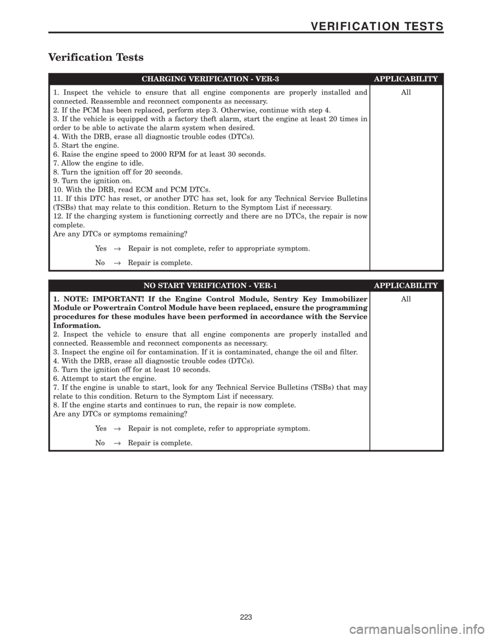
Verification Tests
CHARGING VERIFICATION - VER-3 APPLICABILITY
1. Inspect the vehicle to ensure that all engine components are properly installed and
connected. Reassemble and reconnect components as necessary.
2. If the PCM has been replaced, perform step 3. Otherwise, continue with step 4.
3. If the vehicle is equipped with a factory theft alarm, start the engine at least 20 times in
order to be able to activate the alarm system when desired.
4. With the DRB, erase all diagnostic trouble codes (DTCs).
5. Start the engine.
6. Raise the engine speed to 2000 RPM for at least 30 seconds.
7. Allow the engine to idle.
8. Turn the ignition off for 20 seconds.
9. Turn the ignition on.
10. With the DRB, read ECM and PCM DTCs.
11. If this DTC has reset, or another DTC has set, look for any Technical Service Bulletins
(TSBs) that may relate to this condition. Return to the Symptom List if necessary.
12. If the charging system is functioning correctly and there are no DTCs, the repair is now
complete.
Are any DTCs or symptoms remaining?All
Ye s®Repair is not complete, refer to appropriate symptom.
No®Repair is complete.
NO START VERIFICATION - VER-1 APPLICABILITY
1. NOTE: IMPORTANT! If the Engine Control Module, Sentry Key Immobilizer
Module or Powertrain Control Module have been replaced, ensure the programming
procedures for these modules have been performed in accordance with the Service
Information.
2. Inspect the vehicle to ensure that all engine components are properly installed and
connected. Reassemble and reconnect components as necessary.
3. Inspect the engine oil for contamination. If it is contaminated, change the oil and filter.
4. With the DRB, erase all diagnostic trouble codes (DTCs).
5. Turn the ignition off for at least 10 seconds.
6. Attempt to start the engine.
7. If the engine is unable to start, look for any Technical Service Bulletins (TSBs) that may
relate to this condition. Return to the Symptom List if necessary.
8. If the engine starts and continues to run, the repair is now complete.
Are any DTCs or symptoms remaining?All
Ye s®Repair is not complete, refer to appropriate symptom.
No®Repair is complete.
223
VERIFICATION TESTS
Page 1443 of 4284
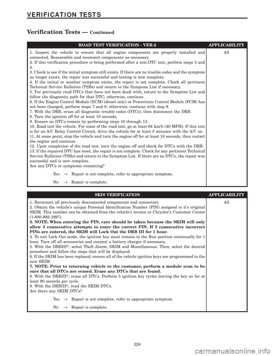
ROAD TEST VERIFICATION - VER-2 APPLICABILITY
1. Inspect the vehicle to ensure that all engine components are properly installed and
connected. Reassemble and reconnect components as necessary.
2. If this verification procedure is being performed after a non-DTC test, perform steps 3 and
4.
3. Check to see if the initial symptom still exists. If there are no trouble codes and the symptom
no longer exists, the repair was successful and testing is now complete.
4. If the initial or another symptom exists, the repair is not complete. Check all pertinent
Technical Service Bulletins (TSBs) and return to the Symptom List if necessary.
5. For previously read DTCs that have not been dealt with, return to the Symptom List and
follow the diagnostic path for that DTC; otherwise, continue.
6. If the Engine Control Module (ECM) (diesel only) or Powertrain Control Module (PCM) has
not been changed, perform steps 7 and 8, otherwise, continue with step 9.
7. With the DRB, erase all diagnostic trouble codes (DTCs), then disconnect the DRB.
8. Turn the ignition off for at least 10 seconds.
9. Ensure no DTCs remain by performing steps 10 through 13.
10. Road test the vehicle. For some of the road test, go at least 64 km/h (40 MPH). If this test
is for an A/C Relay Control Circuit, drive the vehicle for at least 5 minutes with the A/C on.
11. At some point, stop the vehicle and turn the engine off for at least 10 seconds, then restart
the engine and continue.
12. Upon completion of the road test, turn the engine off and check for DTCs with the DRB.
13. If the repaired DTC has reset, the repair is not complete. Check for any pertinent Technical
Service Bulletins (TSBs) and return to the Symptom List. If there are no DTCs, the repair was
successful and is now complete.
Are any DTCs or symptoms remaining?All
Ye s®Repair is not complete, refer to appropriate symptom.
No®Repair is complete.
SKIS VERIFICATION APPLICABILITY
1. Reconnect all previously disconnected components and connectors.
2. Obtain the vehicle's unique Personal Identification Number (PIN) assigned to it's original
SKIM. This number can be obtained from the vehicle's invoice or Chrysler's Customer Center
(1-800-992-1997).
3. NOTE: When entering the PIN, care should be taken because the SKIM will only
allow 3 consecutive attempts to enter the correct PIN. If 3 consecutive incorrect
PINs are entered, the SKIM will Lock Out the DRB III for 1 hour.
4. To exit Lock Out mode, the ignition key must remain in the Run position continually for 1
hour. Turn off all accessories and connect a battery charger if necessary.
5. With the DRBIIIt, select Theft Alarm, SKIM and Miscellaneous. Then, select the desired
procedure and follow the steps that will be displayed.
6. If the SKIM has been replaced, ensure all of the vehicle ignition keys are programmed to the
new SKIM.
7. NOTE: Prior to returning vehicle to the customer, perform a module scan to be
sure that all DTCs are erased. Erase any DTCs that are found.
8. With the DRBIIIt, erase all DTCs. Perform 5 ignition key cycles leaving the key on for at
least 90 seconds per cycle.
9. With the DRBIIIt, read the SKIM DTCs.
Are there any SKIM DTCs?All
Ye s®Repair is not complete, refer to appropriate symptom.
No®Repair is complete.
224
VERIFICATION TESTS
Verification Tests ÐContinued
Page 1522 of 4284
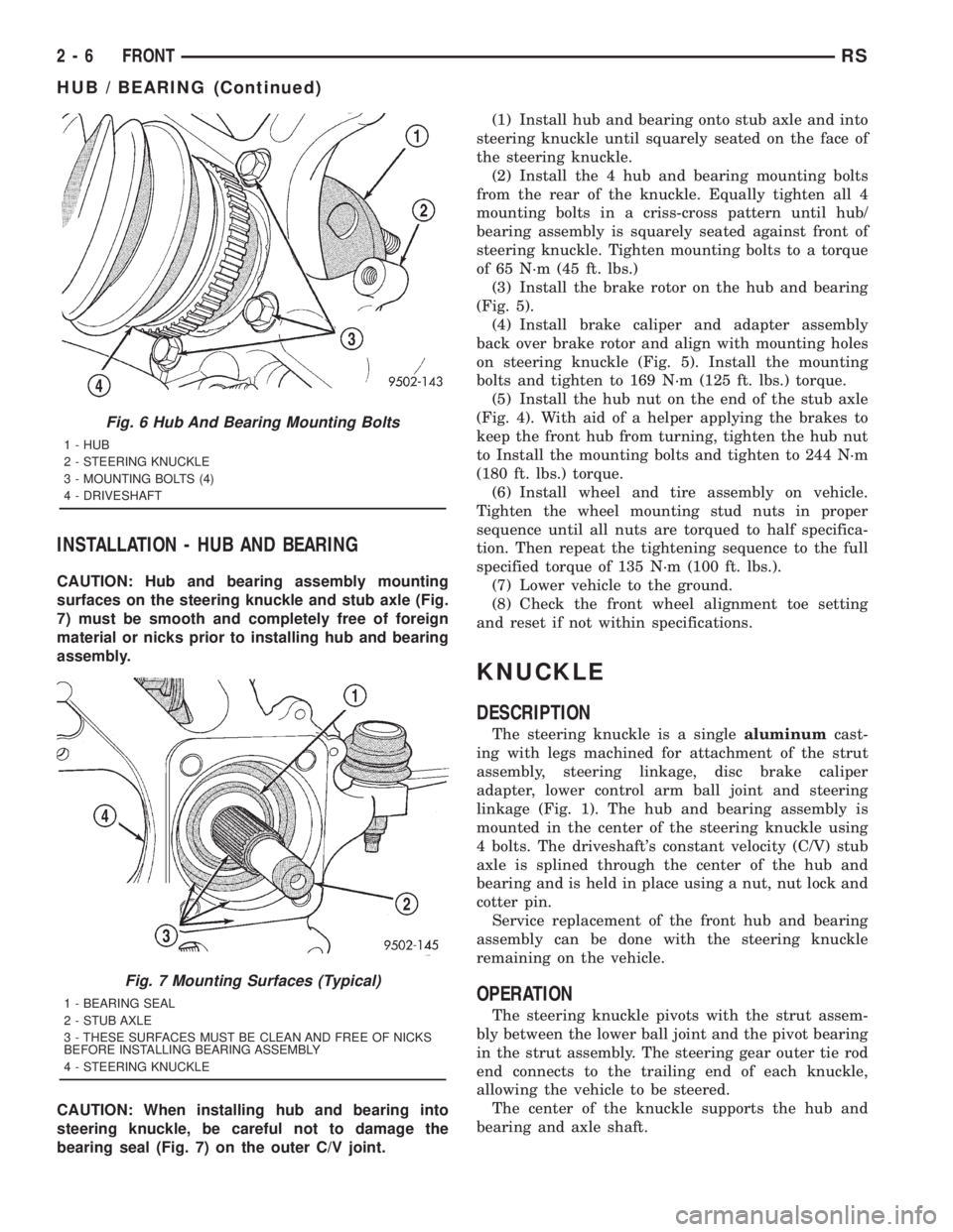
INSTALLATION - HUB AND BEARING
CAUTION: Hub and bearing assembly mounting
surfaces on the steering knuckle and stub axle (Fig.
7) must be smooth and completely free of foreign
material or nicks prior to installing hub and bearing
assembly.
CAUTION: When installing hub and bearing into
steering knuckle, be careful not to damage the
bearing seal (Fig. 7) on the outer C/V joint.(1) Install hub and bearing onto stub axle and into
steering knuckle until squarely seated on the face of
the steering knuckle.
(2) Install the 4 hub and bearing mounting bolts
from the rear of the knuckle. Equally tighten all 4
mounting bolts in a criss-cross pattern until hub/
bearing assembly is squarely seated against front of
steering knuckle. Tighten mounting bolts to a torque
of 65 N´m (45 ft. lbs.)
(3) Install the brake rotor on the hub and bearing
(Fig. 5).
(4) Install brake caliper and adapter assembly
back over brake rotor and align with mounting holes
on steering knuckle (Fig. 5). Install the mounting
bolts and tighten to 169 N´m (125 ft. lbs.) torque.
(5) Install the hub nut on the end of the stub axle
(Fig. 4). With aid of a helper applying the brakes to
keep the front hub from turning, tighten the hub nut
to Install the mounting bolts and tighten to 244 N´m
(180 ft. lbs.) torque.
(6) Install wheel and tire assembly on vehicle.
Tighten the wheel mounting stud nuts in proper
sequence until all nuts are torqued to half specifica-
tion. Then repeat the tightening sequence to the full
specified torque of 135 N´m (100 ft. lbs.).
(7) Lower vehicle to the ground.
(8) Check the front wheel alignment toe setting
and reset if not within specifications.
KNUCKLE
DESCRIPTION
The steering knuckle is a singlealuminumcast-
ing with legs machined for attachment of the strut
assembly, steering linkage, disc brake caliper
adapter, lower control arm ball joint and steering
linkage (Fig. 1). The hub and bearing assembly is
mounted in the center of the steering knuckle using
4 bolts. The driveshaft's constant velocity (C/V) stub
axle is splined through the center of the hub and
bearing and is held in place using a nut, nut lock and
cotter pin.
Service replacement of the front hub and bearing
assembly can be done with the steering knuckle
remaining on the vehicle.
OPERATION
The steering knuckle pivots with the strut assem-
bly between the lower ball joint and the pivot bearing
in the strut assembly. The steering gear outer tie rod
end connects to the trailing end of each knuckle,
allowing the vehicle to be steered.
The center of the knuckle supports the hub and
bearing and axle shaft.
Fig. 6 Hub And Bearing Mounting Bolts
1 - HUB
2 - STEERING KNUCKLE
3 - MOUNTING BOLTS (4)
4 - DRIVESHAFT
Fig. 7 Mounting Surfaces (Typical)
1 - BEARING SEAL
2 - STUB AXLE
3 - THESE SURFACES MUST BE CLEAN AND FREE OF NICKS
BEFORE INSTALLING BEARING ASSEMBLY
4 - STEERING KNUCKLE
2 - 6 FRONTRS
HUB / BEARING (Continued)
Page 1812 of 4284
(4) Connect battery negative cable.
QUARTER PANEL SPEAKER
REMOVAL
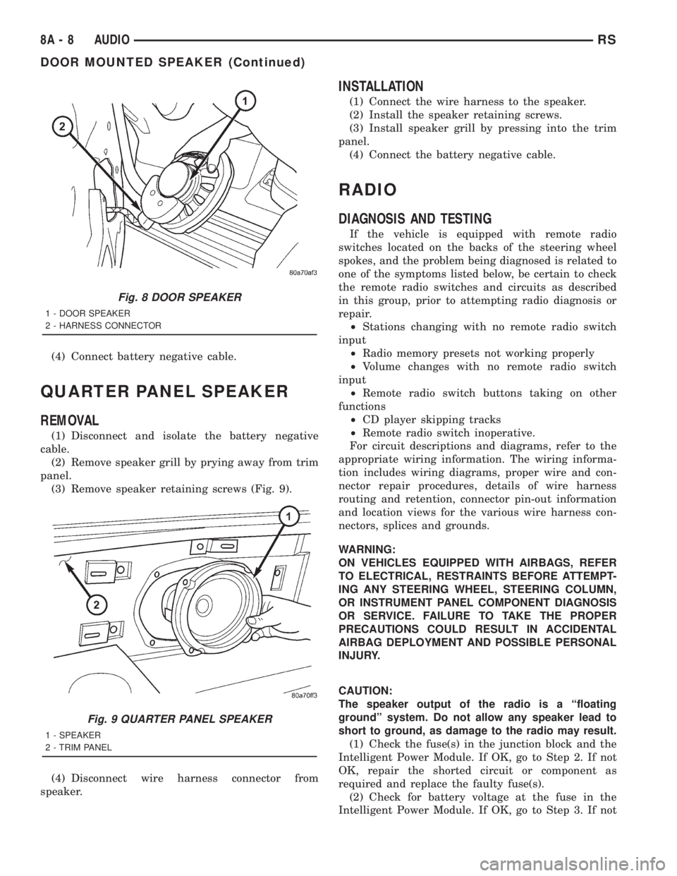
(1) Disconnect and isolate the battery negative
cable.
(2) Remove speaker grill by prying away from trim
panel.
(3) Remove speaker retaining screws (Fig. 9).
(4) Disconnect wire harness connector from
speaker.
INSTALLATION
(1) Connect the wire harness to the speaker.
(2) Install the speaker retaining screws.
(3) Install speaker grill by pressing into the trim
panel.
(4) Connect the battery negative cable.
RADIO
DIAGNOSIS AND TESTING
If the vehicle is equipped with remote radio
switches located on the backs of the steering wheel
spokes, and the problem being diagnosed is related to
one of the symptoms listed below, be certain to check
the remote radio switches and circuits as described
in this group, prior to attempting radio diagnosis or
repair.
²Stations changing with no remote radio switch
input
²Radio memory presets not working properly
²Volume changes with no remote radio switch
input
²Remote radio switch buttons taking on other
functions
²CD player skipping tracks
²Remote radio switch inoperative.
For circuit descriptions and diagrams, refer to the
appropriate wiring information. The wiring informa-
tion includes wiring diagrams, proper wire and con-
nector repair procedures, details of wire harness
routing and retention, connector pin-out information
and location views for the various wire harness con-
nectors, splices and grounds.
WARNING:
ON VEHICLES EQUIPPED WITH AIRBAGS, REFER
TO ELECTRICAL, RESTRAINTS BEFORE ATTEMPT-
ING ANY STEERING WHEEL, STEERING COLUMN,
OR INSTRUMENT PANEL COMPONENT DIAGNOSIS
OR SERVICE. FAILURE TO TAKE THE PROPER
PRECAUTIONS COULD RESULT IN ACCIDENTAL
AIRBAG DEPLOYMENT AND POSSIBLE PERSONAL
INJURY.
CAUTION:
The speaker output of the radio is a ªfloating
groundº system. Do not allow any speaker lead to
short to ground, as damage to the radio may result.
(1) Check the fuse(s) in the junction block and the
Intelligent Power Module. If OK, go to Step 2. If not
OK, repair the shorted circuit or component as
required and replace the faulty fuse(s).
(2) Check for battery voltage at the fuse in the
Intelligent Power Module. If OK, go to Step 3. If not
Fig. 8 DOOR SPEAKER
1 - DOOR SPEAKER
2 - HARNESS CONNECTOR
Fig. 9 QUARTER PANEL SPEAKER
1 - SPEAKER
2 - TRIM PANEL
8A - 8 AUDIORS
DOOR MOUNTED SPEAKER (Continued)
Page 1852 of 4284
STANDARD PROCEDURE - TCC BREAK-IN
VIEW/RESTART PROCEDURE
The Transmission Control Module (TCM) employs
a strategy which modifies torque converter clutch
(TCC) operation. This strategy conditions the torque
converter clutch disc for optimum converter clutch
engagement and feel throughout the life of the trans-
axle. The cycle inhibits FEMCC until six hours of
PEMCC operation have taken place, or the vehicle
has been driven 6,035 km (3750 miles). The cycle
automatically terminates when either the time or
mileage has been achieved, however, the mileage
may vary slightly from vehicle to vehicle.
The TCC break-in cycle must be restarted using
the DRB Scan Tool, and upon:
²Replacement of TCM on vehicle with less than
6,035 km (3750 miles) or less than 6 hours of
PEMCC operation
²Replacement of torque converter assembly at
any vehicle mileage
NOTE: Failure to restart the TCC Break-In Cycle
upon TCM replacement in vehicles with less than
six hours of PEMCC or less than 6,035 km (3750
miles), or upon torque converter replacement at any
mileage, may result in vehicle shudder during cer-
tain operating conditions.
Procedure
The DRB Scan Tool is required to view and/or
restart the TCC Break-In cycle.
(1) Connect the DRB Scan Tool to the vehicle diag-
nostic connector.
(2) Navigate to ªTCC Break-Inº via Transmission/
Transmission Control Module/Miscellaneous.
(3) View or Start TCC Break-In as prompted by
DRB menu.
REMOVAL
NOTE: If transmission control module is being
replaced with a new or replacement unit, the Pinion
Factor and Quick Learn procedures must be per-
formed. (Refer to 8 - ELECTRICAL/ELECTRONIC
CONTROL MODULES/TRANSMISSION CONTROL
MODULE - STANDARD PROCEDURE) (Refer to 8 -
ELECTRICAL/ELECTRONIC CONTROL MODULES/
TRANSMISSION CONTROL MODULE - STANDARD
PROCEDURE) If vehicle has less than 6,035 km
(3750 miles), the Torque Converter Clutch (TCC)
Break-In Strategy reset procedure must also be per-
formed. (Refer to 8 - ELECTRICAL/ELECTRONIC
CONTROL MODULES/TRANSMISSION CONTROL
MODULE - STANDARD PROCEDURE)(1) Disconnect battery negative cable.
(2) Raise vehicle on hoist.
(3) Remove left front tire/wheel assembly.
(4) Pull back splash shield to gain access to TCM
location.
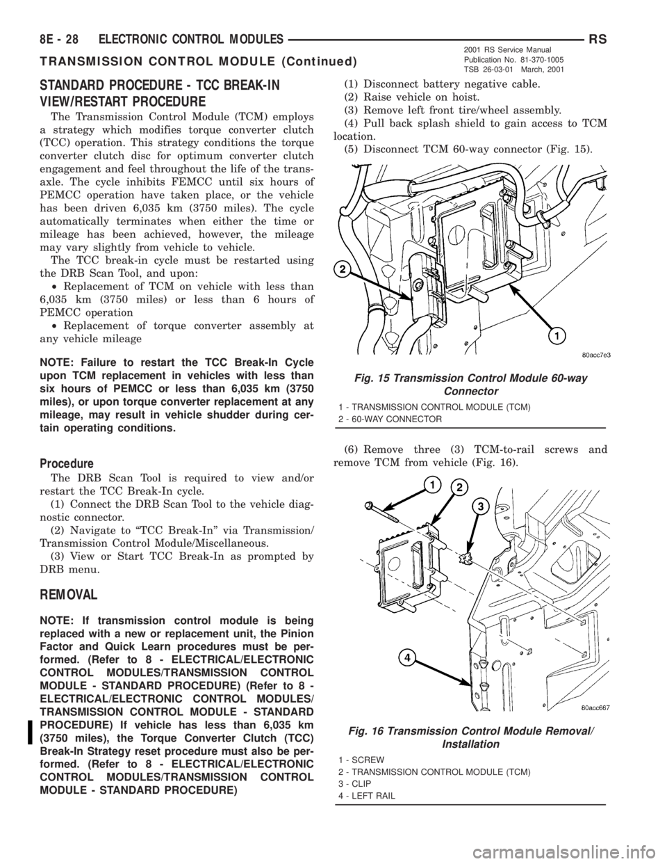
(5) Disconnect TCM 60-way connector (Fig. 15).
(6) Remove three (3) TCM-to-rail screws and
remove TCM from vehicle (Fig. 16).
Fig. 15 Transmission Control Module 60-way
Connector
1 - TRANSMISSION CONTROL MODULE (TCM)
2 - 60-WAY CONNECTOR
Fig. 16 Transmission Control Module Removal/
Installation
1 - SCREW
2 - TRANSMISSION CONTROL MODULE (TCM)
3 - CLIP
4 - LEFT RAIL
8E - 28 ELECTRONIC CONTROL MODULESRS
TRANSMISSION CONTROL MODULE (Continued)
2001 RS Service Manual
Publication No. 81-370-1005
TSB 26-03-01 March, 2001
Page 1853 of 4284
INSTALLATION
NOTE: If transmission control module is being
replaced with a new or replacement unit, the Pinion
Factor and Quick Learn procedures must be per-
formed. (Refer to 8 - ELECTRICAL/ELECTRONIC
CONTROL MODULES/TRANSMISSION CONTROL
MODULE - STANDARD PROCEDURE) (Refer to 8 -
ELECTRICAL/ELECTRONIC CONTROL MODULES/
TRANSMISSION CONTROL MODULE - STANDARD
PROCEDURE)
NOTE: If TCM is replaced and vehicle has less than
6,035 km (3750 miles), the Torque Converter Clutch
(TCC) Break-In Strategy reset procedure must also
be performed. (Refer to 8 - ELECTRICAL/ELEC-
TRONIC CONTROL MODULES/TRANSMISSION
CONTROL MODULE - STANDARD PROCEDURE)
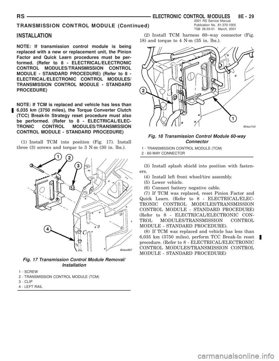
(1) Install TCM into position (Fig. 17). Install
three (3) screws and torque to 3 N´m (30 in. lbs.).(2) Install TCM harness 60±way connector (Fig.
18) and torque to 4 N´m (35 in. lbs.).
(3) Install splash shield into position with fasten-
ers.
(4) Install left front wheel/tire assembly.
(5) Lower vehicle.
(6) Connect battery negative cable.
(7) If TCM was replaced, reset Pinion Factor and
Quick Learn. (Refer to 8 - ELECTRICAL/ELEC-
TRONIC CONTROL MODULES/TRANSMISSION
CONTROL MODULE - STANDARD PROCEDURE)
(Refer to 8 - ELECTRICAL/ELECTRONIC CON-
TROL MODULES/TRANSMISSION CONTROL
MODULE - STANDARD PROCEDURE).
(8) If TCM was replaced and vehicle has less than
6,035 km (3750 miles), perform TCC Break-In reset
procedure. (Refer to 8 - ELECTRICAL/ELECTRONIC
CONTROL MODULES/TRANSMISSION CONTROL
MODULE - STANDARD PROCEDURE)
Fig. 17 Transmission Control Module Removal/
Installation
1 - SCREW
2 - TRANSMISSION CONTROL MODULE (TCM)
3 - CLIP
4 - LEFT RAIL
Fig. 18 Transmission Control Module 60-way
Connector
1 - TRANSMISSION CONTROL MODULE (TCM)
2 - 60-WAY CONNECTOR
RSELECTRONIC CONTROL MODULES8E-29
TRANSMISSION CONTROL MODULE (Continued)
2001 RS Service Manual
Publication No. 81-370-1005
TSB 26-03-01 March, 2001