2001 CHRYSLER VOYAGER service reset
[x] Cancel search: service resetPage 396 of 4284

Symptom:
PCM MESSAGES NOT RECEIVED
When Monitored and Set Condition:
PCM MESSAGES NOT RECEIVED
When Monitored: With the ignition in run, and the IOD fuse installed.
Set Condition: The BCM does not receive any messages from the PCM for at least 5
seconds.
POSSIBLE CAUSES
PCM MESSAGE NOT RECEIVED
ATTEMPT TO COMMUNICATE WITH THE PCM
PCI BUS CIRCUIT OPEN
POWERTRAIN CONTROL MODULE
TEST ACTION APPLICABILITY
1 Turn the ignition on.
With the DRB, enter Instrument Cluster, System Tests then PCM Monitor.
Does the DRB display: PCM is active on BUS?All
Ye s®Erase the DTC, if DTC resets, replace the Body Control Module.
Perform BODY VERIFICATION TEST - VER 1.
No®Go To 2
2 Turn the ignition on.
With the DRB, attempt to communicate with the PCM.
Was the DRB able to communicate with the PCM?All
Ye s®Go To 3
No®Refer to the communication category and perform the appropriate
symptom.
Perform BODY VERIFICATION TEST - VER 1.
3 Turn the ignition off.
Disconnect the PCM C2 harness connector.
Connect the diagnostic junction port tester #8339 to the diagnostic junction port.
Note: Do not connect the tester to the DRB.
Measure the resistance of the PCI Bus circuit between the diagnostic junction port
tester and the PCM C2 connector.
Is the resistance below 5.0 ohms?All
Ye s®Replace and program the Powertrain Control Module in accor-
dance with the Service Information.
Perform BODY VERIFICATION TEST - VER 1.
No®Repair the PCI Bus circuit for an open.
Perform BODY VERIFICATION TEST - VER 1.
367
COMMUNICATION
Page 556 of 4284

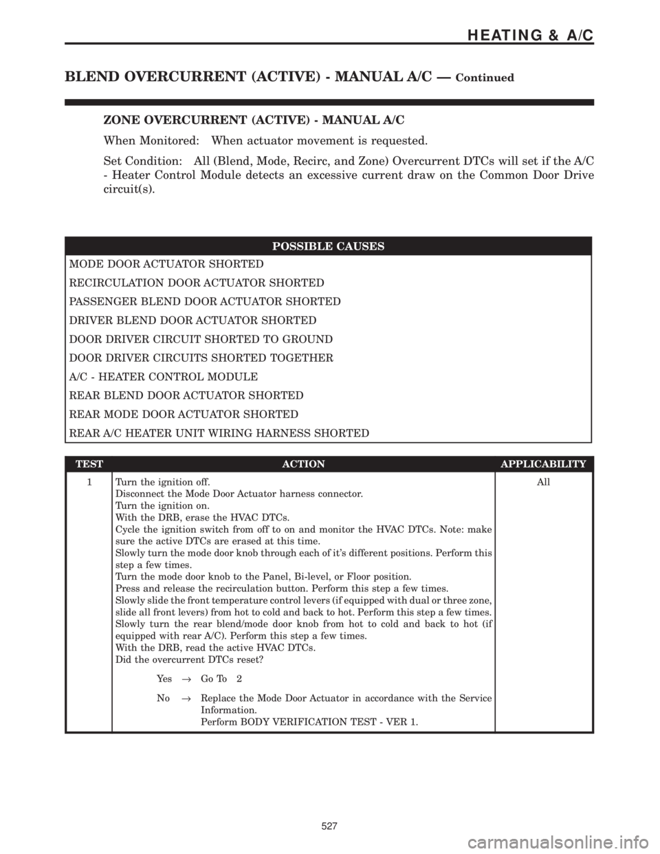
ZONE OVERCURRENT (ACTIVE) - MANUAL A/C
When Monitored: When actuator movement is requested.
Set Condition: All (Blend, Mode, Recirc, and Zone) Overcurrent DTCs will set if the A/C
- Heater Control Module detects an excessive current draw on the Common Door Drive
circuit(s).
POSSIBLE CAUSES
MODE DOOR ACTUATOR SHORTED
RECIRCULATION DOOR ACTUATOR SHORTED
PASSENGER BLEND DOOR ACTUATOR SHORTED
DRIVER BLEND DOOR ACTUATOR SHORTED
DOOR DRIVER CIRCUIT SHORTED TO GROUND
DOOR DRIVER CIRCUITS SHORTED TOGETHER
A/C - HEATER CONTROL MODULE
REAR BLEND DOOR ACTUATOR SHORTED
REAR MODE DOOR ACTUATOR SHORTED
REAR A/C HEATER UNIT WIRING HARNESS SHORTED
TEST ACTION APPLICABILITY
1 Turn the ignition off.
Disconnect the Mode Door Actuator harness connector.
Turn the ignition on.
With the DRB, erase the HVAC DTCs.
Cycle the ignition switch from off to on and monitor the HVAC DTCs. Note: make
sure the active DTCs are erased at this time.
Slowly turn the mode door knob through each of it's different positions. Perform this
step a few times.
Turn the mode door knob to the Panel, Bi-level, or Floor position.
Press and release the recirculation button. Perform this step a few times.
Slowly slide the front temperature control levers (if equipped with dual or three zone,
slide all front levers) from hot to cold and back to hot. Perform this step a few times.
Slowly turn the rear blend/mode door knob from hot to cold and back to hot (if
equipped with rear A/C). Perform this step a few times.
With the DRB, read the active HVAC DTCs.
Did the overcurrent DTCs reset?All
Ye s®Go To 2
No®Replace the Mode Door Actuator in accordance with the Service
Information.
Perform BODY VERIFICATION TEST - VER 1.
527
HEATING & A/C
BLEND OVERCURRENT (ACTIVE) - MANUAL A/C ÐContinued
Page 557 of 4284

TEST ACTION APPLICABILITY
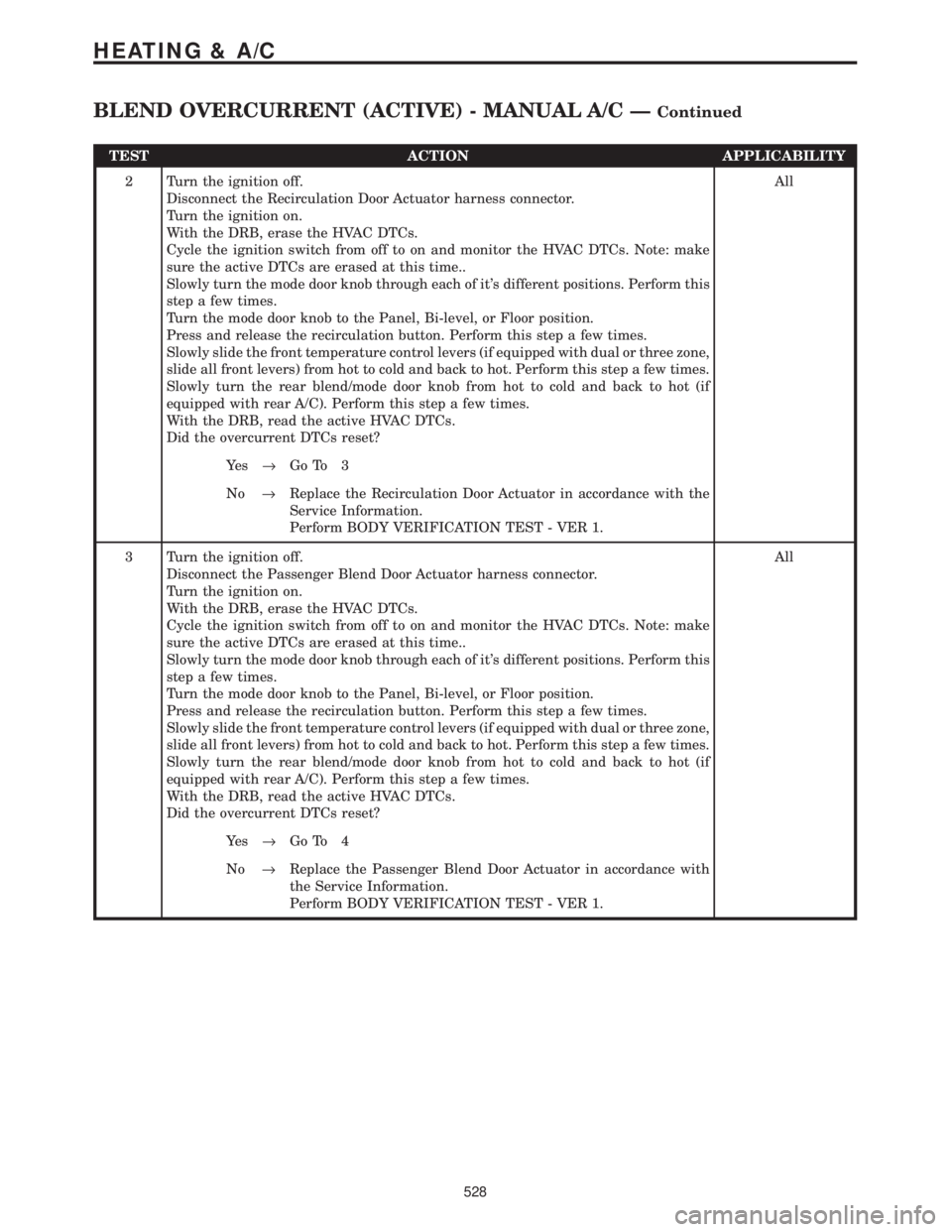
2 Turn the ignition off.
Disconnect the Recirculation Door Actuator harness connector.
Turn the ignition on.
With the DRB, erase the HVAC DTCs.
Cycle the ignition switch from off to on and monitor the HVAC DTCs. Note: make
sure the active DTCs are erased at this time..
Slowly turn the mode door knob through each of it's different positions. Perform this
step a few times.
Turn the mode door knob to the Panel, Bi-level, or Floor position.
Press and release the recirculation button. Perform this step a few times.
Slowly slide the front temperature control levers (if equipped with dual or three zone,
slide all front levers) from hot to cold and back to hot. Perform this step a few times.
Slowly turn the rear blend/mode door knob from hot to cold and back to hot (if
equipped with rear A/C). Perform this step a few times.
With the DRB, read the active HVAC DTCs.
Did the overcurrent DTCs reset?All
Ye s®Go To 3
No®Replace the Recirculation Door Actuator in accordance with the
Service Information.
Perform BODY VERIFICATION TEST - VER 1.
3 Turn the ignition off.
Disconnect the Passenger Blend Door Actuator harness connector.
Turn the ignition on.
With the DRB, erase the HVAC DTCs.
Cycle the ignition switch from off to on and monitor the HVAC DTCs. Note: make
sure the active DTCs are erased at this time..
Slowly turn the mode door knob through each of it's different positions. Perform this
step a few times.
Turn the mode door knob to the Panel, Bi-level, or Floor position.
Press and release the recirculation button. Perform this step a few times.
Slowly slide the front temperature control levers (if equipped with dual or three zone,
slide all front levers) from hot to cold and back to hot. Perform this step a few times.
Slowly turn the rear blend/mode door knob from hot to cold and back to hot (if
equipped with rear A/C). Perform this step a few times.
With the DRB, read the active HVAC DTCs.
Did the overcurrent DTCs reset?All
Ye s®Go To 4
No®Replace the Passenger Blend Door Actuator in accordance with
the Service Information.
Perform BODY VERIFICATION TEST - VER 1.
528
HEATING & A/C
BLEND OVERCURRENT (ACTIVE) - MANUAL A/C ÐContinued
Page 558 of 4284

TEST ACTION APPLICABILITY
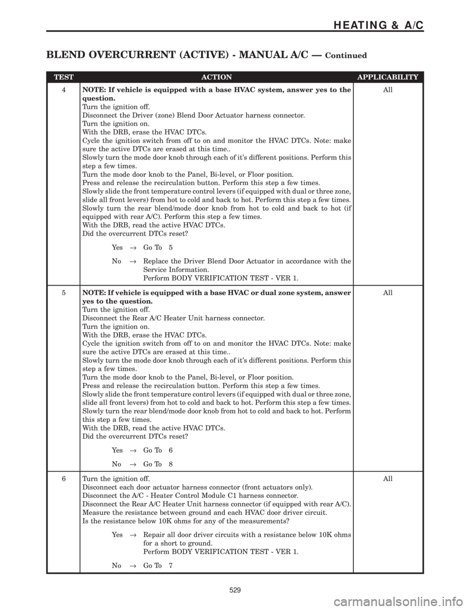
4NOTE: If vehicle is equipped with a base HVAC system, answer yes to the
question.
Turn the ignition off.
Disconnect the Driver (zone) Blend Door Actuator harness connector.
Turn the ignition on.
With the DRB, erase the HVAC DTCs.
Cycle the ignition switch from off to on and monitor the HVAC DTCs. Note: make
sure the active DTCs are erased at this time..
Slowly turn the mode door knob through each of it's different positions. Perform this
step a few times.
Turn the mode door knob to the Panel, Bi-level, or Floor position.
Press and release the recirculation button. Perform this step a few times.
Slowly slide the front temperature control levers (if equipped with dual or three zone,
slide all front levers) from hot to cold and back to hot. Perform this step a few times.
Slowly turn the rear blend/mode door knob from hot to cold and back to hot (if
equipped with rear A/C). Perform this step a few times.
With the DRB, read the active HVAC DTCs.
Did the overcurrent DTCs reset?All
Ye s®Go To 5
No®Replace the Driver Blend Door Actuator in accordance with the
Service Information.
Perform BODY VERIFICATION TEST - VER 1.
5NOTE: If vehicle is equipped with a base HVAC or dual zone system, answer
yes to the question.
Turn the ignition off.
Disconnect the Rear A/C Heater Unit harness connector.
Turn the ignition on.
With the DRB, erase the HVAC DTCs.
Cycle the ignition switch from off to on and monitor the HVAC DTCs. Note: make
sure the active DTCs are erased at this time..
Slowly turn the mode door knob through each of it's different positions. Perform this
step a few times.
Turn the mode door knob to the Panel, Bi-level, or Floor position.
Press and release the recirculation button. Perform this step a few times.
Slowly slide the front temperature control levers (if equipped with dual or three zone,
slide all front levers) from hot to cold and back to hot. Perform this step a few times.
Slowly turn the rear blend/mode door knob from hot to cold and back to hot. Perform
this step a few times.
With the DRB, read the active HVAC DTCs.
Did the overcurrent DTCs reset?All
Ye s®Go To 6
No®Go To 8
6 Turn the ignition off.
Disconnect each door actuator harness connector (front actuators only).
Disconnect the A/C - Heater Control Module C1 harness connector.
Disconnect the Rear A/C Heater Unit harness connector (if equipped with rear A/C).
Measure the resistance between ground and each HVAC door driver circuit.
Is the resistance below 10K ohms for any of the measurements?All
Ye s®Repair all door driver circuits with a resistance below 10K ohms
for a short to ground.
Perform BODY VERIFICATION TEST - VER 1.
No®Go To 7
529
HEATING & A/C
BLEND OVERCURRENT (ACTIVE) - MANUAL A/C ÐContinued
Page 559 of 4284

TEST ACTION APPLICABILITY
7 Turn the ignition off.
Disconnect each door actuator harness connector (front actuators only).
Disconnect the A/C - Heater Control Module C1 harness connector.
Disconnect the Rear A/C Heater Unit harness connector (if equipped with rear A/C).
Measure the resistance between the Common Door Driver circuit and each other door
driver circuit.
Measure the resistance between the Recirculation Door Driver circuit and each other
door driver circuit.
Measure the resistance between the Mode Door Driver circuit and each other door
driver circuit.
Measure the resistance between the Passenger Blend Air Door Driver circuit and
each other door driver circuit.
Measure the resistance between the Driver Blend Door Driver circuit and each other
door driver circuit (if equipped with dual or 3 zone).
Measure the resistance between the Rear Common Door Driver circuit and each
other door driver circuit (if equipped with rear A/C).
Measure the resistance between the Rear Blend Door Driver circuit and each other
door driver circuit (if equipped with rear A/C).
Measure the resistance between the Rear Mode Door Driver circuit and each other
door driver circuit (if equipped with rear A/C).
Is the resistance below 10K ohms for any of the measurements?All
Ye s®Repair the door driver circuits that measured below 10K ohms for
a short to each other.
Perform BODY VERIFICATION TEST - VER 1.
No®Replace the A/C - Heater Control Module in accordance with the
Service Information.
Perform BODY VERIFICATION TEST - VER 1.
8 Turn the ignition off.
Reconnect the Rear A/C Heater Unit harness connector.
Disconnect the Rear Blend Door Actuator harness connector.
Turn the ignition on.
With the DRB, erase the HVAC DTCs.
Cycle the ignition switch from off to on and monitor the HVAC DTCs. Note: make
sure the active DTCs are erased at this time.
Slowly turn the mode door knob through each of it's different positions. Perform this
step a few times.
Turn the mode door knob to the Panel, Bi-level, or Floor position.
Press and release the recirculation button. Perform this step a few times.
Slowly slide the front temperature control levers (if equipped with dual or three zone,
slide all front levers) from hot to cold and back to hot. Perform this step a few times.
Slowly turn the rear blend/mode door knob from hot to cold and back to hot. Perform
this step a few times.
With the DRB, read the active HVAC DTCs.
Did the overcurrent DTCs reset?All
Ye s®Go To 9
No®Replace the Rear Blend Door Actuator in accordance with the
Service Information.
Perform BODY VERIFICATION TEST - VER 1.
530
HEATING & A/C
BLEND OVERCURRENT (ACTIVE) - MANUAL A/C ÐContinued
Page 560 of 4284

TEST ACTION APPLICABILITY
9 Turn the ignition off.
Reconnect the Rear A/C Heater Unit harness connector.
Disconnect the Rear Mode Door Actuator harness connector.
Turn the ignition on.
With the DRB, erase the HVAC DTCs.
Cycle the ignition switch from off to on and monitor the HVAC DTCs. Note: make
sure the active DTCs are erased at this time.
Slowly turn the mode door knob through each of it's different positions. Perform this
step a few times.
Turn the mode door knob to the Panel, Bi-level, or Floor position.
Press and release the recirculation button. Perform this step a few times.
Slowly slide the front temperature control levers (if equipped with dual or three zone,
slide all front levers) from hot to cold and back to hot. Perform this step a few times.
Slowly turn the rear blend/mode door knob from hot to cold and back to hot. Perform
this step a few times.
With the DRB, read the active HVAC DTCs.
Did the overcurrent DTCs reset?All
Ye s®Repair the Rear A/C Heater Unit wiring harness for a short to
ground or shorted together door driver circuits between the Rear
A/C Heater Unit and the rear mode and blend doors.
Perform BODY VERIFICATION TEST - VER 1.
No®Replace the Rear Mode Door Actuator in accordance with the
Service Information.
Perform BODY VERIFICATION TEST - VER 1.
531
HEATING & A/C
BLEND OVERCURRENT (ACTIVE) - MANUAL A/C ÐContinued
Page 571 of 4284

Symptom List:
FRONT AND REAR BLOWER OUTPUT 1 OPEN
FRONT AND REAR BLOWER OUTPUT 2 OPEN
Test Note: All symptoms listed above are diagnosed using the same tests.
The title for the tests will be FRONT AND REAR BLOWER
OUTPUT 1 OPEN.
When Monitored and Set Condition:
FRONT AND REAR BLOWER OUTPUT 1 OPEN
When Monitored: Continuously.
Set Condition: If the FCM detects no voltage present on the Front/Rear Blower Motor
Relay Control circuit.
FRONT AND REAR BLOWER OUTPUT 2 OPEN
When Monitored: Continuously.
Set Condition: If the FCM detects no voltage present on the Front/Rear Blower Motor
Relay Control circuit.
POSSIBLE CAUSES
CHECK DTCS
B+ CIRCUIT OPEN
FRONT AND REAR BLOWER RELAYS OPEN
FRONT/REAR BLOWER MOTOR RELAY CONTROL CIRCUIT SHORTED TO GROUND
FRONT/REAR BLOWER MOTOR RELAY CONTROL CIRCUIT OPEN
FRONT CONTROL MODULE
TEST ACTION APPLICABILITY
1 Turn the ignition on.
NOTE: If neither DTC will reset or is active, refer to the wiring diagrams
located in the service information to help isolate a possible intermittent
condition.
With the DRB, read the FCM DTC's.
Are both the Front/Rear Blower Output 1 Open and the Front/Rear Blower Output
2 Open DTC's set?All
Ye s®Go To 2
No®Replace the Front Control Module (FCM) in accordance with the
Service Information.
Perform BODY VERIFICATION TEST - VER 1.
542
HEATING & A/C
Page 572 of 4284

TEST ACTION APPLICABILITY
2 Remove either the Front Blower Motor Relay or the Rear Blower Motor Relay, if
equipped, from the IPM.
Using a 12-volt test light connected to ground, probe cavity 86 of the blower relay
connector.
Is the test light illuminated?All
Ye s®Go To 3
No®Check the B+ feed to the Intelligent Power Module (IPM) for an
open. If OK, replace the IPM in accordance with the Service
Information.
Perform BODY VERIFICATION TEST - VER 1.
3 Turn the ignition off.
Install a substitute relay in place of the existing Front Blower Motor Relay and the
existing Rear Blower Motor Relay, if equipped.
With the DRB, erase DTCs.
Turn the ignition off, wait 30 seconds, then turn the ignition on.
With the DRB, read DTCs.
Did these DTCs reset?All
Ye s®Go To 4
No®Replace the Front Blower Motor Relay and the Rear Blower
Motor Relay, if equipped.
Perform BODY VERIFICATION TEST - VER 1.
4 Turn the ignition off.
Remove the Front Control Module from the IPM.
Remove the Front Blower Motor Relay and the Rear Blower Motor Relay, if equipped,
from the IPM.
Measure the resistance between ground and the Front/Rear Blower Motor Relay
Control circuit (FCM connector cavity 30).
Is the resistance below 5.0 ohms?All
Ye s®Replace the Intelligent Power Module (IPM) in accordance with
the Service Information.
Perform BODY VERIFICATION TEST - VER 1.
No®Go To 5
5 Turn the ignition off.
Remove the Front Control Module from the IPM.
Remove the Front Blower Motor Relay from the IPM.
Measure the resistance of the Front/Rear Blower Motor Relay Control circuit
between the FCM connector cavity 30 and the Front Blower Motor Relay connector
cavity 85.
Is the resistance below 5.0 ohms?All
Ye s®Replace the Front Control Module (FCM) in accordance with the
Service Information.
Perform BODY VERIFICATION TEST - VER 1.
No®Replace the Intelligent Power Module (IPM) in accordance with
the Service Information.
Perform BODY VERIFICATION TEST - VER 1.
543
HEATING & A/C
FRONT AND REAR BLOWER OUTPUT 1 OPEN ÐContinued