2001 CHRYSLER VOYAGER service reset
[x] Cancel search: service resetPage 241 of 4284
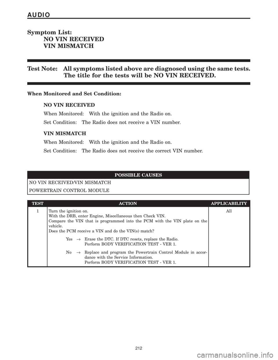
Symptom List:
NO VIN RECEIVED
VIN MISMATCH
Test Note: All symptoms listed above are diagnosed using the same tests.
The title for the tests will be NO VIN RECEIVED.
When Monitored and Set Condition:
NO VIN RECEIVED
When Monitored: With the ignition and the Radio on.
Set Condition: The Radio does not receive a VIN number.
VIN MISMATCH
When Monitored: With the ignition and the Radio on.
Set Condition: The Radio does not receive the correct VIN number.
POSSIBLE CAUSES
NO VIN RECEIVED/VIN MISMATCH
POWERTRAIN CONTROL MODULE
TEST ACTION APPLICABILITY
1 Turn the ignition on.
With the DRB, enter Engine, Miscellaneous then Check VIN.
Compare the VIN that is programmed into the PCM with the VIN plate on the
vehicle.
Does the PCM receive a VIN and do the VIN(s) match?All
Ye s®Erase the DTC. If DTC resets, replace the Radio.
Perform BODY VERIFICATION TEST - VER 1.
No®Replace and program the Powertrain Control Module in accor-
dance with the Service Information.
Perform BODY VERIFICATION TEST - VER 1.
212
AUDIO
Page 246 of 4284
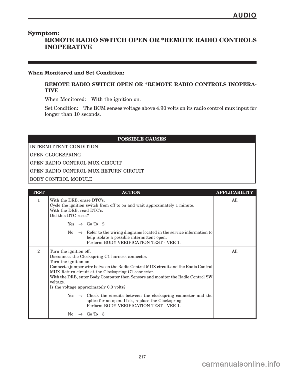
Symptom:
REMOTE RADIO SWITCH OPEN OR *REMOTE RADIO CONTROLS
INOPERATIVE
When Monitored and Set Condition:
REMOTE RADIO SWITCH OPEN OR *REMOTE RADIO CONTROLS INOPERA-
TIVE
When Monitored: With the ignition on.
Set Condition: The BCM senses voltage above 4.90 volts on its radio control mux input for
longer than 10 seconds.
POSSIBLE CAUSES
INTERMITTENT CONDITION
OPEN CLOCKSPRING
OPEN RADIO CONTROL MUX CIRCUIT
OPEN RADIO CONTROL MUX RETURN CIRCUIT
BODY CONTROL MODULE
TEST ACTION APPLICABILITY
1 With the DRB, erase DTC's.
Cycle the ignition switch from off to on and wait approximately 1 minute.
With the DRB, read DTC's.
Did this DTC reset?All
Ye s®Go To 2
No®Refer to the wiring diagrams located in the service information to
help isolate a possible intermittent open.
Perform BODY VERIFICATION TEST - VER 1.
2 Turn the ignition off.
Disconnect the Clockspring C1 harness connector.
Turn the ignition on.
Connect a jumper wire between the Radio Control MUX circuit and the Radio Control
MUX Return circuit at the Clockspring C1 connector.
With the DRB, enter Body Computer then Sensors and monitor the Radio Control SW
voltage.
Is the voltage approximately 0.0 volts?All
Ye s®Check the circuits between the clockspring connector and the
splice for an open. If ok, replace the Clockspring.
Perform BODY VERIFICATION TEST - VER 1.
No®Go To 3
217
AUDIO
Page 248 of 4284
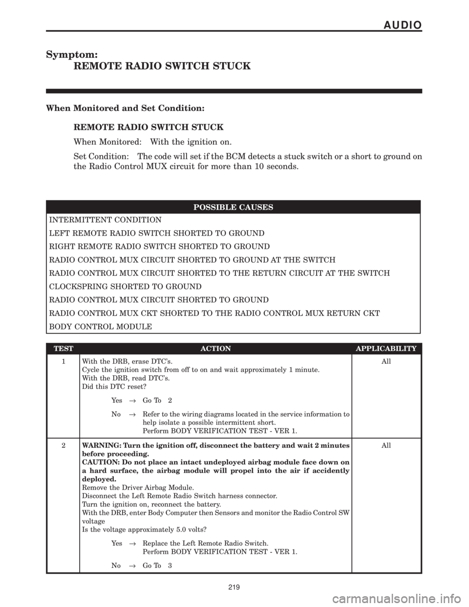
Symptom:
REMOTE RADIO SWITCH STUCK
When Monitored and Set Condition:
REMOTE RADIO SWITCH STUCK
When Monitored: With the ignition on.
Set Condition: The code will set if the BCM detects a stuck switch or a short to ground on
the Radio Control MUX circuit for more than 10 seconds.
POSSIBLE CAUSES
INTERMITTENT CONDITION
LEFT REMOTE RADIO SWITCH SHORTED TO GROUND
RIGHT REMOTE RADIO SWITCH SHORTED TO GROUND
RADIO CONTROL MUX CIRCUIT SHORTED TO GROUND AT THE SWITCH
RADIO CONTROL MUX CIRCUIT SHORTED TO THE RETURN CIRCUIT AT THE SWITCH
CLOCKSPRING SHORTED TO GROUND
RADIO CONTROL MUX CIRCUIT SHORTED TO GROUND
RADIO CONTROL MUX CKT SHORTED TO THE RADIO CONTROL MUX RETURN CKT
BODY CONTROL MODULE
TEST ACTION APPLICABILITY
1 With the DRB, erase DTC's.
Cycle the ignition switch from off to on and wait approximately 1 minute.
With the DRB, read DTC's.
Did this DTC reset?All
Ye s®Go To 2
No®Refer to the wiring diagrams located in the service information to
help isolate a possible intermittent short.
Perform BODY VERIFICATION TEST - VER 1.
2WARNING: Turn the ignition off, disconnect the battery and wait 2 minutes
before proceeding.
CAUTION: Do not place an intact undeployed airbag module face down on
a hard surface, the airbag module will propel into the air if accidently
deployed.
Remove the Driver Airbag Module.
Disconnect the Left Remote Radio Switch harness connector.
Turn the ignition on, reconnect the battery.
With the DRB, enter Body Computer then Sensors and monitor the Radio Control SW
voltage
Is the voltage approximately 5.0 volts?All
Ye s®Replace the Left Remote Radio Switch.
Perform BODY VERIFICATION TEST - VER 1.
No®Go To 3
219
AUDIO
Page 288 of 4284

TEST ACTION APPLICABILITY
3CAUTION: The work area ambient temperature must be above 15.6ÉC (60ÉF)
to test A/C system operation.
Turn the ignition on.
With the DRBIIIt, check the PCM/ECM for DTCs.
Are any DTCs present?All
Ye s®Refer to the Powertrain Diagnostic information for the related
symptom(s). After the repair is complete, with the DRBIIIt, erase
the DTC(s). Cycle the ignition switch. With the DRBIIIt, reset the
ATC. With the DRBIIIt, accuate the Cooldown Test.
Perform BODY VERIFICATION TEST - VER 1.
No®Go To 4
4 Turn the ignition off.
Disconnect the Evaporator Temperature Sensor harness connector.
Turn the ignition on.
With the DRBIIItin Sensor Display, read the Evaporator Temperature Sensor
voltage.
Is the voltage above 4.9 volts?All
Ye s®Go To 5
No®Go To 6
5 Turn the ignition off.
Disconnect the Evaporator Temperature Sensor harness connector.
Connect a jumper wire between the Evaporator Temperature Sensor Signal circuit
and the Sensor Ground circuit at the Evaporator Temperature Sensor harness
connector.
Turn the ignition on.
With the DRBIIItin Sensor Display, read the Evaporator Temperature Sensor
voltage.
Is the voltage 0.0 volts?All
Ye s®Replace the Evaporator Temperature Sensor in accordance with
the Service Information. After the repair is complete, with the
DRBIIIt, reset the ATC. With the DRBIIIt, accuate the Cooldown
Test.
Perform BODY VERIFICATION TEST - VER 1.
No®Go To 6
6NOTE: Ensure that the voltmeter leads meet the terminals in the connector
and that there is good terminal to wire connection.
NOTE: Ensure the voltmeter leads are connected for positive polarity.
Back probe the Sensor Ground circuit between the Evaporator Temperature Sensor
harness connector and the ATC harness connector.
Turn the ignition on.
Is the voltage below 0.10 volt?All
Ye s®Go To 7
No®Repair the high resistance in the Sensor Ground circuit. After the
repair is complete, with the DRBIIIt, reset the ATC. With the
DRBIIIt, accuate the Cooldown Test.
Perform BODY VERIFICATION TEST - VER 1.
259
AUTOMATIC TEMPERATURE CONTROL
INVALID CONDITIONS FOR COOLDOWN TEST, EVAP TEMPERATURE
TOO LOW Ð
Continued
Page 327 of 4284
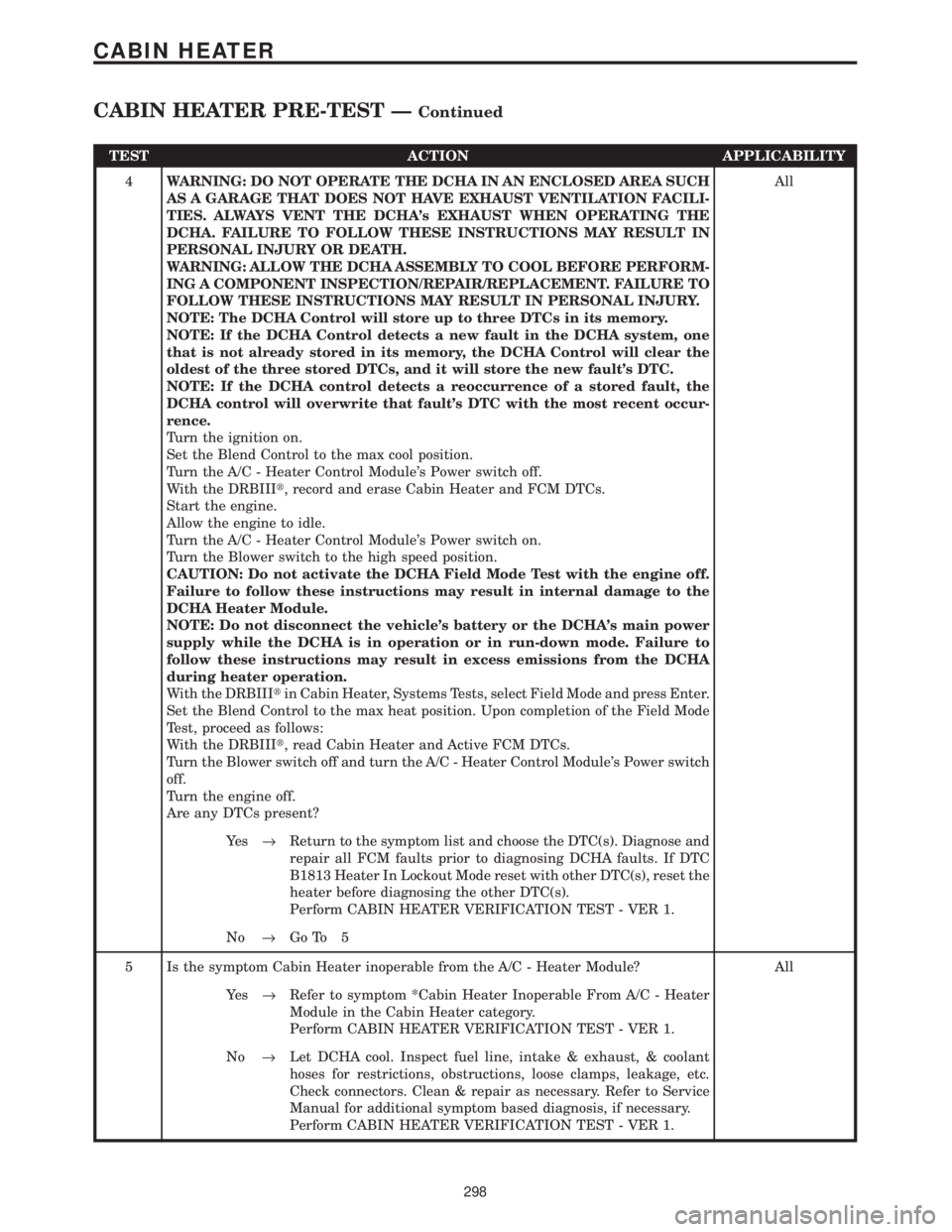
TEST ACTION APPLICABILITY
4WARNING: DO NOT OPERATE THE DCHA IN AN ENCLOSED AREA SUCH
AS A GARAGE THAT DOES NOT HAVE EXHAUST VENTILATION FACILI-
TIES. ALWAYS VENT THE DCHA's EXHAUST WHEN OPERATING THE
DCHA. FAILURE TO FOLLOW THESE INSTRUCTIONS MAY RESULT IN
PERSONAL INJURY OR DEATH.
WARNING: ALLOW THE DCHA ASSEMBLY TO COOL BEFORE PERFORM-
ING A COMPONENT INSPECTION/REPAIR/REPLACEMENT. FAILURE TO
FOLLOW THESE INSTRUCTIONS MAY RESULT IN PERSONAL INJURY.
NOTE: The DCHA Control will store up to three DTCs in its memory.
NOTE: If the DCHA Control detects a new fault in the DCHA system, one
that is not already stored in its memory, the DCHA Control will clear the
oldest of the three stored DTCs, and it will store the new fault's DTC.
NOTE: If the DCHA control detects a reoccurrence of a stored fault, the
DCHA control will overwrite that fault's DTC with the most recent occur-
rence.
Turn the ignition on.
Set the Blend Control to the max cool position.
Turn the A/C - Heater Control Module's Power switch off.
With the DRBIIIt, record and erase Cabin Heater and FCM DTCs.
Start the engine.
Allow the engine to idle.
Turn the A/C - Heater Control Module's Power switch on.
Turn the Blower switch to the high speed position.
CAUTION: Do not activate the DCHA Field Mode Test with the engine off.
Failure to follow these instructions may result in internal damage to the
DCHA Heater Module.
NOTE: Do not disconnect the vehicle's battery or the DCHA's main power
supply while the DCHA is in operation or in run-down mode. Failure to
follow these instructions may result in excess emissions from the DCHA
during heater operation.
With the DRBIIItin Cabin Heater, Systems Tests, select Field Mode and press Enter.
Set the Blend Control to the max heat position. Upon completion of the Field Mode
Test, proceed as follows:
With the DRBIIIt, read Cabin Heater and Active FCM DTCs.
Turn the Blower switch off and turn the A/C - Heater Control Module's Power switch
off.
Turn the engine off.
Are any DTCs present?All
Ye s®Return to the symptom list and choose the DTC(s). Diagnose and
repair all FCM faults prior to diagnosing DCHA faults. If DTC
B1813 Heater In Lockout Mode reset with other DTC(s), reset the
heater before diagnosing the other DTC(s).
Perform CABIN HEATER VERIFICATION TEST - VER 1.
No®Go To 5
5 Is the symptom Cabin Heater inoperable from the A/C - Heater Module? All
Ye s®Refer to symptom *Cabin Heater Inoperable From A/C - Heater
Module in the Cabin Heater category.
Perform CABIN HEATER VERIFICATION TEST - VER 1.
No®Let DCHA cool. Inspect fuel line, intake & exhaust, & coolant
hoses for restrictions, obstructions, loose clamps, leakage, etc.
Check connectors. Clean & repair as necessary. Refer to Service
Manual for additional symptom based diagnosis, if necessary.
Perform CABIN HEATER VERIFICATION TEST - VER 1.
298
CABIN HEATER
CABIN HEATER PRE-TEST ÐContinued
Page 341 of 4284
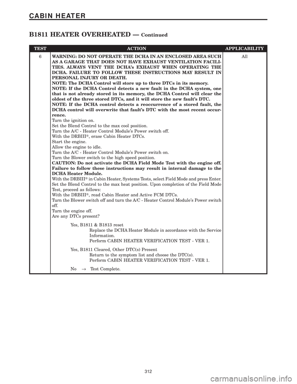
TEST ACTION APPLICABILITY
6WARNING: DO NOT OPERATE THE DCHA IN AN ENCLOSED AREA SUCH
AS A GARAGE THAT DOES NOT HAVE EXHAUST VENTILATION FACILI-
TIES. ALWAYS VENT THE DCHA's EXHAUST WHEN OPERATING THE
DCHA. FAILURE TO FOLLOW THESE INSTRUCTIONS MAY RESULT IN
PERSONAL INJURY OR DEATH.
NOTE: The DCHA Control will store up to three DTCs in its memory.
NOTE: If the DCHA Control detects a new fault in the DCHA system, one
that is not already stored in its memory, the DCHA Control will clear the
oldest of the three stored DTCs, and it will store the new fault's DTC.
NOTE: If the DCHA control detects a reoccurrence of a stored fault, the
DCHA control will overwrite that fault's DTC with the most recent occur-
rence.
Turn the ignition on.
Set the Blend Control to the max cool position.
Turn the A/C - Heater Control Module's Power switch off.
With the DRBIIIt, erase Cabin Heater DTCs.
Start the engine.
Allow the engine to idle.
Turn the A/C - Heater Control Module's Power switch on.
Turn the Blower switch to the high speed position.
CAUTION: Do not activate the DCHA Field Mode Test with the engine off.
Failure to follow these instructions may result in internal damage to the
DCHA Heater Module.
With the DRBIIItin Cabin Heater, Systems Tests, select Field Mode and press Enter.
Set the Blend Control to the max heat position. Upon completion of the Field Mode
Test, proceed as follows:
With the DRBIIIt, read Cabin Heater and Active FCM DTCs.
Turn the Blower switch off and turn the A/C - Heater Control Module's Power switch
off.
Turn the engine off.
Are any DTCs present?All
Yes, B1811 & B1813 reset
Replace the DCHA Heater Module in accordance with the Service
Information.
Perform CABIN HEATER VERIFICATION TEST - VER 1.
Yes, B1811 Cleared, Other DTC(s) Present
Return to the symptom list and choose the DTC(s).
Perform CABIN HEATER VERIFICATION TEST - VER 1.
No®Test Complete.
312
CABIN HEATER
B1811 HEATER OVERHEATED ÐContinued
Page 343 of 4284
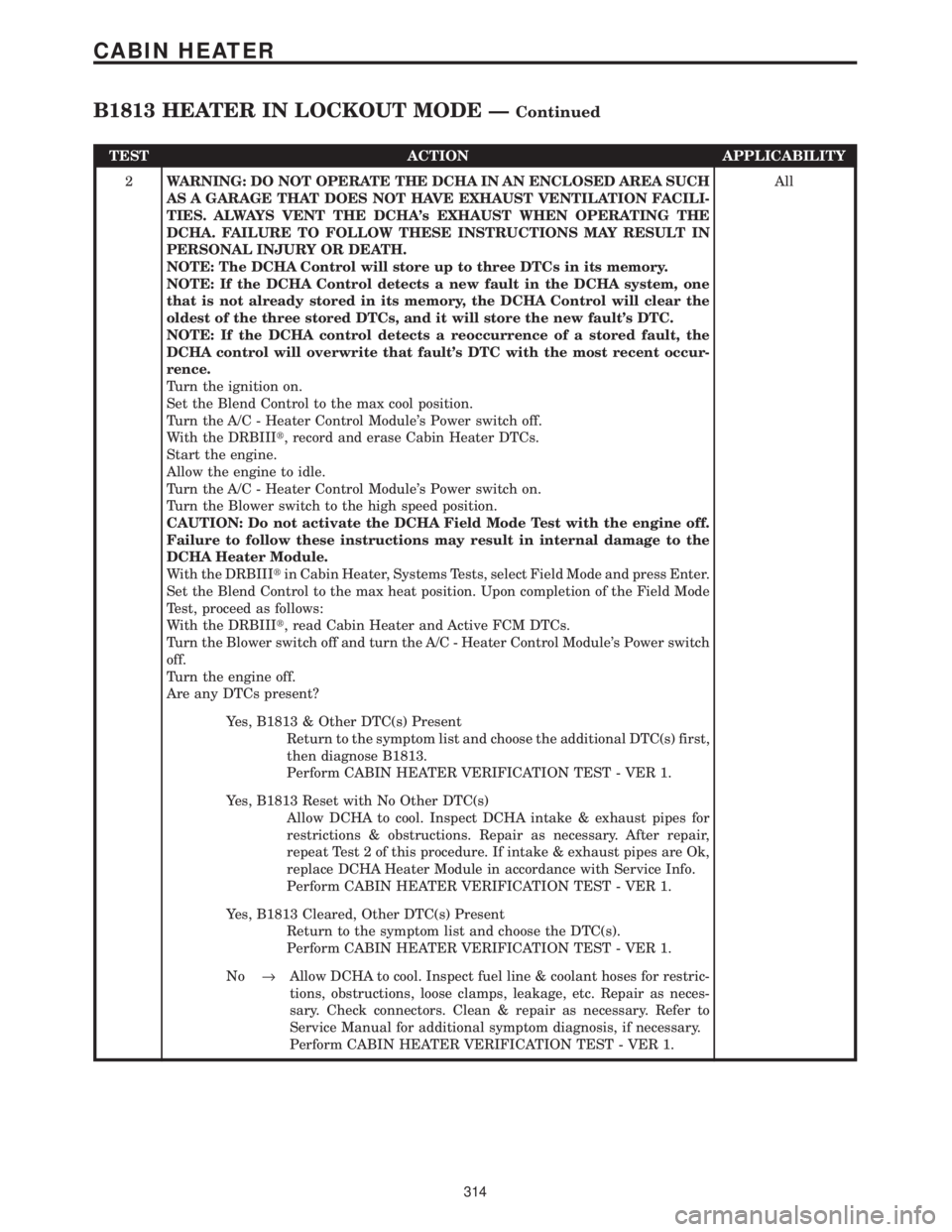
TEST ACTION APPLICABILITY
2WARNING: DO NOT OPERATE THE DCHA IN AN ENCLOSED AREA SUCH
AS A GARAGE THAT DOES NOT HAVE EXHAUST VENTILATION FACILI-
TIES. ALWAYS VENT THE DCHA's EXHAUST WHEN OPERATING THE
DCHA. FAILURE TO FOLLOW THESE INSTRUCTIONS MAY RESULT IN
PERSONAL INJURY OR DEATH.
NOTE: The DCHA Control will store up to three DTCs in its memory.
NOTE: If the DCHA Control detects a new fault in the DCHA system, one
that is not already stored in its memory, the DCHA Control will clear the
oldest of the three stored DTCs, and it will store the new fault's DTC.
NOTE: If the DCHA control detects a reoccurrence of a stored fault, the
DCHA control will overwrite that fault's DTC with the most recent occur-
rence.
Turn the ignition on.
Set the Blend Control to the max cool position.
Turn the A/C - Heater Control Module's Power switch off.
With the DRBIIIt, record and erase Cabin Heater DTCs.
Start the engine.
Allow the engine to idle.
Turn the A/C - Heater Control Module's Power switch on.
Turn the Blower switch to the high speed position.
CAUTION: Do not activate the DCHA Field Mode Test with the engine off.
Failure to follow these instructions may result in internal damage to the
DCHA Heater Module.
With the DRBIIItin Cabin Heater, Systems Tests, select Field Mode and press Enter.
Set the Blend Control to the max heat position. Upon completion of the Field Mode
Test, proceed as follows:
With the DRBIIIt, read Cabin Heater and Active FCM DTCs.
Turn the Blower switch off and turn the A/C - Heater Control Module's Power switch
off.
Turn the engine off.
Are any DTCs present?All
Yes, B1813 & Other DTC(s) Present
Return to the symptom list and choose the additional DTC(s) first,
then diagnose B1813.
Perform CABIN HEATER VERIFICATION TEST - VER 1.
Yes, B1813 Reset with No Other DTC(s)
Allow DCHA to cool. Inspect DCHA intake & exhaust pipes for
restrictions & obstructions. Repair as necessary. After repair,
repeat Test 2 of this procedure. If intake & exhaust pipes are Ok,
replace DCHA Heater Module in accordance with Service Info.
Perform CABIN HEATER VERIFICATION TEST - VER 1.
Yes, B1813 Cleared, Other DTC(s) Present
Return to the symptom list and choose the DTC(s).
Perform CABIN HEATER VERIFICATION TEST - VER 1.
No®Allow DCHA to cool. Inspect fuel line & coolant hoses for restric-
tions, obstructions, loose clamps, leakage, etc. Repair as neces-
sary. Check connectors. Clean & repair as necessary. Refer to
Service Manual for additional symptom diagnosis, if necessary.
Perform CABIN HEATER VERIFICATION TEST - VER 1.
314
CABIN HEATER
B1813 HEATER IN LOCKOUT MODE ÐContinued
Page 376 of 4284

Symptom:
FCM, PCM COMMUNICATION FAULT
When Monitored and Set Condition:
FCM, PCM COMMUNICATION FAULT
When Monitored: With the ignition in run, and the IOD fuse installed.
Set Condition: The FCM does not receive any messages from the PCM for at least 5
seconds.
POSSIBLE CAUSES
PCM COMMUNICATION FAULT
ATTEMPT TO COMMUNICATE WITH THE PCM
PCI BUS CIRCUIT OPEN
POWERTRAIN CONTROL MODULE
TEST ACTION APPLICABILITY
1 Turn the ignition on.
With the DRB, enter Instrument Cluster, System Tests then PCM Monitor.
Does the DRB display: PCM is active on BUS?All
Ye s®Erase the DTC, if DTC resets, replace the Front Control Module.
Perform BODY VERIFICATION TEST - VER 1.
No®Go To 2
2 Turn the ignition on.
With the DRB, attempt to communicate with the PCM.
Was the DRB able to communicate with the PCM?All
Ye s®Go To 3
No®Refer to the communication category and perform the appropriate
symptom.
Perform BODY VERIFICATION TEST - VER 1.
3 Turn the ignition off.
Disconnect the PCM C2 harness connector.
Connect the diagnostic junction port tester #8339 to the diagnostic junction port.
Note: Do not connect the tester to the DRB.
Measure the resistance of the PCI Bus circuit between the diagnostic junction port
tester and the PCM C2 connector.
Is the resistance below 5.0 ohms?All
Ye s®Replace and program the Powertrain Control Module in accor-
dance with the Service Information.
Perform BODY VERIFICATION TEST - VER 1.
No®Repair the PCI Bus circuit for an open.
Perform BODY VERIFICATION TEST - VER 1.
347
COMMUNICATION