2001 CHRYSLER VOYAGER service reset
[x] Cancel search: service resetPage 3173 of 4284
INSTALLATION
NOTE: If transaxle assembly has been replaced or
overhauled (clutch and/or seal replacement), it is
necessary to perfrom the TCM Quick Learn proce-
dure. (Refer to 8 - ELECTRICAL/ELECTRONIC CON-
TROL MODULES/TRANSMISSION CONTROL
MODULE - STANDARD PROCEDURE)
NOTE: If torque converter assembly has been
replaced, it is necessary to reset the TCC Break-In
Strategy. (Refer to 8 - ELECTRICAL/ELECTRONIC
CONTROL MODULES/TRANSMISSION CONTROL
MODULE - STANDARD PROCEDURE)
(1) Using a transmission jack and a helper, posi-
tion transaxle assembly to engine. Install and torque
bolts to 95 N´m (70 ft. lbs.).
(2) Install upper mount assembly to transaxle and
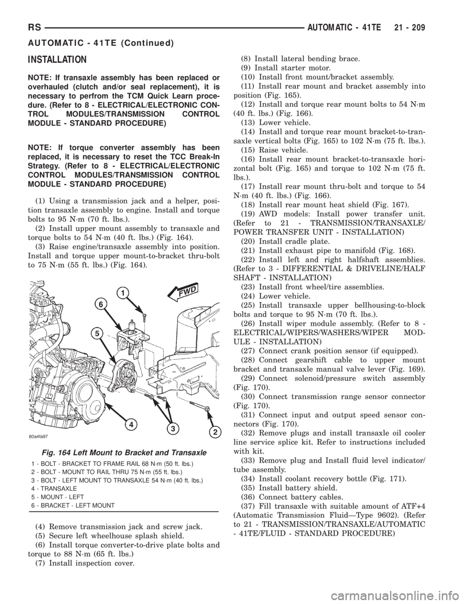
torque bolts to 54 N´m (40 ft. lbs.) (Fig. 164).
(3) Raise engine/transaxle assembly into position.
Install and torque upper mount-to-bracket thru-bolt
to 75 N´m (55 ft. lbs.) (Fig. 164).
(4) Remove transmission jack and screw jack.
(5) Secure left wheelhouse splash shield.
(6) Install torque converter-to-drive plate bolts and
torque to 88 N´m (65 ft. lbs.)
(7) Install inspection cover.(8) Install lateral bending brace.
(9) Install starter motor.
(10) Install front mount/bracket assembly.
(11) Install rear mount and bracket assembly into
position (Fig. 165).
(12) Install and torque rear mount bolts to 54 N´m
(40 ft. lbs.) (Fig. 166).
(13) Lower vehicle.
(14) Install and torque rear mount bracket-to-tran-
saxle vertical bolts (Fig. 165) to 102 N´m (75 ft. lbs.).
(15) Raise vehicle.
(16) Install rear mount bracket-to-transaxle hori-
zontal bolt (Fig. 165) and torque to 102 N´m (75 ft.
lbs.).
(17) Install rear mount thru-bolt and torque to 54
N´m (40 ft. lbs.) (Fig. 166).
(18) Install rear mount heat shield (Fig. 167).
(19) AWD models: Install power transfer unit.
(Refer to 21 - TRANSMISSION/TRANSAXLE/
POWER TRANSFER UNIT - INSTALLATION)
(20) Install cradle plate.
(21) Install exhaust pipe to manifold (Fig. 168).
(22) Install left and right halfshaft assemblies.
(Refer to 3 - DIFFERENTIAL & DRIVELINE/HALF
SHAFT - INSTALLATION)
(23) Install front wheel/tire assemblies.
(24) Lower vehicle.
(25) Install transaxle upper bellhousing-to-block
bolts and torque to 95 N´m (70 ft. lbs.).
(26) Install wiper module assembly. (Refer to 8 -
ELECTRICAL/WIPERS/WASHERS/WIPER MOD-
ULE - INSTALLATION)
(27) Connect crank position sensor (if equipped).
(28) Connect gearshift cable to upper mount
bracket and transaxle manual valve lever (Fig. 169).
(29) Connect solenoid/pressure switch assembly
(Fig. 170).
(30) Connect transmission range sensor connector
(Fig. 170).
(31) Connect input and output speed sensor con-
nectors (Fig. 170).
(32) Remove plugs and install transaxle oil cooler
line service splice kit. Refer to instructions included
with kit.
(33) Remove plug and Install fluid level indicator/
tube assembly.
(34) Install coolant recovery bottle (Fig. 171).
(35) Install battery shield.
(36) Connect battery cables.
(37) Fill transaxle with suitable amount of ATF+4
(Automatic Transmission FluidÐType 9602). (Refer
to 21 - TRANSMISSION/TRANSAXLE/AUTOMATIC
- 41TE/FLUID - STANDARD PROCEDURE)
Fig. 164 Left Mount to Bracket and Transaxle
1 - BOLT - BRACKET TO FRAME RAIL 68 N´m (50 ft. lbs.)
2 - BOLT - MOUNT TO RAIL THRU 75 N´m (55 ft. lbs.)
3 - BOLT - LEFT MOUNT TO TRANSAXLE 54 N´m (40 ft. lbs.)
4 - TRANSAXLE
5 - MOUNT - LEFT
6 - BRACKET - LEFT MOUNT
RSAUTOMATIC - 41TE21 - 209
AUTOMATIC - 41TE (Continued)
Page 3251 of 4284
TRANSMISSION CONTROL
RELAY
DESCRIPTION
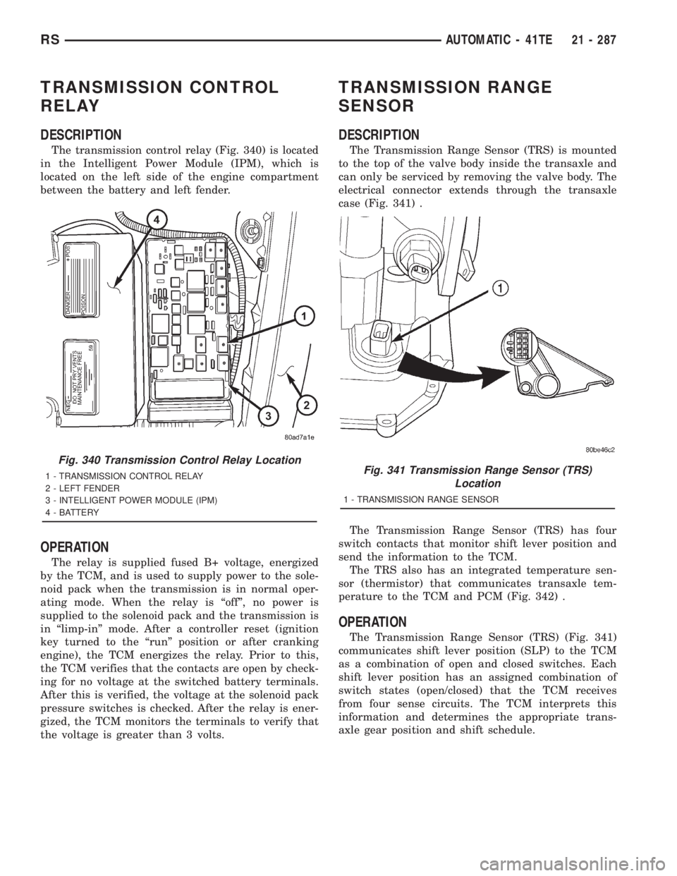
The transmission control relay (Fig. 340) is located
in the Intelligent Power Module (IPM), which is
located on the left side of the engine compartment
between the battery and left fender.
OPERATION
The relay is supplied fused B+ voltage, energized
by the TCM, and is used to supply power to the sole-
noid pack when the transmission is in normal oper-
ating mode. When the relay is ªoffº, no power is
supplied to the solenoid pack and the transmission is
in ªlimp-inº mode. After a controller reset (ignition
key turned to the ªrunº position or after cranking
engine), the TCM energizes the relay. Prior to this,
the TCM verifies that the contacts are open by check-
ing for no voltage at the switched battery terminals.
After this is verified, the voltage at the solenoid pack
pressure switches is checked. After the relay is ener-
gized, the TCM monitors the terminals to verify that
the voltage is greater than 3 volts.
TRANSMISSION RANGE
SENSOR
DESCRIPTION
The Transmission Range Sensor (TRS) is mounted
to the top of the valve body inside the transaxle and
can only be serviced by removing the valve body. The
electrical connector extends through the transaxle
case (Fig. 341) .
The Transmission Range Sensor (TRS) has four
switch contacts that monitor shift lever position and
send the information to the TCM.
The TRS also has an integrated temperature sen-
sor (thermistor) that communicates transaxle tem-
perature to the TCM and PCM (Fig. 342) .
OPERATION
The Transmission Range Sensor (TRS) (Fig. 341)
communicates shift lever position (SLP) to the TCM
as a combination of open and closed switches. Each
shift lever position has an assigned combination of
switch states (open/closed) that the TCM receives
from four sense circuits. The TCM interprets this
information and determines the appropriate trans-
axle gear position and shift schedule.
Fig. 340 Transmission Control Relay Location
1 - TRANSMISSION CONTROL RELAY
2 - LEFT FENDER
3 - INTELLIGENT POWER MODULE (IPM)
4 - BATTERYFig. 341 Transmission Range Sensor (TRS)
Location
1 - TRANSMISSION RANGE SENSOR
RSAUTOMATIC - 41TE21 - 287
Page 3802 of 4284
powertrain control module checks that circuit or
function. Procedures in this manual verify if the
DTC is a hard code at the beginning of each test.
When it is not a hard code, an intermittent test
must be performed.
DTC's that are for Euro Stage III OBD monitors
will not set with just the ignition key on. Comparing
these to non-emission DTC's, they will seem like an
intermittent. These DTC's require a set of parame-
ters to be performed (The DRBIIItpre-test screens
will help with this for MONITOR DTC's), this is
called a TRIP. All Euro Stage III OBD DTCs will be
set after one or in some cases two trip failures, and
the MIL will be turned on. These DTC's require
three successful, no failures, TRIPS to extinguish
the MIL, followed by 40 warm-up cycles to erase the
DTC.
3.3.2 INTERMITTENT CODE
A diagnostic trouble code that is not there every
time the PCM checks the circuit is an intermittent
DTC. Most intermittent DTC's are caused by wiring
or connector problems. Defects that come and go
like this are the most difficult to diagnose; they
must be looked for under specific conditions that
cause them. The following checks may assist you in
identifying a possible intermittent problem:
²Visually inspect related wire harness connectors.
Look for broken, bent, pushed out, or corroded
terminals.
²Visually inspect the related harnesses. Look for
chafed, pierced, or partially broken wire.
²Refer to any technical service bulletins that may
apply.
²Use the DRBIIItdata recorder or co-pilot.
3.3.3 DISTANCE SINCE MI SET
The Euro Stage III OBD directive requires that
the distance traveled by the vehicle while theMIis
activated must be available at any instant through
the serial port on the standard data link connector.
This feature works as follows:1. If the MI is illuminated due to a fault, the
distance count is updated (i.e. it is counting).
2. If there is a9stale9MI fault (i.e. the fault is still
frozen in memory but the MI has heen extin-
guished due to 3 good trips), the distance count is
held (i.e. frozen).
3. If the distance count is being held due to (Item
2.) and the fault is cleared, the distance is
cleared (set to zero).
4. If the distance count is being held due to (Item
2.) and another MI occurs, the distance count is
reset (to 0) and begins updating anew.
5. If a fault occurs while the MI is already illumi-
nated due to a previous fault (the distance count
is updating), then the distance count continues
to update w/out interruption.
6. If the MI is flashing due to activate misfire and
there is and9active9fault (i.e. matured fault for
which 3 good trips have not occurred), the dis-
tance count behaves as the MI in ON.
7. If the MI is flashing due to active misfire and
there is no9active9fault (i.e. the MI is flashing
for a 1 malf.), the distance count behaves as if
the MI is off (because it is not yet a matured
fault).
8. The distance count is cleared whenever the fault
is cleared. (Via 40 warm up cycles, or via scan
tool).
3.3.4 HANDLING NO DTC PROBLEMS
Symptom checks cannot be used properly unless
the driveability problem characteristic actually
happens while the vehicle is being tested.
Select the symptom that most accurately de-
scribes the vehicle's driveability problem and then
perform the test routine that pertains to this symp-
tom. Perform each routine test in sequence until the
problem is found. For definitions, see Section 6.0
Glossary Of Terms.
SYMPTOM DIAGNOSTIC TEST
HARD START CHECKING THE FUEL PRESSURE
CHECKING THE ECT SENSOR
CHECKING THROTTLE POSITION SENSOR
CHECKING MAP SENSOR
CHECKING IDLE AIR CONTROL MOTOR OPERATION
CHECKING EGR SYSTEM
CHECKING IAT SENSOR
8
GENERAL INFORMATION
Page 3819 of 4284
TEST ACTION APPLICABILITY
5 Turn the ignition on.
With the DRB III, display the VIN that is programmed in the PCM.
Was the correct VIN programmed into the PCM?All
Ye s®Go To 6
No®Replace and program the Powertrain Control Module in accor-
dance with the Service Information.
Perform SKIS VERIFICATION TEST.
6 Turn the ignition off.
Replace and program the Sentry Key Immobilizer Module in accordance with the
Service Information.
Turn the ignition on.
With the DRB III, erase all SKIM and PCM DTCs.
Attempt to start and idle the engine.
With the DRB III, read the PCM DTCs.
Does the DRB III display this code?All
Ye s®Replace and program the Powertrain Control Module in accor-
dance with the Service Information.
Perform SKIS VERIFICATION TEST.
No®Test Complete.
7NOTE: This DTC could have been set if the SKIM harness connector was
disconnected, or if the SKIM was replaced recently.
NOTE: All keys that the customer uses for this vehicle must be tested to
verify they are operating properly.
Turn the ignition on.
Verify the correct VIN is programmed into the PCM and SKIM.
Turn the ignition off.
With the next customer key turn the ignition key on and crank the engine to start.
With the DRB III, read the PCM DTCs. Look for P1685
Is the Starts Since Set counter for DTC P1685 displayed and equal to 0?All
Ye s®Replace the Ignition Key.
Perform SKIS VERIFICATION TEST.
No®Test Complete.
NOTE: If this DTC cannot be reset, it could have been an actual theft
attempt.
25
COMMUNICATION
P1685-WRONG OR INVALID KEY MSG RECEIVED FROM SKIM Ð
Continued
Page 3822 of 4284
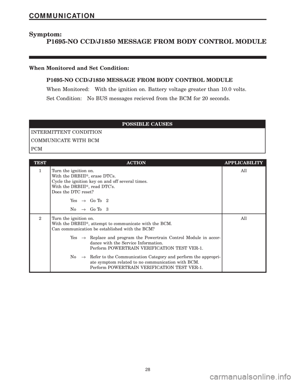
Symptom:
P1695-NO CCD/J1850 MESSAGE FROM BODY CONTROL MODULE
When Monitored and Set Condition:
P1695-NO CCD/J1850 MESSAGE FROM BODY CONTROL MODULE
When Monitored: With the ignition on. Battery voltage greater than 10.0 volts.
Set Condition: No BUS messages recieved from the BCM for 20 seconds.
POSSIBLE CAUSES
INTERMITTENT CONDITION
COMMUNICATE WITH BCM
PCM
TEST ACTION APPLICABILITY
1 Turn the ignition on.
With the DRBIIIt, erase DTCs.
Cycle the ignition key on and off several times.
With the DRBIIIt, read DTC's.
Does the DTC reset?All
Ye s®Go To 2
No®Go To 3
2 Turn the ignition on.
With the DRBIIIt, attempt to communicate with the BCM.
Can communication be established with the BCM?All
Ye s®Replace and program the Powertrain Control Module in accor-
dance with the Service Information.
Perform POWERTRAIN VERIFICATION TEST VER-1.
No®Refer to the Communication Category and perform the appropri-
ate symptom related to no communication with BCM.
Perform POWERTRAIN VERIFICATION TEST VER-1.
28
COMMUNICATION
Page 3826 of 4284
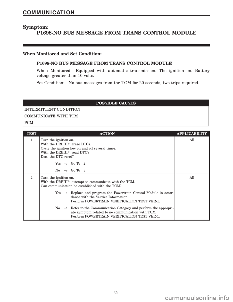
Symptom:
P1698-NO BUS MESSAGE FROM TRANS CONTROL MODULE
When Monitored and Set Condition:
P1698-NO BUS MESSAGE FROM TRANS CONTROL MODULE
When Monitored: Equipped with automatic transmission. The ignition on. Battery
voltage greater than 10 volts.
Set Condition: No bus messages from the TCM for 20 seconds, two trips required.
POSSIBLE CAUSES
INTERMITTENT CONDITION
COMMUNICATE WITH TCM
PCM
TEST ACTION APPLICABILITY
1 Turn the ignition on.
With the DRBIIIt, erase DTCs.
Cycle the ignition key on and off several times.
With the DRBIIIt, read DTC's.
Does the DTC reset?All
Ye s®Go To 2
No®Go To 3
2 Turn the ignition on.
With the DRBIIIt, attempt to communicate with the TCM.
Can communication be established with the TCM?All
Ye s®Replace and program the Powertrain Control Module in accor-
dance with the Service Information.
Perform POWERTRAIN VERIFICATION TEST VER-1.
No®Refer to the Communication Category and perform the appropri-
ate symptom related to no communication with TCM.
Perform POWERTRAIN VERIFICATION TEST VER-1.
32
COMMUNICATION
Page 3993 of 4284
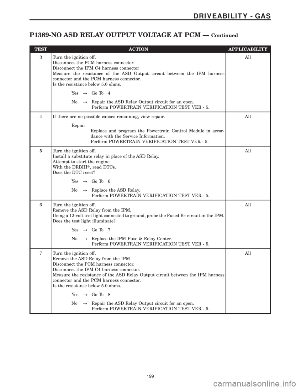
TEST ACTION APPLICABILITY
3 Turn the ignition off.
Disconnect the PCM harness connector.
Disconnect the IPM C4 harness connector
Measure the resistance of the ASD Output circuit between the IPM harness
connector and the PCM harness connector.
Is the resistance below 5.0 ohms.All
Ye s®Go To 4
No®Repair the ASD Relay Output circuit for an open.
Perform POWERTRAIN VERIFICATION TEST VER - 5.
4 If there are no possible causes remaining, view repair. All
Repair
Replace and program the Powertrain Control Module in accor-
dance with the Service Information.
Perform POWERTRAIN VERIFICATION TEST VER - 5.
5 Turn the ignition off.
Install a substitute relay in place of the ASD Relay.
Attempt to start the engine.
With the DRBIIIt, read DTCs.
Does the DTC reset?All
Ye s®Go To 6
No®Replace the ASD Relay.
Perform POWERTRAIN VERIFICATION TEST VER - 5.
6 Turn the ignition off.
Remove the ASD Relay from the IPM.
Using a 12-volt test light connected to ground, probe the Fused B+ circuit in the IPM.
Does the test light illuminate?All
Ye s®Go To 7
No®Replace the IPM Fuse & Relay Center.
Perform POWERTRAIN VERIFICATION TEST VER - 5.
7 Turn the ignition off.
Remove the ASD Relay from the IPM.
Disconnect the PCM harness connector.
Disconnect the IPM C4 harness connector.
Measure the resistance of the ASD Relay Output circuit between the IPM harness
connector and the PCM harness connector.
Is the resistance below 5.0 ohms.All
Ye s®Go To 8
No®Repair the ASD Relay Output circuit for an open.
Perform POWERTRAIN VERIFICATION TEST VER - 5.
199
DRIVEABILITY - GAS
P1389-NO ASD RELAY OUTPUT VOLTAGE AT PCM ÐContinued
Page 4015 of 4284
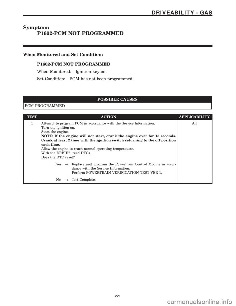
Symptom:
P1602-PCM NOT PROGRAMMED
When Monitored and Set Condition:
P1602-PCM NOT PROGRAMMED
When Monitored: Ignition key on.
Set Condition: PCM has not been programmed.
POSSIBLE CAUSES
PCM PROGRAMMED
TEST ACTION APPLICABILITY
1 Attempt to program PCM in accordance with the Service Information.
Turn the ignition on.
Start the engine.
NOTE: If the engine will not start, crank the engine over for 15 seconds.
Crank at least 2 time with the ignition switch returning to the off position
each time.
Allow the engine to reach normal operating temperature.
With the DRBIIIt, read DTCs.
Does the DTC reset?All
Ye s®Replace and program the Powertrain Control Module in accor-
dance with the Service Information.
Perform POWERTRAIN VERIFICATION TEST VER-1.
No®Test Complete.
221
DRIVEABILITY - GAS