2001 CHRYSLER VOYAGER sensor
[x] Cancel search: sensorPage 1908 of 4284
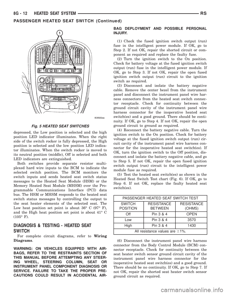
depressed, the Low position is selected and the high
position LED indicator illuminates. When the right
side of the switch rocker is fully depressed, the High
position is selected and the low position LED indica-
tor illuminates. When the switch rocker is moved to
its neutral position (middle), Off is selected and both
LED indicators are extinguished.
Both switches provide separate resistor multi-
plexed hard wire inputs to the BCM to indicate the
selected switch position. The BCM monitors the
switch inputs and sends heated seat switch status
messages to the Heated Seat Module (HSM) or the
Memory Heated Seat Module (MHSM) over the Pro-
grammable Communications Interface (PCI) data
bus. The HSM or MHSM responds to the heated seat
switch status messages by controlling the output to
the seat heater elements of the selected seat. The
Low heat position set point is about 36É C (97É F),
and the High heat position set point is about 41É C
(105É F).
DIAGNOSIS & TESTING - HEATED SEAT
SWITCH
For complete circuit diagrams, refer toWiring
Diagrams.
WARNING: ON VEHICLES EQUIPPED WITH AIR-
BAGS, REFER TO THE RESTRAINTS SECTION OF
THIS MANUAL BEFORE ATTEMPTING ANY STEER-
ING WHEEL, STEERING COLUMN, SEAT OR
INSTRUMENT PANEL COMPONENT DIAGNOSIS OR
SERVICE. FAILURE TO TAKE THE PROPER PRE-
CAUTIONS COULD RESULT IN ACCIDENTAL AIR-BAG DEPLOYMENT AND POSSIBLE PERSONAL
INJURY.
(1) Check the fused ignition switch output (run)
fuse in the intelligent power module. If OK, go to
Step 2. If not OK, repair the shorted circuit or com-
ponent as required and replace the faulty fuse.
(2) Turn the ignition switch to the On position.
Check for battery voltage at the fused ignition switch
output (run) fuse in the intelligent power module. If
OK, go to Step 3. If not OK, repair the open fused
ignition switch output (run) circuit to the ignition
switch as required.
(3) Disconnect and isolate the battery negative
cable. Remove the center bezel from the instrument
panel and disconnect the instrument panel wire har-
ness connectors from the heated seat switch connec-
tor receptacle. Check for continuity between the
ground circuit cavity of the instrument panel wire
harness connector for the inoperative heated seat
switch(es) and a good ground. There should be conti-
nuity. If OK, go to Step 4. If not OK, repair the open
ground circuit to ground as required.
(4) Reconnect the battery negative cable. Turn the
ignition switch to the On position. Check for battery
voltage at the fused ignition switch output (run) cir-
cuit cavity of the instrument panel wire harness con-
nector for the inoperative heated seat switch(es). If
OK, turn the ignition switch to the Off position, dis-
connect and isolate the battery negative cable, and go
to Step 5. If not OK, repair the open fused ignition
switch output (run) circuit to the intelligent power
module fuse as required.
(5) Test the heated seat switch(es) as shown in the
Heated Seat Switch Test chart (Fig. 6). If OK, go to
Step 6. If not OK, replace the faulty heated seat
switch(es).
PASSENGER HEATED SEAT SWITCH TEST
SWITCH
POSITIONRESISTANCE
BETWEENRESISTANCE
(OHMS)
Off Pin3&4OPEN
Low Pin3&43570
High Pin3&41430
All resistance values are61%.
(6) Disconnect the instrument panel wire harness
connector from the Body Control Module (BCM) con-
nector receptacle. Check for continuity between the
seat heater switch sensor ground circuit cavity of the
instrument panel wire harness connector for the
inoperative heated seat switch(es) and a good ground.
There should be no continuity. If OK, go to Step 7. If
not OK, repair the shorted seat heater switch sensor
ground circuit as required.
Fig. 5 HEATED SEAT SWITCHES
8G - 12 HEATED SEAT SYSTEMRS
PASSENGER HEATED SEAT SWITCH (Continued)
Page 1909 of 4284
(7) Check for continuity between the seat heater
switch sensor ground circuit cavities of the instru-
ment panel wire harness connector for the in opera-
tive heated seat switch and the instrument panel
wire harness connector for the BCM. There should be
continuity. If OK, go to Step 8. If not OK, repair the
open seat heater switch sensor ground circuit as
required.
(8) Check for continuity between the seat heater
switch mux circuit cavity of the instrument panel
wire harness connector for the inoperative heated
seat switch and a good ground. There should be no
continuity. If OK, go to Step 9. If not OK, repair the
shorted seat heater switch mux circuit as required.
(9) Check for continuity between the seat heater
switch mux circuit cavity of the instrument panel
wire harness connector for the inoperative heated
seat switch and the instrument panel wire harness
connector for the BCM. There should be continuity. If
OK, use a DRB IIItscan tool and the proper Diag-
nostic Procedures manual to test the BCM. If not
OK, repair the open seat heater switch mux circuit
as required.
REMOVAL
WARNING: ON VEHICLES EQUIPPED WITH AIR-
BAGS, REFER TO THE RESTRAINTS SECTION OF
THIS MANUAL BEFORE ATTEMPTING ANY STEER-
ING WHEEL, STEERING COLUMN, SEAT OR
INSTRUMENT PANEL COMPONENT DIAGNOSIS OR
SERVICE. FAILURE TO TAKE THE PROPER PRE-CAUTIONS COULD RESULT IN ACCIDENTAL AIR-
BAG DEPLOYMENT AND POSSIBLE PERSONAL
INJURY.
(1) Disconnect and isolate the battery negative
cable.
(2) Remove the instrument panel center bezel.
Refer toInstrument Panel Center Bezelin the
Body section for the procedure.
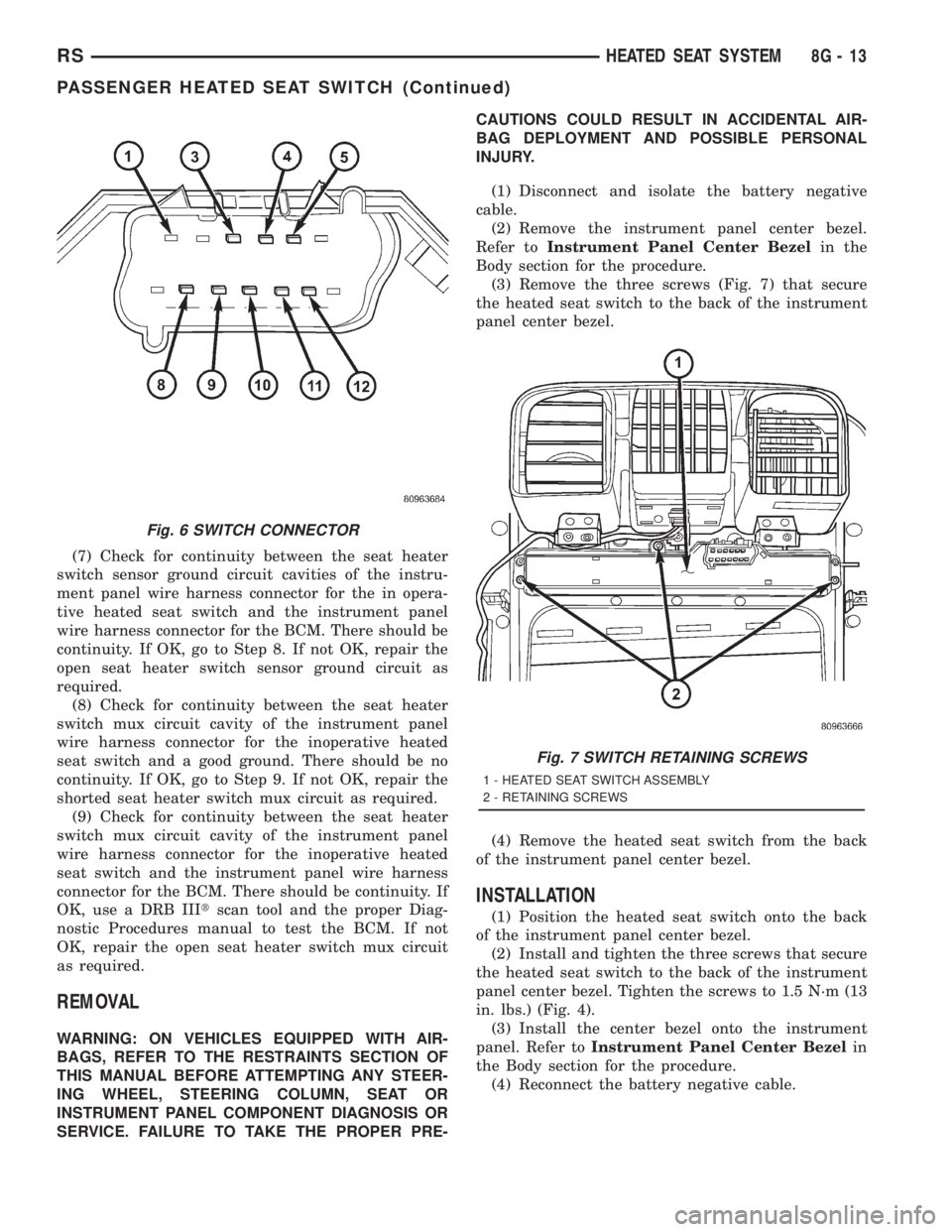
(3) Remove the three screws (Fig. 7) that secure
the heated seat switch to the back of the instrument
panel center bezel.
(4) Remove the heated seat switch from the back
of the instrument panel center bezel.
INSTALLATION
(1) Position the heated seat switch onto the back
of the instrument panel center bezel.
(2) Install and tighten the three screws that secure
the heated seat switch to the back of the instrument
panel center bezel. Tighten the screws to 1.5 N´m (13
in. lbs.) (Fig. 4).
(3) Install the center bezel onto the instrument
panel. Refer toInstrument Panel Center Bezelin
the Body section for the procedure.
(4) Reconnect the battery negative cable.
Fig. 6 SWITCH CONNECTOR
Fig. 7 SWITCH RETAINING SCREWS
1 - HEATED SEAT SWITCH ASSEMBLY
2 - RETAINING SCREWS
RSHEATED SEAT SYSTEM8G-13
PASSENGER HEATED SEAT SWITCH (Continued)
Page 1917 of 4284
IGNITION CONTROL
TABLE OF CONTENTS
page page
IGNITION CONTROL
DESCRIPTION............................1
OPERATION.............................1
SPECIFICATIONS.........................1
AUTO SHUT DOWN RELAY
DESCRIPTION............................3
OPERATION.............................3
CAMSHAFT POSITION SENSOR
DESCRIPTION............................3
OPERATION.............................3
REMOVAL...............................3
INSTALLATION............................5
IGNITION COIL
DESCRIPTION............................6
OPERATION.............................6REMOVAL...............................6
INSTALLATION............................6
KNOCK SENSOR
DESCRIPTION............................7
OPERATION.............................7
REMOVAL...............................7
INSTALLATION............................8
SPARK PLUG
DESCRIPTION............................8
REMOVAL...............................9
INSTALLATION............................9
SPARK PLUG CABLE
DESCRIPTION............................9
REMOVAL...............................9
INSTALLATION............................9
IGNITION CONTROL
DESCRIPTION - IGNITION SYSTEM
NOTE: All engines use a fixed ignition timing sys-
tem. Basic ignition timing is not adjustable. All
spark advance is determined by the Powertrain
Control Module (PCM).
The distributorless ignition system used on these
engines is referred to as the Direct Ignition System
(DIS). The system's three main components are the
coils, crankshaft position sensor, and camshaft posi-
tion sensor. The coil on plug ignition system utilizesan ignition coil for every cylinder, it is mounted
directly over the each spark plug.
OPERATION - IGNITION SYSTEM
The crankshaft position sensor and camshaft posi-
tion sensor are hall effect devices. The camshaft posi-
tion sensor and crankshaft position sensor generate
pulses that are inputs to the PCM. The PCM deter-
mines engine position from these sensors. The PCM
calculates injector sequence and ignition timing from
crankshaft & camshaft position. For a description of
both sensors, refer to Camshaft Position Sensor and
Crankshaft Position Sensor in this section.
SPECIFICATIONS
TORQUE
DESCRIPTION N´m Ft. Lbs. In. Lbs.
2.4L Target Magnet Screw 3 30
2.4L Camshaft Sensor Screw 12.9 115
3.3/3.8L Camshaft Sensor Screw 14.1 125
2.4L Ignition coil bolts 11.8 105
3.3/3.8L Ignition coil bolts 11.8 105
Spark Plugs 17.5 13
Knock Sensor 10 7
RSIGNITION CONTROL8I-1
Page 1919 of 4284
AUTO SHUT DOWN RELAY
DESCRIPTION
The relay is located in the Power Distribution Cen-
ter (PDC). For the location of the relay within the
PDC, refer to the PDC cover for location. Check elec-
trical terminals for corrosion and repair as necessary
OPERATION
The ASD sense circuit informs the PCM when the
ASD relay energizes. A 12 volt signal at this input
indicates to the PCM that the ASD has been acti-
vated. This input is used only to sense that the ASD
relay is energized.
When energized, the ASD relay supplies battery
voltage to the fuel injectors, ignition coils and the
heating element in each oxygen sensor. If the PCM
does not receive 12 volts from this input after
grounding the ASD relay, it sets a Diagnostic Trouble
Code (DTC).
When energized, the ASD relay provides power to
operate the injectors, ignition coil, generator field, O2
sensor heaters (both upstream and downstream), and
also provides a sense circuit to the PCM for diagnos-
tic purposes. The PCM energizes the ASD any time
there is a Crankshaft Position sensor signal that
exceeds a predetermined value. The ASD relay can
also be energized after the engine has been turned
off to perform an O2 sensor heater test, if vehicle is
equipped with OBD II diagnostics.
As mentioned earlier, the PCM energizes the ASD
relay during an O2 sensor heater test. This test is
performed only after the engine has been shut off.
The PCM still operates internally to perform several
checks, including monitoring the O2 sensor heaters.
CAMSHAFT POSITION
SENSOR
DESCRIPTION
The camshaft position sensorfor the 3.3/3.8L is
mounted in the front of the timing case cover (Fig. 7)
and the camshaft position sensor for the 2.4L is
mounted on the end of the cylinder head (Fig. 4).
OPERATION
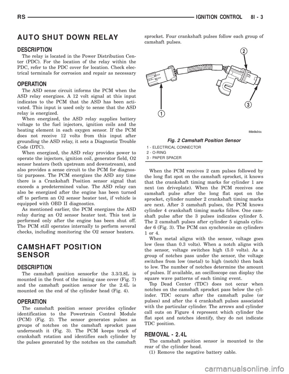
The camshaft position sensor provides cylinder
identification to the Powertrain Control Module
(PCM) (Fig. 2). The sensor generates pulses as
groups of notches on the camshaft sprocket pass
underneath it (Fig. 3). The PCM keeps track of
crankshaft rotation and identifies each cylinder by
the pulses generated by the notches on the camshaftsprocket. Four crankshaft pulses follow each group of
camshaft pulses.
When the PCM receives 2 cam pulses followed by
the long flat spot on the camshaft sprocket, it knows
that the crankshaft timing marks for cylinder 1 are
next (on driveplate). When the PCM receives one
camshaft pulse after the long flat spot on the
sprocket, cylinder number 2 crankshaft timing marks
are next. After 3 camshaft pulses, the PCM knows
cylinder 4 crankshaft timing marks follow. One cam-
shaft pulse after the 3 pulses indicates cylinder 5.
The 2 camshaft pulses after cylinder 5 signals cylin-
der 6 (Fig. 3). The PCM can synchronize on cylinders
1or4.
When metal aligns with the sensor, voltage goes
low (less than 0.3 volts). When a notch aligns with
the sensor, voltage switches high (5.0 volts). As a
group of notches pass under the sensor, the voltage
switches from low (metal) to high (notch) then back
to low. The number of notches determine the amount
of pulses. If available, an oscilloscope can display the
square wave patterns of each timing event.
Top Dead Center (TDC) does not occur when
notches on the camshaft sprocket pass below the cyl-
inder. TDC occurs after the camshaft pulse (or
pulses) and after the 4 crankshaft pulses associated
with the particular cylinder. The arrows and cylinder
call outs on Figure 4 represent which cylinder the
flat spot and notches identify, they do not indicate
TDC position.
REMOVAL - 2.4L
The camshaft position sensor is mounted to the
rear of the cylinder head.
(1) Remove the negative battery cable.
Fig. 2 Camshaft Position Sensor
1 - ELECTRICAL CONNECTOR
2 - O-RING
3 - PAPER SPACER
RSIGNITION CONTROL8I-3
Page 1920 of 4284
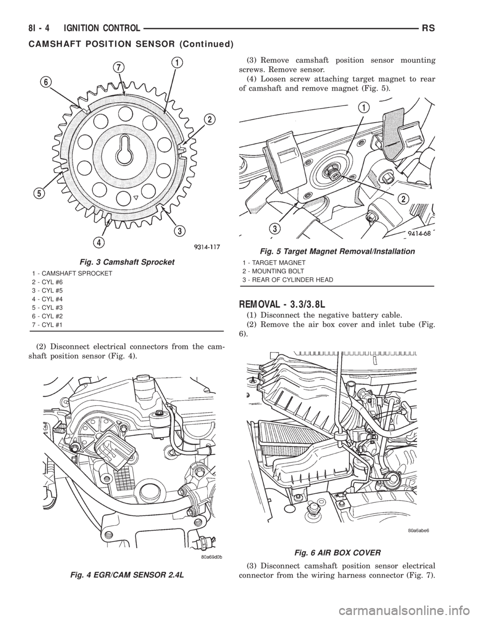
(2) Disconnect electrical connectors from the cam-
shaft position sensor (Fig. 4).(3) Remove camshaft position sensor mounting
screws. Remove sensor.
(4) Loosen screw attaching target magnet to rear
of camshaft and remove magnet (Fig. 5).
REMOVAL - 3.3/3.8L
(1) Disconnect the negative battery cable.
(2) Remove the air box cover and inlet tube (Fig.
6).
(3) Disconnect camshaft position sensor electrical
connector from the wiring harness connector (Fig. 7).
Fig. 3 Camshaft Sprocket
1 - CAMSHAFT SPROCKET
2 - CYL #6
3 - CYL #5
4 - CYL #4
5 - CYL #3
6 - CYL #2
7 - CYL #1
Fig. 4 EGR/CAM SENSOR 2.4L
Fig. 5 Target Magnet Removal/Installation
1 - TARGET MAGNET
2 - MOUNTING BOLT
3 - REAR OF CYLINDER HEAD
Fig. 6 AIR BOX COVER
8I - 4 IGNITION CONTROLRS
CAMSHAFT POSITION SENSOR (Continued)
Page 1921 of 4284
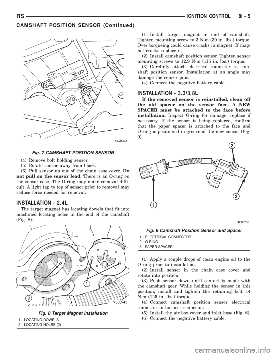
(4) Remove bolt holding sensor.
(5) Rotate sensor away from block.
(6) Pull sensor up out of the chain case cover.Do
not pull on the sensor lead.There is an O-ring on
the sensor case. The O-ring may make removal diffi-
cult. A light tap to top of sensor prior to removal may
reduce force needed for removal.
INSTALLATION - 2.4L
The target magnet has locating dowels that fit into
machined locating holes in the end of the camshaft
(Fig. 8).(1) Install target magnet in end of camshaft.
Tighten mounting screw to 3 N´m (30 in. lbs.) torque.
Over torqueing could cause cracks in magnet. If mag-
net cracks replace it.
(2) Install camshaft position sensor. Tighten sensor
mounting screws to 12.9 N´m (115 in. lbs.) torque.
(3) Carefully attach electrical connector to cam-
shaft position sensor. Installation at an angle may
damage the sensor pins.
(4) Connect the negative battery cable.
INSTALLATION - 3.3/3.8L
If the removed sensor is reinstalled, clean off
the old spacer on the sensor face. A NEW
SPACER must be attached to the face before
installation.Inspect O-ring for damage, replace if
necessary. If the sensor is being replaced, confirm
that the paper spacer is attached to the face and
O-ring is positioned in groove of the new sensor (Fig.
9).
(1) Apply a couple drops of clean engine oil to the
O-ring prior to installation.
(2) Install sensor in the chain case cover and
rotate into position.
(3) Push sensor down until contact is made with
the camshaft gear. While holding the sensor in this
position, install and tighten the retaining bolt 14
N´m (125 in. lbs.) torque.
(4) Connect camshaft position sensor electrical
connector to harness connector.
(5) Install the air box cover and inlet hose (Fig. 6).
(6) Connect the negative battery cable.
Fig. 7 CAMSHAFT POSITION SENSOR
Fig. 8 Target Magnet Installation
1 - LOCATING DOWELS
2 - LOCATING HOLES (2)
Fig. 9 Camshaft Position Sensor and Spacer
1 - ELECTRICAL CONNECTOR
2 - O-RING
3 - PAPER SPACER
RSIGNITION CONTROL8I-5
CAMSHAFT POSITION SENSOR (Continued)
Page 1922 of 4284
IGNITION COIL
DESCRIPTION
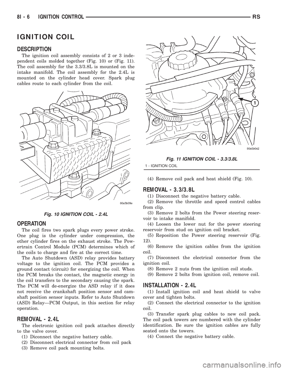
The ignition coil assembly consists of 2 or 3 inde-
pendent coils molded together (Fig. 10) or (Fig. 11).
The coil assembly for the 3.3/3.8L is mounted on the
intake manifold. The coil assembly for the 2.4L is
mounted on the cylinder head cover. Spark plug
cables route to each cylinder from the coil.
OPERATION
The coil fires two spark plugs every power stroke.
One plug is the cylinder under compression, the
other cylinder fires on the exhaust stroke. The Pow-
ertrain Control Module (PCM) determines which of
the coils to charge and fire at the correct time.
The Auto Shutdown (ASD) relay provides battery
voltage to the ignition coil. The PCM provides a
ground contact (circuit) for energizing the coil. When
the PCM breaks the contact, the magnetic energy in
the coil transfers to the secondary causing the spark.
The PCM will de-energize the ASD relay if it does
not receive the crankshaft position sensor and cam-
shaft position sensor inputs. Refer to Auto Shutdown
(ASD) RelayÐPCM Output, in this section for relay
operation.
REMOVAL - 2.4L
The electronic ignition coil pack attaches directly
to the valve cover.
(1) Diconnect the negative battery cable.
(2) Disconnect electrical connector from coil pack
(3) Remove coil pack mounting bolts.(4) Remove coil pack and heat shield (Fig. 10).
REMOVAL - 3.3/3.8L
(1) Disconnect the negative battery cable.
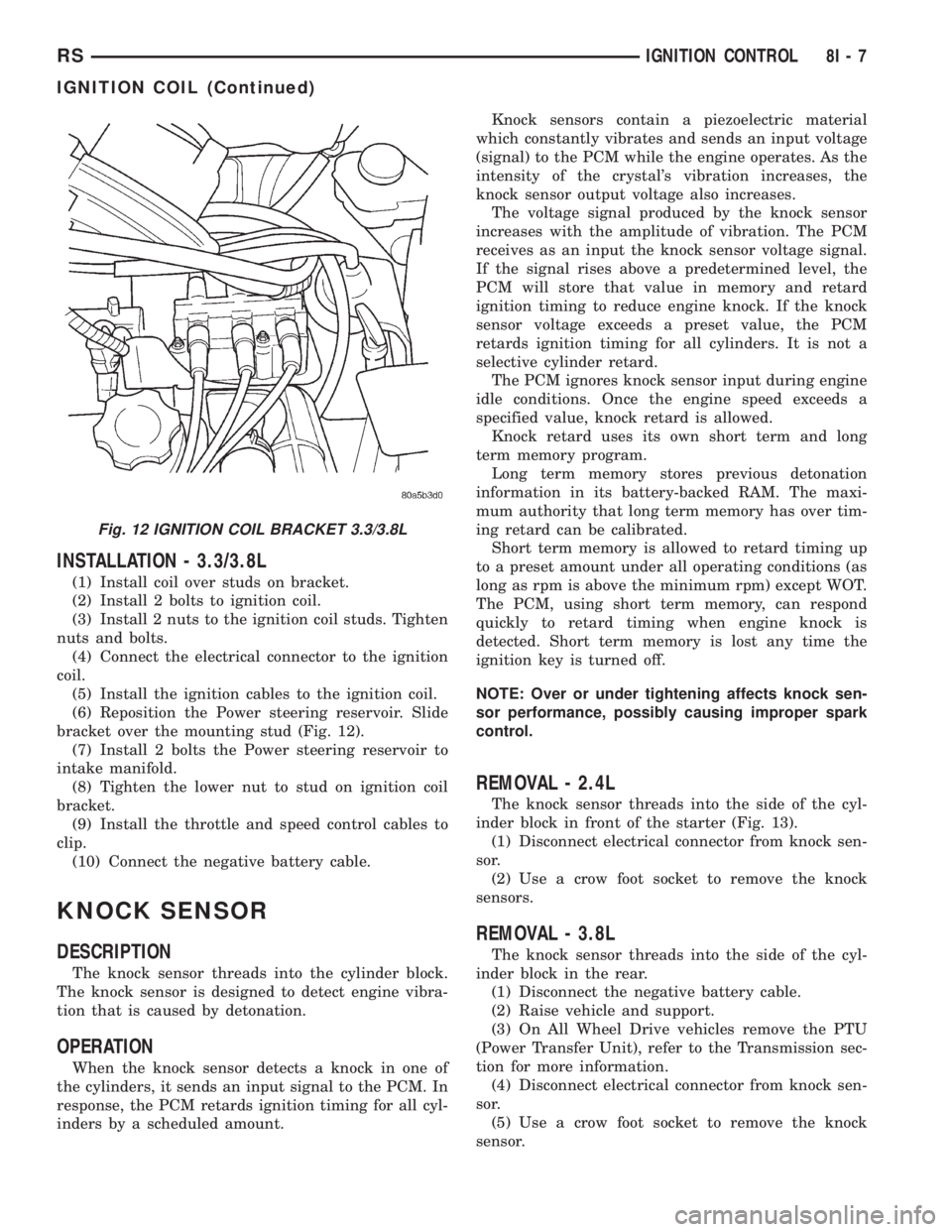
(2) Remove the throttle and speed control cables
from clip.
(3) Remove 2 bolts from the Power steering reser-
voir to intake manifold.
(4) Loosen the lower nut for the power steering
reservoir from stud on ignition coil bracket.
(5) Reposition the Power steering reservoir (Fig.
12).
(6) Remove the ignition cables from the ignition
coil.
(7) Disconnect the electrical connector from the
ignition coil.
(8) Remove 2 nuts from the ignition coil studs.
(9) Remove 2 bolts from ignition coil, remove coil.
INSTALLATION - 2.4L
(1) Install ignition coil and heat shield to valve
cover and tighten bolts.
(2) Connect the electrical connector to the ignition
coil.
(3) Transfer spark plug cables to new coil pack.
The coil pack towers are numbered with the cylinder
identification. Be sure the ignition cables are fully
seated onto the towers.
(4) Connect the negative battery cable.
Fig. 10 IGNITION COIL - 2.4L
Fig. 11 IGNITION COIL - 3.3/3.8L
1 - IGNITION COIL
8I - 6 IGNITION CONTROLRS
Page 1923 of 4284
INSTALLATION - 3.3/3.8L
(1) Install coil over studs on bracket.
(2) Install 2 bolts to ignition coil.
(3) Install 2 nuts to the ignition coil studs. Tighten
nuts and bolts.
(4) Connect the electrical connector to the ignition
coil.
(5) Install the ignition cables to the ignition coil.
(6) Reposition the Power steering reservoir. Slide
bracket over the mounting stud (Fig. 12).
(7) Install 2 bolts the Power steering reservoir to
intake manifold.
(8) Tighten the lower nut to stud on ignition coil
bracket.
(9) Install the throttle and speed control cables to
clip.
(10) Connect the negative battery cable.
KNOCK SENSOR
DESCRIPTION
The knock sensor threads into the cylinder block.
The knock sensor is designed to detect engine vibra-
tion that is caused by detonation.
OPERATION
When the knock sensor detects a knock in one of
the cylinders, it sends an input signal to the PCM. In
response, the PCM retards ignition timing for all cyl-
inders by a scheduled amount.Knock sensors contain a piezoelectric material
which constantly vibrates and sends an input voltage
(signal) to the PCM while the engine operates. As the
intensity of the crystal's vibration increases, the
knock sensor output voltage also increases.
The voltage signal produced by the knock sensor
increases with the amplitude of vibration. The PCM
receives as an input the knock sensor voltage signal.
If the signal rises above a predetermined level, the
PCM will store that value in memory and retard
ignition timing to reduce engine knock. If the knock
sensor voltage exceeds a preset value, the PCM
retards ignition timing for all cylinders. It is not a
selective cylinder retard.
The PCM ignores knock sensor input during engine
idle conditions. Once the engine speed exceeds a
specified value, knock retard is allowed.
Knock retard uses its own short term and long
term memory program.
Long term memory stores previous detonation
information in its battery-backed RAM. The maxi-
mum authority that long term memory has over tim-
ing retard can be calibrated.
Short term memory is allowed to retard timing up
to a preset amount under all operating conditions (as
long as rpm is above the minimum rpm) except WOT.
The PCM, using short term memory, can respond
quickly to retard timing when engine knock is
detected. Short term memory is lost any time the
ignition key is turned off.
NOTE: Over or under tightening affects knock sen-
sor performance, possibly causing improper spark
control.
REMOVAL - 2.4L
The knock sensor threads into the side of the cyl-
inder block in front of the starter (Fig. 13).
(1) Disconnect electrical connector from knock sen-
sor.
(2) Use a crow foot socket to remove the knock
sensors.
REMOVAL - 3.8L
The knock sensor threads into the side of the cyl-
inder block in the rear.
(1) Disconnect the negative battery cable.
(2) Raise vehicle and support.
(3) On All Wheel Drive vehicles remove the PTU
(Power Transfer Unit), refer to the Transmission sec-
tion for more information.
(4) Disconnect electrical connector from knock sen-
sor.
(5) Use a crow foot socket to remove the knock
sensor.
Fig. 12 IGNITION COIL BRACKET 3.3/3.8L
RSIGNITION CONTROL8I-7
IGNITION COIL (Continued)