2001 CHRYSLER VOYAGER sensor
[x] Cancel search: sensorPage 1971 of 4284
driving out of a heated garage into winter tempera-
tures.
When the ignition switch is turned to the Off posi-
tion, the last displayed temperature reading stays in
the electronic control modules (CT, CMTC, EVIC)
memory. When the ignition switch is turned to the
On position again, the electronic module will display
the memory temperature for one minute; then update
the display to the current average temperature read-
ing within five minutes.
The thermometer function is supported by an
ambient temperature sensor. The sensor is mounted
outside the passenger compartment near the front
and center of the vehicle, and is hard wired to the
Front Control Module (FCM). The FCM sends tem-
perature status messages to the module over the
J1850 PCI data bus circuit.
Following are general descriptions of the major
components used in the overhead console. Refer to
Wiring Diagrams for complete circuit schematics.
OPERATION
Refer to the vehicle Owner's Manual for specific
operation of each overhead console and its systems.
DIAGNOSIS & TESTING - OVERHEAD
CONSOLE
If the problem with the overhead console is an
inaccurate or scrambled display, refer toSelf-Diag-
nostic Testlater in this group. If the problem with
the overhead console is incorrect Vacuum Fluorescent
Display (VFD) dimming levels, use a DRB IIItscan
tool and the proper Diagnostic Procedures manual to
test for the correct dimming message inputs being
received from the Body Control Module (BCM) or
Front Control Module (FCM) over the J1850 Pro-
grammable Communications Interface (PCI) data bus
circuit. If the problem is a no-display condition, use
the following procedures. For complete circuit dia-
grams, refer toOverhead Consolein the Wiring
Diagrams section of the service manual.
(1) Check the fused B(+) fuse in the intelligent
power module. If OK, go to Step 2. If not OK, repair
the shorted circuit or component as required and
replace the faulty fuse.
(2) Check for battery voltage at the fused B(+) fuse
in the intelligent power module. If OK, go to Step 3.
If not OK, repair the open fused B(+) circuit to the
fused B(+) fuse in the intelligent power module as
required.
(3) Check the fused ignition switch output (run/
start) fuse in the intelligent power module. If OK, go
to Step 4. If not OK, repair the shorted circuit or
component as required and replace the faulty fuse.
(4) Turn the ignition switch to the On position.
Check for battery voltage at the fused ignition switchoutput (run/start) fuse in the intelligent power mod-
ule. If OK, go to Step 5. If not OK, repair the open
fused ignition switch output (run/start) circuit to the
ignition switch as required.
(5) Turn the ignition switch to the Off position.
Disconnect and isolate the battery negative cable.
Remove the overhead console. Check for continuity
between the ground circuit cavity of the roof wire
harness connector for the electronics module and a
good ground. There should be continuity. If OK, go to
Step 6. If not OK, repair the open ground circuit to
ground as required.
(6) Connect the battery negative cable. Check for
battery voltage at the fused B(+) circuit cavity of the
roof wire harness connector for the electronics mod-
ule. If OK, go to Step 7. If not OK, repair the open
fused B(+) circuit to the fused B(+) fuse in the intel-
ligent power module as required.
(7) Turn the ignition switch to the On position.
Check for battery voltage at the fused ignition switch
output (run/start) circuit cavity of the roof wire har-
ness connector for the electronics module. If OK,
refer toSelf-Diagnostic Testlater this group for
further diagnosis of the electronics module and the
J1850 PCI data bus circuit. If not OK, repair the
open fused ignition switch output (run/start) circuit
to the fuse in the intelligent power module as
required.
SELF-DIAGNOSTIC TEST
A self-diagnostic test is used to determine that the
electronics module is operating properly, and that all
the J1850 PCI data bus messages are being received
for initial operation. Initiate the self-diagnostic test
as follows:
(1) With the ignition switch in the Off position, on
Electronic Vehicle Information Center (EVIC) and
Compass Mini-Trip Computer (CMTC) equipped vehi-
cles simultaneously depress and hold theSTEP and
the RESET buttons. On Compass Temperature
Module (CT) equipped vehicles depress theC/T and
the US/M push buttons.
(2) Turn the ignition switch to the On position.
(3) Following completion of these tests, the elec-
tronics module will display one of the following mes-
sages:
²Pass Self Test (EVIC only), PASS (CT,
CMTC)- The electronics module is working properly.
²Failed Self Test (EVIC only), FAIL (CT,
CMTC)- The electronics module has an internal fail-
ure. The electronics module is faulty and must be
replaced.
²Failed J1850 Communication (EVIC only),
BUS (CT, CMTC)- The electronics module is not
receiving proper message input through the J1850
PCI data bus circuit. This can result from one or
RSOVERHEAD CONSOLE8M-3
OVERHEAD CONSOLE (Continued)
Page 1975 of 4284
The EVIC module contains a central processing
unit and interfaces with other electronic modules in
the vehicle over the Programmable Communications
Interface (PCI) J1850 data bus circuit. The PCI data
bus circuit allows the sharing of sensor information.
This helps to reduce wire harness complexity, reduce
internal controller hardware, and reduce component
sensor current loads. At the same time, this system
provides increased reliability, enhanced diagnostics,
and allows the addition of many new feature capabil-
ities.
The EVIC ªMenuº push button provides the vehicle
operator with a user interface, which allows the
selection of several optional customer programmable
electronic features to suit individual preferences.
Refer toELECTRONIC VEHICLE INFORMA-
TION CENTER PROGRAMMINGin the Service
Procedures section of this group for more information
on the customer programmable feature options.
If the vehicle is equipped with the optional
Homelinkttransceiver, the EVIC will also display
messages and an icon indicating when the
Homelinkttransceiver is being trained, which of the
three transmitter buttons is transmitting, and when
the transceiver is cleared.
Data input for all EVIC functions, including VFD
dimming level, is received through the J1850 PCI
data bus circuit. The EVIC module uses its internal
programming and all of its data inputs to calculate
and display the requested data. If the data displayed
is incorrect, perform the self-diagnostic tests as
described in this group. If these tests prove inconclu-
sive, the use of a DRBIIItscan tool and the proper
Diagnostic Procedures manual are recommended for
further testing of the EVIC module and the J1850
PCI data bus circuit.
The EVIC module cannot be repaired, and is avail-
able for service only as a unit. This unit includes the
plastic module and display lens. If any of these com-
ponents is faulty or damaged, the complete EVIC
module must be replaced.
OPERATION
The EVIC has access to both non-switched and
ignition switched sources of battery current so that
some of its features remain operational at any time,
while others may only operate with the ignition
switch in the On position. When the ignition switch
is turned to the On position, the EVIC module VFD
will return to the last function being displayed before
the ignition was turned to the Off position.
The compass/thermometer display is the normal
EVIC display. With the ignition switch in the Onposition, momentarily depressing and releasing the
C/T (compass/thermometer) push button switch will
cause the EVIC to return to the compass/thermome-
ter/trip computer display mode from any other mode.
While in the compass/thermometer/trip computer dis-
play mode, momentarily depressing and releasing the
Step push button will step through the available trip
computer display options.
The EVIC trip computer features several functions
that can be reset. The functions that can be reset
are: average fuel economy, trip odometer and elapsed
time. With the ignition switch in the On position and
with one of the functions of the trip computer that
can be reset currently displayed, depressing the
Reset push button twice within three seconds will
perform a global reset, and all of the trip computer
information that can be reset will be reset to zero.
With the ignition switch in the On position and the
function that is to be reset currently displayed,
momentarily depressing and releasing the Reset
push button once will perform a local reset, and only
the value of the displayed function will be reset to
zero. A global or local reset will only occur if the
function currently displayed is a function that can be
reset. The distance to service function can also be
reset using the local reset method, but it will reset
back to the Service Interval distance that is set in
the EVIC programmable features mode. Refer to
ELECTRONIC VEHICLE INFORMATION CEN-
TER PROGRAMMINGin the Service Procedures
section of this group for more information on setting
the Service Interval.
For more information on the features, control func-
tions and setting procedures for the EVIC module,
see the owner's manual in the vehicle glove box.
DIAGNOSIS & TESTING - ELECTRONIC
VEHICLE INFORMATION CENTER
Electronic Vehicle Information Center (EVIC) data
is obtained from the Body Control Module (BCM) on
the J1850 Data Bus circuit. The EVIC will display
dashes (- -) for any of the screens it did not receive
the bus messages. The label corresponding to the
missing information will be lit. If no EVIC data is
displayed, check the J1850 Data Bus circuit commu-
nications and the BCM. If the brightness level is
improper check the J1850 Data Bus circuit.
The DRB IIItis recommended for checking the
J1850 Data Bus circuit and the BCM. Perform the
EVIC self diagnosis before replacing the EVIC mod-
ule.
RSOVERHEAD CONSOLE8M-7
ELECTRONIC VEHICLE INFO CENTER (Continued)
Page 1979 of 4284
DIAGNOSIS & TESTING - HOMELINKT
If the Homelinktis inoperative, but the Electronic
Vehicle Information Center (EVIC) or Compass Mini-
Trip Computer is operating normally, see the owner's
manual in the vehicle glove box for instructions on
training the Homelinkt. Retrain the Homelinktwith
a known good transmitter as instructed in the own-
er's manual and test the Homelinktoperation again.
If the unit is still inoperative, replace the faulty
Homelinktand EVIC/CMTC module as a unit. If
both the Homelinktand the EVIC/CMTC module are
inoperative, refer toOverhead Console Diagnosis
and Testingearlier in this group for further diagno-
sis. For complete circuit diagrams, refer toOver-
head Consolein Wiring Diagrams.
AMBIENT TEMP SENSOR
DESCRIPTION
Ambient air temperature is monitored by the over-
head console through ambient temperature messages
received from the Front Control Module (FCM) over
the Programmable Communications Interface (PCI)
J1850 data bus circuit. The FCM receives a hard
wired input from the ambient temperature sensor.
The ambient temperature sensor is a variable resis-
tor mounted to a bracket that is secured with a screw
to the right side of the headlamp mounting module
grille opening, behind the radiator grille and in front
of the engine compartment.
Refer toFront Control Modulein Electronic
Control Modules. For complete circuit diagrams, refer
to the appropriate wiring information. The ambient
temperature sensor cannot be adjusted or repaired
and, if faulty or damaged, it must be replaced.
OPERATION
The ambient temperature sensor is a variable
resistor that operates on a five-volt reference signal
sent to it by the Front Control Module. The resis-
tance in the sensor changes as temperature changes,
changing the temperature sensor signal circuit volt-
age to the Front Control Module. Based upon the
resistance in the sensor, the Front Control Module
senses a specific voltage on the temperature sensor
signal circuit, which it is programmed to correspond
to a specific temperature. The Front Control Module
then sends the proper ambient temperature mes-
sages to the EVIC, CMTC over the PCI J1850 data
bus.
The thermometer function is supported by the
ambient temperature sensor, a wiring circuit, the
Front Control Module, the Programmable Communi-
cations Interface (PCI) data bus, and a portion of the
Electronics module. If any portion of the ambienttemperature sensor circuit fails, the Front Control
Module will self-diagnose the circuit.
The ambient temperature sensor circuit can also be
diagnosed by referring toDiagnosis and Testing -
Ambient Temperature Sensor, and Diagnosis
and Testing - Ambient Temperature Sensor Cir-
cuit. If the temperature sensor and circuit are con-
firmed to be OK, but the temperature display is
inoperative or incorrect, refer toDiagnosis and
Testing - Overhead Consolein this group. For
complete circuit diagrams, refer to the appropriate
wiring information.
DIAGNOSIS AND TESTING - AMBIENT
TEMPERATURE SENSOR
(1) Turn the ignition switch to the Off position.
Disconnect and isolate the battery negative cable.
Disconnect the ambient temperature sensor wire har-
ness connector.
(2) Measure the resistance of the ambient temper-
ature sensor. At ±40É C (±40É F), the sensor resis-
tance is 336 kilohms. At 55É C (140É F), the sensor
resistance is 2.488 kilohms. The sensor resistance
should read between these two values. If OK, refer to
Diagnosis and Testing - Ambient Temperature
Sensor Circuitin this group. If not OK, replace the
faulty ambient temperature sensor.
DIAGNOSIS AND TESTING - AMBIENT
TEMPERATURE SENSOR CIRCUIT
(1) Turn the ignition switch to the Off position.
Disconnect and isolate the battery negative cable.
Disconnect the ambient temperature sensor wire har-
ness connector and the Front Control Module wire
harness connector.
(2) Connect a jumper wire between the two termi-
nals in the body half of the ambient temperature sen-
sor wire harness connector.
(3) Check for continuity between the sensor return
circuit and the ambient temperature sensor signal
circuit cavities of the Front Control Module wire har-
ness connector. There should be continuity. If OK, go
to Step 4. If not OK, repair the open sensor return
circuit or ambient temperature sensor signal circuit
to the ambient temperature sensor as required.
(4) Remove the jumper wire from the body half of
the ambient temperature sensor wire harness con-
nector. Check for continuity between the sensor
return circuit cavity of the Front Control Module
wire harness connector and a good ground. There
should be no continuity. If OK, go to Step 5. If not
OK, repair the shorted sensor return circuit as
required.
(5) Check for continuity between the ambient tem-
perature sensor signal circuit cavity of the Front
Control Module wire harness connector and a good
RSOVERHEAD CONSOLE8M-11
UNIVERSAL TRANSMITTER (Continued)
Page 1980 of 4284

ground. There should be no continuity. If OK, refer to
Diagnosis and Testing - Overhead Consolein
this group. If not OK, repair the shorted ambient
temperature sensor signal circuit as required.
REMOVAL
(1) Disconnect and isolate the battery negative
cable.
(2) Raise and support vehicle on safety stands.(3) From behind front bumper fascia, remove
screw holding sensor to radiator closure panel.
(4) Remove sensor from vehicle.
INSTALLATION
(1) Position the sensor in the vehicle.
(2) From behind the front bumper fascia, install
the screw holding sensor to radiator closure panel.
(3) Connect the battery negative cable.
8M - 12 OVERHEAD CONSOLERS
AMBIENT TEMP SENSOR (Continued)
Page 1981 of 4284

POWER SYSTEMS
TABLE OF CONTENTS
page page
POWER LIFTGATE SYSTEM.................. 1
POWER SLIDING DOOR SYSTEM............ 19
POWER LOCKS........................... 39POWER MIRRORS........................ 45
POWER SEATS........................... 49
POWER WINDOWS........................ 60
POWER LIFTGATE SYSTEM
TABLE OF CONTENTS
page page
POWER LIFTGATE SYSTEM
DESCRIPTION............................2
OPERATION.............................3
DIAGNOSIS AND TESTING..................4
DIAGNOSIS AND TESTING - POWER
LIFTGATE SYSTEM......................4
STANDARD PROCEDURE...................9
LIFTGATE ADJUSTMENT..................9
POWER LIFTGATE LEARN CYCLE..........9
PINCH SENSOR
DESCRIPTION............................9
OPERATION.............................9
REMOVAL...............................9
INSTALLATION...........................10
FULL OPEN SWITCH
DESCRIPTION...........................10
OPERATION.............................10
REMOVAL..............................10
INSTALLATION...........................10
LIFTGATE MOTOR
DESCRIPTION...........................11
OPERATION.............................11
REMOVAL..............................11
INSTALLATION...........................11
ENGAGE ACTUATOR
DESCRIPTION...........................12
OPERATION.............................12
REMOVAL..............................12
INSTALLATION...........................12TRANSVERSE BRACKET
DESCRIPTION...........................13
OPERATION.............................13
REMOVAL..............................13
INSTALLATION...........................13
LIFT GEAR & LINK ROD
DESCRIPTION...........................14
OPERATION.............................14
REMOVAL..............................14
INSTALLATION...........................14
LATCH
DESCRIPTION...........................15
OPERATION.............................15
REMOVAL..............................15
INSTALLATION...........................15
LATCH ACTUATOR
DESCRIPTION...........................16
OPERATION.............................16
REMOVAL..............................16
INSTALLATION...........................16
EXTERIOR HANDLE SWITCH
DESCRIPTION...........................17
OPERATION.............................17
REMOVAL..............................17
INSTALLATION...........................17
CHIME/THERMISTOR
DESCRIPTION...........................18
OPERATION.............................18
REMOVAL..............................18
INSTALLATION...........................18
RSPOWER SYSTEMS8N-1
Page 1982 of 4284
POWER LIFTGATE SYSTEM
DESCRIPTION
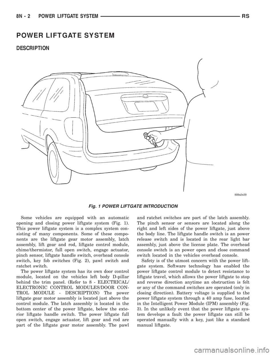
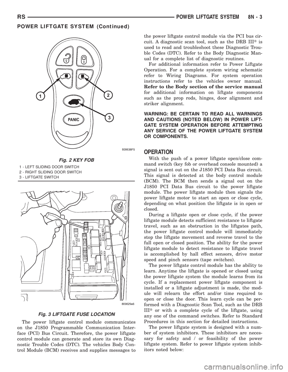
Some vehicles are equipped with an automatic
opening and closing power liftgate system (Fig. 1).
This power liftgate system is a complex system con-
sisting of many components. Some of these compo-
nents are the liftgate gear motor assembly, latch
assembly, lift gear and rod, liftgate control module,
chime/thermistor, full open switch, engage actuator,
pinch sensor, liftgate handle switch, overhead console
switch, key fob switches (Fig. 2), pawl switch and
ratchet switch.
The power liftgate system has its own door control
module, located on the vehicles left body D-pillar
behind the trim panel. (Refer to 8 - ELECTRICAL/
ELECTRONIC CONTROL MODULES/DOOR CON-
TROL MODULE - DESCRIPTION) The power
liftgate gear motor assembly is located just above the
control module. The latch assembly is located in the
bottom center of the power liftgate, below the exte-
rior liftgate handle switch. The power liftgate full
open switch, engage actuator, lift gear and rod are
part of the liftgate gear motor assembly. The pawland ratchet switches are part of the latch assembly.
The pinch sensor or sensors are located along the
right and left sides of the power liftgate, just above
the body line. The liftgate handle switch is an power
release switch and is located in the rear light bar
assembly, just above the license plate. The overhead
console switch is an power open and close command
switch located in the vehicles overhead console.
Safety is of the utmost concern with the power lift-
gate system. Software technology has enabled the
power liftgate control module to detect resistance to
liftgate travel, which allows the power liftgate to stop
and reverse direction anytime an obstruction is felt
or any of the command switches are operated (only in
closing direction). Battery voltage is supplied to the
power liftgate system through a 40 amp fuse, located
in the Intelligent Power Module (IPM) assembly (Fig.
3). In the unlikely event that the power liftgate sys-
tem develops a fault the power liftgate can still be
operated manually with a key, just like a standard
manual liftgate.
Fig. 1 POWER LIFTGATE INTRODUCTION
8N - 2 POWER LIFTGATE SYSTEMRS
Page 1983 of 4284
The power liftgate control module communicates
on the J1850 Programmable Communication Inter-
face (PCI) Bus Circuit. Therefore, the power liftgate
control module can generate and store its own Diag-
nostic Trouble Codes (DTC). The vehicles Body Con-
trol Module (BCM) receives and supplies messages tothe power liftgate control module via the PCI bus cir-
cuit. A diagnostic scan tool, such as the DRB IIItis
used to read and troubleshoot these Diagnostic Trou-
ble Codes (DTC). Refer to the Body Diagnostic Man-
ual for a complete list of diagnostic routines.
For additional information refer to Power Liftgate
Operation. For a complete system wiring schematic
refer to Wiring Diagrams. For system operation
instructions refer to the vehicles owner manual.
Refer to the Body section of the service manual
for additional information on liftgate components
such as the prop rods, hinges, door alignment and
striker alignment.
WARNING: BE CERTAIN TO READ ALL WARNINGS
AND CAUTIONS (NOTED BELOW) IN POWER LIFT-
GATE SYSTEM OPERATION BEFORE ATTEMPTING
ANY SERVICE OF THE POWER LIFTGATE SYSTEM
OR COMPONENTS.
OPERATION
With the push of a power liftgate open/close com-
mand switch (key fob or overhead console mounted) a
signal is sent out on the J1850 PCI Data Bus circuit.
This signal is detected at the body control module
(BCM). The BCM then sends a signal out on the
J1850 PCI Data Bus circuit to the power liftgate
module. The power liftgate module then signals the
power liftgate motor to start an open or close cycle,
depending on what position the liftgate is in open or
closed.
During a liftgate open or close cycle, if the power
liftgate module detects sufficient resistance to liftgate
travel, such as an obstruction in the liftgates path,
the power liftgate control module will immediately
stop the liftgate movement and reverse travel to the
full open or closed position. The ability for the power
liftgate module to detect resistance to liftgate travel
is accomplished by hall effect sensors, drive motor
speed and pinch sensors (tape switches).
The power liftgate control module has the ability to
learn. Anytime the liftgate is opened or closed using
the power liftgate system the module learns from its
cycle. If a replacement power liftgate component is
installed or a liftgate adjustment is made, the mod-
ule will relearn the effort and/or time required to
open or close the door. This learn cycle can be per-
formed with a Diagnostic Scan Tool, such as the DRB
IIItor with a complete cycle of the liftgate, using
any one of the command switches. Refer to Standard
Procedures in this section for detailed instructions.
The power liftgate system is designed with a num-
ber of system inhibitors. These inhibitors are neces-
sary for safety and / or feasibility of the power
liftgate system. Refer to power liftgate system inhib-
itors noted below:Fig. 2 KEY FOB
1 - LEFT SLIDING DOOR SWITCH
2 - RIGHT SLIDING DOOR SWITCH
3 - LIFTGATE SWITCH
Fig. 3 LIFTGATE FUSE LOCATION
RSPOWER LIFTGATE SYSTEM8N-3
POWER LIFTGATE SYSTEM (Continued)
Page 1984 of 4284
POWER LIFTGATE SYSTEM INHIBITORS
²The Power Liftgate may not operate in extreme
temperatures. These extreme temperatures will be
approximately -12É F (-24.4É C) on the low side and
143É F (61.6É C) for the high side. A chime/thermister
assembly in the rear light bar assembly monitors the
outside temperature.
²The vehicles transmission must be in park or
neutral for the power liftgate to start a cycle.
²If multiple obstacles are detected during the
same power open or close cycle the liftgate goes into
manual operation.
²If severe Diagnostic Trouble Codes (DTC) are
stored in the power liftgate control module.
POWER LIFTGATE SYSTEM CAUTIONS AND
WARNINGS
WARNING: ALWAYS DISCONNECT THE NEGATIVE
BATTERY CABLE BEFORE ATTEMPTING ANY
POWER LIFTGATE SYSTEM SERVICE.
WARNING: THERE IS A SMALL AREA ON BOTH
SIDES OF THE LOWER POWER LIFTGATE WHICH
ARE NOT PROTECTED BY PINCH SENSORS.
EXTREME CARE MUST BE TAKEN TO PREVENT
OBJECTS FROM ENTERING THIS AREA ONCE THE
LIFTGATE REACHES THE SECONDARY LATCH
CONTACT (APPROXIMATELY 1/2 INCH BEFORE
FULLY CLOSED).
WARNING: NEVER ATTEMPT TO ENTER OR EXIT
THE VEHICLE WITH THE LIFTGATE IN MOTION.
YOU COULD DAMAGE THE POWER LIFTGATE SYS-
TEM AND/OR COMPONENTS AND/OR CAUSE PER-
SONAL INJURY.
WARNING: NEVER STICK OBJECTS IN THE POWER
LIFTGATE WHEN CINCHING CLOSED. YOU COULDDAMAGE THE VEHICLE, POWER LIFTGATE SYS-
TEM COMPONENTS AND/OR CAUSE PERSONAL
INJURY.
DIAGNOSIS AND TESTING - POWER LIFTGATE
SYSTEM
The power opening and closing power liftgate sys-
tem is a complex system containing many compo-
nents and modules. In order to obtain conclusive
testing the Programmable Communications Interface
(J1850) data bus network and all of the electronic
modules that provide inputs to, or receive outputs
from the power liftgate system must be checked.
The power liftgate system was designed to be diag-
nosed with an appropriate diagnostic scan tool, such
as the DRB IIIt. The most reliable, efficient, and
accurate means to diagnose the power liftgate system
requires the use of a DRB IIItscan tool and the
proper Body Diagnostic Procedures manual. The
DRB IIItcan be used to observe various switch sta-
tuses throughout the power liftgate system to help
the technician diagnose a defective switch or compo-
nent. The DRB IIItcan also be used to actuate var-
ious components throughout the power liftgate
system to help the technician diagnose a defective
component.
Before any testing of the power liftgate system is
attempted, the battery should be fully charged, all
built-in power liftgate system inhibitors read and
understood (Refer to power liftgate system operation)
and all wire harness and ground connections
inspected around the affected areas on the vehicle.
Following are quick reference diagnostic tables to
help when diagnosing and testing the power liftgate
system.
8N - 4 POWER LIFTGATE SYSTEMRS
POWER LIFTGATE SYSTEM (Continued)