2001 CHRYSLER VOYAGER clock
[x] Cancel search: clockPage 149 of 4284
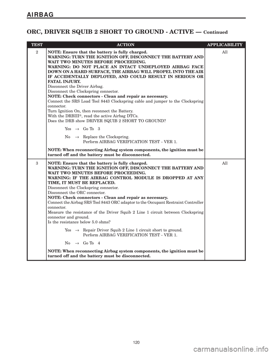
TEST ACTION APPLICABILITY
2NOTE: Ensure that the battery is fully charged.
WARNING: TURN THE IGNITION OFF, DISCONNECT THE BATTERY AND
WAIT TWO MINUTES BEFORE PROCEEDING.
WARNING: DO NOT PLACE AN INTACT UNDEPLOYED AIRBAG FACE
DOWN ON A HARD SURFACE, THE AIRBAG WILL PROPEL INTO THE AIR
IF ACCIDENTALLY DEPLOYED, AND COULD RESULT IN SERIOUS OR
FATAL INJURY.
Disconnect the Driver Airbag.
Disconnect the Clockspring connector.
NOTE: Check connectors - Clean and repair as necessary.
Connect the SRS Load Tool 8443 Clockspring cable and jumper to the Clockspring
connector.
Turn Ignition On, then reconnect the Battery.
With the DRBIIIt, read the active Airbag DTCs.
Does the DRB show DRIVER SQUIB 2 SHORT TO GROUND?All
Ye s®Go To 3
No®Replace the Clockspring.
Perform AIRBAG VERIFICATION TEST - VER 1.
NOTE: When reconnecting Airbag system components, the ignition must be
turned off and the battery must be disconnected.
3NOTE: Ensure that the battery is fully charged.
WARNING: TURN THE IGNITION OFF, DISCONNECT THE BATTERY AND
WAIT TWO MINUTES BEFORE PROCEEDING.
WARNING: IF THE AIRBAG CONTROL MODULE IS DROPPED AT ANY
TIME, IT MUST BE REPLACED.
Disconnect the Clockspring connector.
Disconnect the ORC connector.
NOTE: Check connectors - Clean and repair as necessary.
Connect the Airbag SRS Tool 8443 ORC adaptor to the Occupant Restraint Controller
connector.
Measure the resistance of the Driver Squib 2 Line 1 circuit between Clockspring
connector and ground.
Is the resistance below 5.0 ohms?All
Ye s®Repair Driver Squib 2 Line 1 circuit short to ground.
Perform AIRBAG VERIFICATION TEST - VER 1.
No®Go To 4
NOTE: When reconnecting Airbag system components, the ignition must be
turned off and the battery must be disconnected.
120
AIRBAG
ORC, DRIVER SQUIB 2 SHORT TO GROUND - ACTIVE ÐContinued
Page 150 of 4284
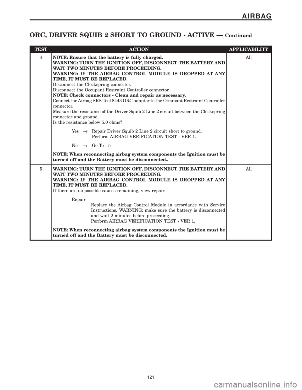
TEST ACTION APPLICABILITY
4NOTE: Ensure that the battery is fully charged.
WARNING: TURN THE IGNITION OFF, DISCONNECT THE BATTERY AND
WAIT TWO MINUTES BEFORE PROCEEDING.
WARNING: IF THE AIRBAG CONTROL MODULE IS DROPPED AT ANY
TIME, IT MUST BE REPLACED.
Disconnect the Clockspring connector.
Disconnect the Occupant Restraint Controller connector.
NOTE: Check connectors - Clean and repair as necessary.
Connect the Airbag SRS Tool 8443 ORC adaptor to the Occupant Restraint Controller
connector.
Measure the resistance of the Driver Squib 2 Line 2 circuit between the Clockspring
connector and ground.
Is the resistance below 5.0 ohms?All
Ye s®Repair Driver Squib 2 Line 2 circuit short to ground.
Perform AIRBAG VERIFICATION TEST - VER 1.
No®Go To 5
NOTE: When reconnecting airbag system components the Ignition must be
turned off and the Battery must be disconnected..
5WARNING: TURN THE IGNITION OFF, DISCONNECT THE BATTERY AND
WAIT TWO MINUTES BEFORE PROCEEDING.
WARNING: IF THE AIRBAG CONTROL MODULE IS DROPPED AT ANY
TIME, IT MUST BE REPLACED.
If there are no possible causes remaining, view repair.All
Repair
Replace the Airbag Control Module in accordance with Service
Instructions. WARNING: make sure the battery is disconnected
and wait 2 minutes before proceeding.
Perform AIRBAG VERIFICATION TEST - VER 1.
NOTE: When reconnecting airbag system components the Ignition must be
turned off and the Battery must be disconnected.
121
AIRBAG
ORC, DRIVER SQUIB 2 SHORT TO GROUND - ACTIVE ÐContinued
Page 246 of 4284
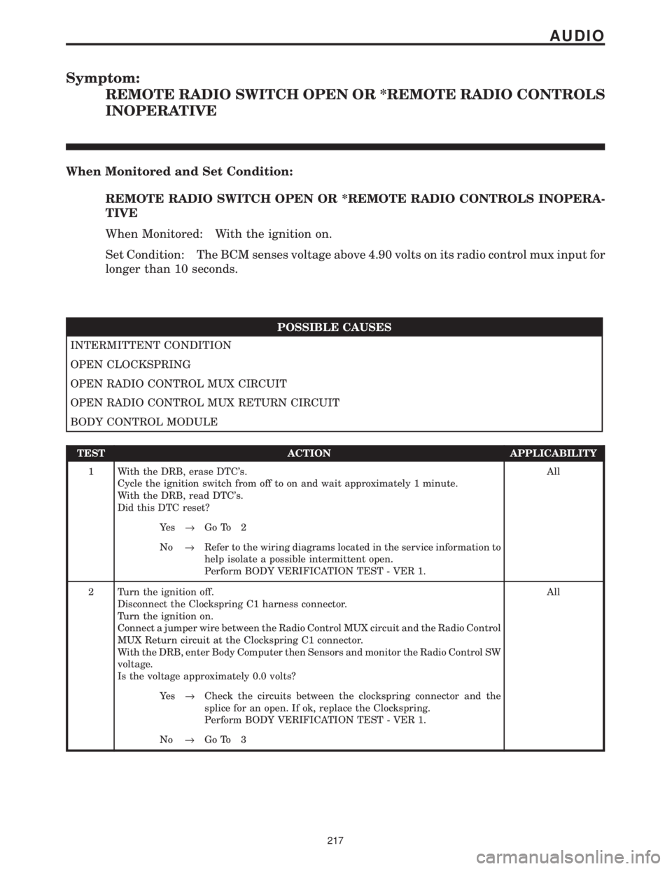
Symptom:
REMOTE RADIO SWITCH OPEN OR *REMOTE RADIO CONTROLS
INOPERATIVE
When Monitored and Set Condition:
REMOTE RADIO SWITCH OPEN OR *REMOTE RADIO CONTROLS INOPERA-
TIVE
When Monitored: With the ignition on.
Set Condition: The BCM senses voltage above 4.90 volts on its radio control mux input for
longer than 10 seconds.
POSSIBLE CAUSES
INTERMITTENT CONDITION
OPEN CLOCKSPRING
OPEN RADIO CONTROL MUX CIRCUIT
OPEN RADIO CONTROL MUX RETURN CIRCUIT
BODY CONTROL MODULE
TEST ACTION APPLICABILITY
1 With the DRB, erase DTC's.
Cycle the ignition switch from off to on and wait approximately 1 minute.
With the DRB, read DTC's.
Did this DTC reset?All
Ye s®Go To 2
No®Refer to the wiring diagrams located in the service information to
help isolate a possible intermittent open.
Perform BODY VERIFICATION TEST - VER 1.
2 Turn the ignition off.
Disconnect the Clockspring C1 harness connector.
Turn the ignition on.
Connect a jumper wire between the Radio Control MUX circuit and the Radio Control
MUX Return circuit at the Clockspring C1 connector.
With the DRB, enter Body Computer then Sensors and monitor the Radio Control SW
voltage.
Is the voltage approximately 0.0 volts?All
Ye s®Check the circuits between the clockspring connector and the
splice for an open. If ok, replace the Clockspring.
Perform BODY VERIFICATION TEST - VER 1.
No®Go To 3
217
AUDIO
Page 247 of 4284
TEST ACTION APPLICABILITY
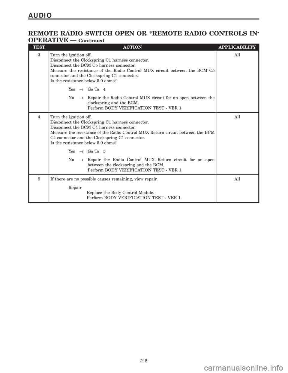
3 Turn the ignition off.
Disconnect the Clockspring C1 harness connector.
Disconnect the BCM C5 harness connector.
Measure the resistance of the Radio Control MUX circuit between the BCM C5
connector and the Clockspring C1 connector.
Is the resistance below 5.0 ohms?All
Ye s®Go To 4
No®Repair the Radio Control MUX circuit for an open between the
clockspring and the BCM.
Perform BODY VERIFICATION TEST - VER 1.
4 Turn the ignition off.
Disconnect the Clockspring C1 harness connector.
Disconnect the BCM C4 harness connector.
Measure the resistance of the Radio Control MUX Return circuit between the BCM
C4 connector and the Clockspring C1 connector.
Is the resistance below 5.0 ohms?All
Ye s®Go To 5
No®Repair the Radio Control MUX Return circuit for an open
between the clockspring and the BCM.
Perform BODY VERIFICATION TEST - VER 1.
5 If there are no possible causes remaining, view repair. All
Repair
Replace the Body Control Module.
Perform BODY VERIFICATION TEST - VER 1.
218
AUDIO
REMOTE RADIO SWITCH OPEN OR *REMOTE RADIO CONTROLS IN-
OPERATIVE Ð
Continued
Page 248 of 4284
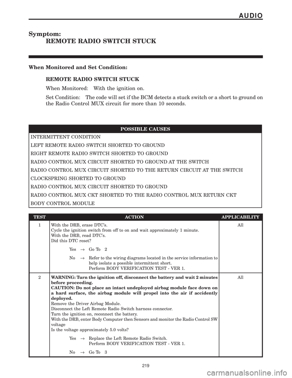
Symptom:
REMOTE RADIO SWITCH STUCK
When Monitored and Set Condition:
REMOTE RADIO SWITCH STUCK
When Monitored: With the ignition on.
Set Condition: The code will set if the BCM detects a stuck switch or a short to ground on
the Radio Control MUX circuit for more than 10 seconds.
POSSIBLE CAUSES
INTERMITTENT CONDITION
LEFT REMOTE RADIO SWITCH SHORTED TO GROUND
RIGHT REMOTE RADIO SWITCH SHORTED TO GROUND
RADIO CONTROL MUX CIRCUIT SHORTED TO GROUND AT THE SWITCH
RADIO CONTROL MUX CIRCUIT SHORTED TO THE RETURN CIRCUIT AT THE SWITCH
CLOCKSPRING SHORTED TO GROUND
RADIO CONTROL MUX CIRCUIT SHORTED TO GROUND
RADIO CONTROL MUX CKT SHORTED TO THE RADIO CONTROL MUX RETURN CKT
BODY CONTROL MODULE
TEST ACTION APPLICABILITY
1 With the DRB, erase DTC's.
Cycle the ignition switch from off to on and wait approximately 1 minute.
With the DRB, read DTC's.
Did this DTC reset?All
Ye s®Go To 2
No®Refer to the wiring diagrams located in the service information to
help isolate a possible intermittent short.
Perform BODY VERIFICATION TEST - VER 1.
2WARNING: Turn the ignition off, disconnect the battery and wait 2 minutes
before proceeding.
CAUTION: Do not place an intact undeployed airbag module face down on
a hard surface, the airbag module will propel into the air if accidently
deployed.
Remove the Driver Airbag Module.
Disconnect the Left Remote Radio Switch harness connector.
Turn the ignition on, reconnect the battery.
With the DRB, enter Body Computer then Sensors and monitor the Radio Control SW
voltage
Is the voltage approximately 5.0 volts?All
Ye s®Replace the Left Remote Radio Switch.
Perform BODY VERIFICATION TEST - VER 1.
No®Go To 3
219
AUDIO
Page 249 of 4284
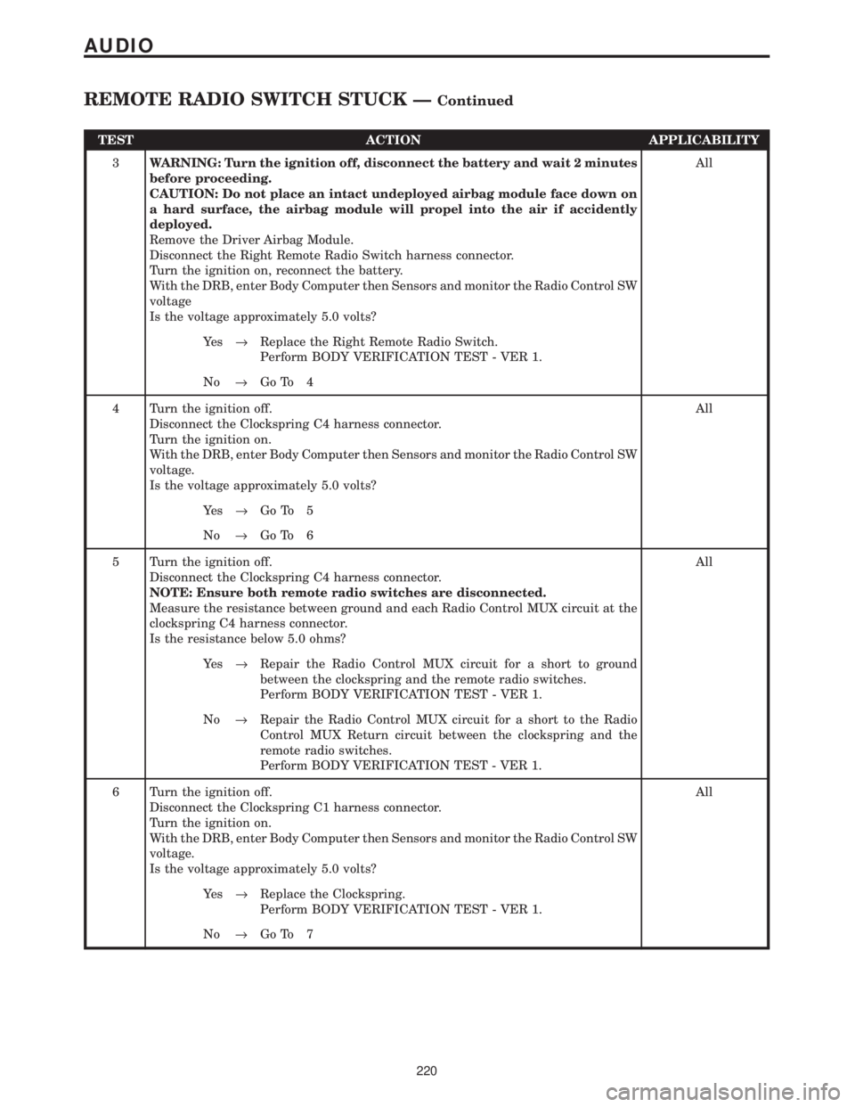
TEST ACTION APPLICABILITY
3WARNING: Turn the ignition off, disconnect the battery and wait 2 minutes
before proceeding.
CAUTION: Do not place an intact undeployed airbag module face down on
a hard surface, the airbag module will propel into the air if accidently
deployed.
Remove the Driver Airbag Module.
Disconnect the Right Remote Radio Switch harness connector.
Turn the ignition on, reconnect the battery.
With the DRB, enter Body Computer then Sensors and monitor the Radio Control SW
voltage
Is the voltage approximately 5.0 volts?All
Ye s®Replace the Right Remote Radio Switch.
Perform BODY VERIFICATION TEST - VER 1.
No®Go To 4
4 Turn the ignition off.
Disconnect the Clockspring C4 harness connector.
Turn the ignition on.
With the DRB, enter Body Computer then Sensors and monitor the Radio Control SW
voltage.
Is the voltage approximately 5.0 volts?All
Ye s®Go To 5
No®Go To 6
5 Turn the ignition off.
Disconnect the Clockspring C4 harness connector.
NOTE: Ensure both remote radio switches are disconnected.
Measure the resistance between ground and each Radio Control MUX circuit at the
clockspring C4 harness connector.
Is the resistance below 5.0 ohms?All
Ye s®Repair the Radio Control MUX circuit for a short to ground
between the clockspring and the remote radio switches.
Perform BODY VERIFICATION TEST - VER 1.
No®Repair the Radio Control MUX circuit for a short to the Radio
Control MUX Return circuit between the clockspring and the
remote radio switches.
Perform BODY VERIFICATION TEST - VER 1.
6 Turn the ignition off.
Disconnect the Clockspring C1 harness connector.
Turn the ignition on.
With the DRB, enter Body Computer then Sensors and monitor the Radio Control SW
voltage.
Is the voltage approximately 5.0 volts?All
Ye s®Replace the Clockspring.
Perform BODY VERIFICATION TEST - VER 1.
No®Go To 7
220
AUDIO
REMOTE RADIO SWITCH STUCK ÐContinued
Page 250 of 4284
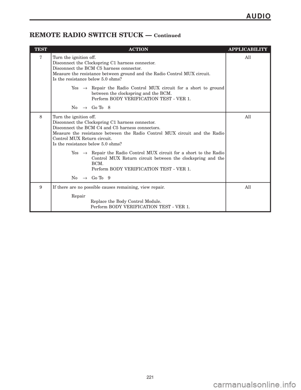
TEST ACTION APPLICABILITY
7 Turn the ignition off.
Disconnect the Clockspring C1 harness connector.
Disconnect the BCM C5 harness connector.
Measure the resistance between ground and the Radio Control MUX circuit.
Is the resistance below 5.0 ohms?All
Ye s®Repair the Radio Control MUX circuit for a short to ground
between the clockspring and the BCM.
Perform BODY VERIFICATION TEST - VER 1.
No®Go To 8
8 Turn the ignition off.
Disconnect the Clockspring C1 harness connector.
Disconnect the BCM C4 and C5 harness connectors.
Measure the resistance between the Radio Control MUX circuit and the Radio
Control MUX Return circuit.
Is the resistance below 5.0 ohms?All
Ye s®Repair the Radio Control MUX circuit for a short to the Radio
Control MUX Return circuit between the clockspring and the
BCM.
Perform BODY VERIFICATION TEST - VER 1.
No®Go To 9
9 If there are no possible causes remaining, view repair. All
Repair
Replace the Body Control Module.
Perform BODY VERIFICATION TEST - VER 1.
221
AUDIO
REMOTE RADIO SWITCH STUCK ÐContinued
Page 275 of 4284

Symptom List:
FRONT IR SENSOR NOT CALIBRATED (ACTIVE)
FRONT KEYBOARD FAULT (ACTIVE)
Test Note: All symptoms listed above are diagnosed using the same tests.
The title for the tests will be FRONT IR SENSOR NOT
CALIBRATED (ACTIVE).
When Monitored and Set Condition:
FRONT IR SENSOR NOT CALIBRATED (ACTIVE)
When Monitored: With the ignition on and the IOD fuse installed.
Set Condition: This DTC is set if the ATC cannot read the IR sensor values or the IR
sensor values are not within a defined range of the HVAC air door motor counts.
POSSIBLE CAUSES
ATC - PROTECTED IGNITION CIRCUIT FAULT
KDB 2 CLOCK CIRCUIT SHORTED TO VOLTAGE
KDB 2 DATA CIRCUIT SHORTED TO GROUND
KDB 2 DATA CIRCUIT SHORTED TO VOLTAGE
PROTECTED IGNITION CIRCUIT OPEN
SENSOR RETURN CIRCUIT OPEN
KDB 2 CLOCK CIRCUIT SHORTED TO GROUND
KDB 2 DATA CIRCUIT OPEN
ATC - KDB 2 DATA CIRCUIT FAULT
ATC - SENSOR RETURN CIRCUIT FAULT
KDB 2 CLOCK CIRCUIT OPEN
ATC - KDB 2 CLOCK CIRCUIT FAULT
ATC REMOTE SENSOR
TEST ACTION APPLICABILITY
1 Turn the ignition off.
Disconnect the ATC Remote Sensor harness connector.
Turn the ignition on.
Measure the voltage of the Protected Ignition circuit.
Is the voltage above 10.0 volts?All
Ye s®Go To 2
No®Go To 16
246
AUTOMATIC TEMPERATURE CONTROL