2001 CHRYSLER VOYAGER check engine light
[x] Cancel search: check engine lightPage 1431 of 4284
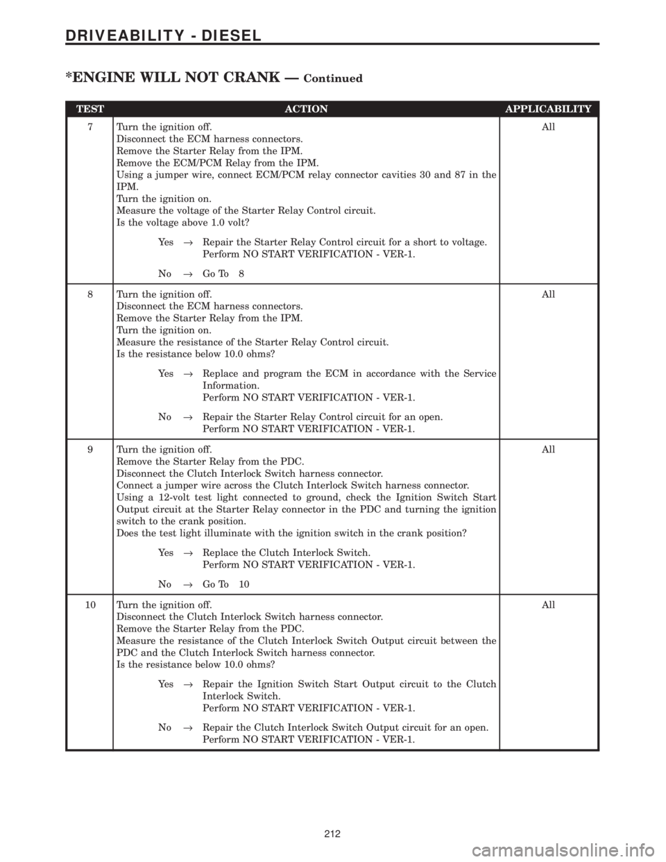
TEST ACTION APPLICABILITY
7 Turn the ignition off.
Disconnect the ECM harness connectors.
Remove the Starter Relay from the IPM.
Remove the ECM/PCM Relay from the IPM.
Using a jumper wire, connect ECM/PCM relay connector cavities 30 and 87 in the
IPM.
Turn the ignition on.
Measure the voltage of the Starter Relay Control circuit.
Is the voltage above 1.0 volt?All
Ye s®Repair the Starter Relay Control circuit for a short to voltage.
Perform NO START VERIFICATION - VER-1.
No®Go To 8
8 Turn the ignition off.
Disconnect the ECM harness connectors.
Remove the Starter Relay from the IPM.
Turn the ignition on.
Measure the resistance of the Starter Relay Control circuit.
Is the resistance below 10.0 ohms?All
Ye s®Replace and program the ECM in accordance with the Service
Information.
Perform NO START VERIFICATION - VER-1.
No®Repair the Starter Relay Control circuit for an open.
Perform NO START VERIFICATION - VER-1.
9 Turn the ignition off.
Remove the Starter Relay from the PDC.
Disconnect the Clutch Interlock Switch harness connector.
Connect a jumper wire across the Clutch Interlock Switch harness connector.
Using a 12-volt test light connected to ground, check the Ignition Switch Start
Output circuit at the Starter Relay connector in the PDC and turning the ignition
switch to the crank position.
Does the test light illuminate with the ignition switch in the crank position?All
Ye s®Replace the Clutch Interlock Switch.
Perform NO START VERIFICATION - VER-1.
No®Go To 10
10 Turn the ignition off.
Disconnect the Clutch Interlock Switch harness connector.
Remove the Starter Relay from the PDC.
Measure the resistance of the Clutch Interlock Switch Output circuit between the
PDC and the Clutch Interlock Switch harness connector.
Is the resistance below 10.0 ohms?All
Ye s®Repair the Ignition Switch Start Output circuit to the Clutch
Interlock Switch.
Perform NO START VERIFICATION - VER-1.
No®Repair the Clutch Interlock Switch Output circuit for an open.
Perform NO START VERIFICATION - VER-1.
212
DRIVEABILITY - DIESEL
*ENGINE WILL NOT CRANK ÐContinued
Page 1432 of 4284
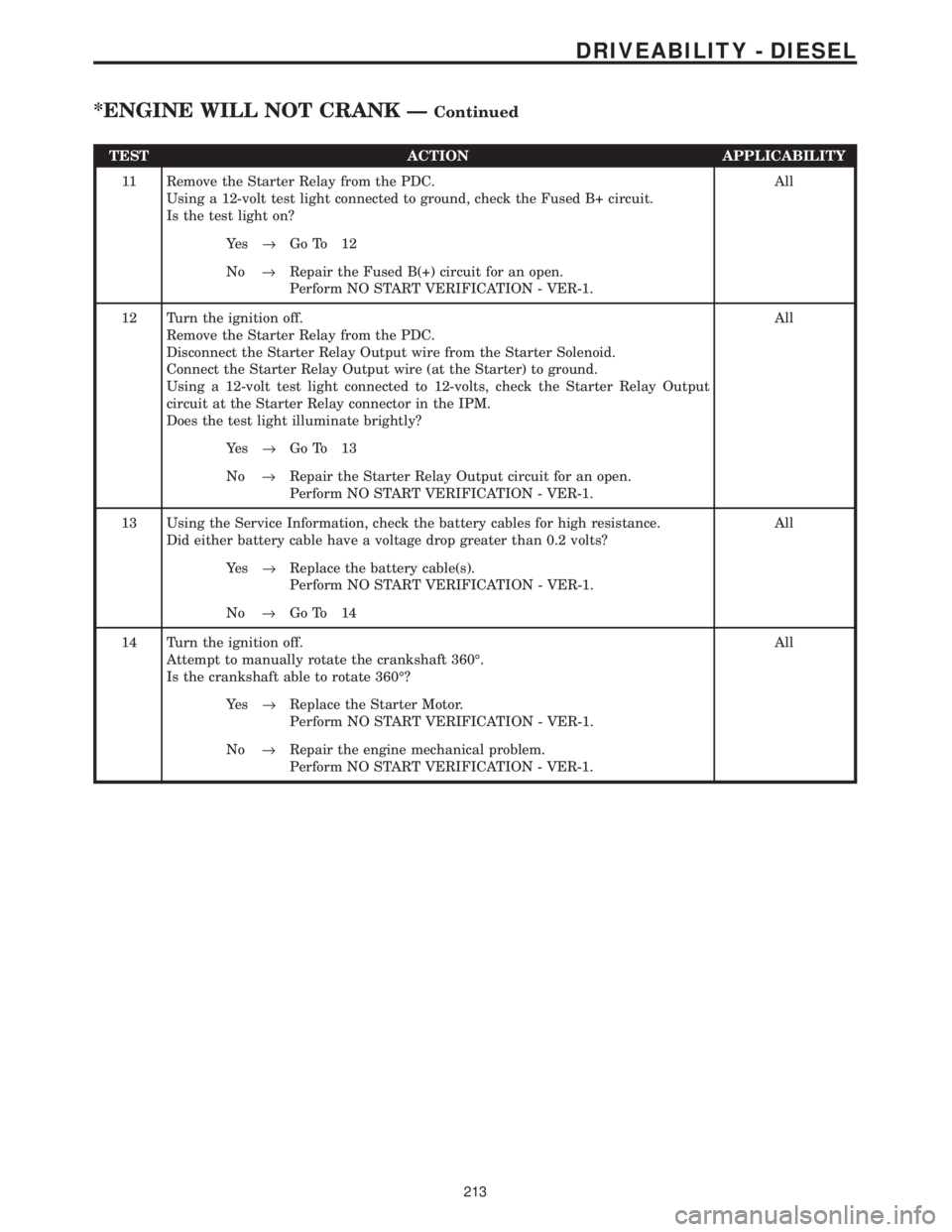
TEST ACTION APPLICABILITY
11 Remove the Starter Relay from the PDC.
Using a 12-volt test light connected to ground, check the Fused B+ circuit.
Is the test light on?All
Ye s®Go To 12
No®Repair the Fused B(+) circuit for an open.
Perform NO START VERIFICATION - VER-1.
12 Turn the ignition off.
Remove the Starter Relay from the PDC.
Disconnect the Starter Relay Output wire from the Starter Solenoid.
Connect the Starter Relay Output wire (at the Starter) to ground.
Using a 12-volt test light connected to 12-volts, check the Starter Relay Output
circuit at the Starter Relay connector in the IPM.
Does the test light illuminate brightly?All
Ye s®Go To 13
No®Repair the Starter Relay Output circuit for an open.
Perform NO START VERIFICATION - VER-1.
13 Using the Service Information, check the battery cables for high resistance.
Did either battery cable have a voltage drop greater than 0.2 volts?All
Ye s®Replace the battery cable(s).
Perform NO START VERIFICATION - VER-1.
No®Go To 14
14 Turn the ignition off.
Attempt to manually rotate the crankshaft 360É.
Is the crankshaft able to rotate 360É?All
Ye s®Replace the Starter Motor.
Perform NO START VERIFICATION - VER-1.
No®Repair the engine mechanical problem.
Perform NO START VERIFICATION - VER-1.
213
DRIVEABILITY - DIESEL
*ENGINE WILL NOT CRANK ÐContinued
Page 1492 of 4284
CONTAINER IDENTIFICATION
Standard engine oil identification notations have
been adopted to aid in the proper selection of engine
oil. The identifying notations are located on the label
of engine oil plastic bottles and the top of engine oil
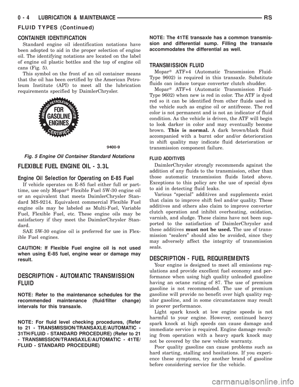
cans (Fig. 5).
This symbol on the front of an oil container means
that the oil has been certified by the American Petro-
leum Institute (API) to meet all the lubrication
requirements specified by DaimlerChrysler.
FLEXIBLE FUEL ENGINE OIL - 3.3L
Engine Oil Selection for Operating on E-85 Fuel
If vehicle operates on E-85 fuel either full or part-
time, use only MopartFlexible Fuel 5W-30 engine oil
or an equivalent that meets DaimlerChrysler Stan-
dard MS-9214. Equivalent commercial Flexible Fuel
engine oils may be labeled as Multi-Fuel, Variable
Fuel, Flexible Fuel, etc. These engine oils may be
satisfactory if they meet the DaimlerChrysler Stan-
dard.
SAE 5W-30 engine oil is preferred for use in Flex-
ible Fuel engines.
CAUTION: If Flexible Fuel engine oil is not used
when using E-85 fuel, engine wear or damage may
result.
DESCRIPTION - AUTOMATIC TRANSMISSION
FLUID
NOTE: Refer to the maintenance schedules for the
recommended maintenance (fluid/filter change)
intervals for this transaxle.
NOTE: For fluid level checking procedures, (Refer
to 21 - TRANSMISSION/TRANSAXLE/AUTOMATIC -
31TH/FLUID - STANDARD PROCEDURE) (Refer to 21
- TRANSMISSION/TRANSAXLE/AUTOMATIC - 41TE/
FLUID - STANDARD PROCEDURE)NOTE: The 41TE transaxle has a common transmis-
sion and differential sump. Filling the transaxle
accommodates the differential as well.
TRANSMISSION FLUID
MopartATF+4 (Automatic Transmission Fluid-
Type 9602) is required in this transaxle. Substitute
fluids can induce torque converter clutch shudder.
MopartATF+4 (Automatic Transmission Fluid-
Type 9602) when new is red in color. The ATF is dyed
red so it can be identified from other fluids used in
the vehicle such as engine oil or antifreeze. The red
color is not permanent and is not an indicator of fluid
condition. As the vehicle is driven, the ATF will begin
to look darker in color and may eventually become
brown.This is normal.A dark brown/black fluid
accompanied with a burnt odor and/or deterioration
in shift quality may indicate fluid deterioration or
transmission component failure.
FLUID ADDITIVES
DaimlerChrysler strongly recommends against the
addition of any fluids to the transmission, other than
those automatic transmission fluids listed above.
Exceptions to this policy are the use of special dyes
to aid in detecting fluid leaks.
Various ªspecialº additives and supplements exist
that claim to improve shift feel and/or quality. These
additives and others also claim to improve converter
clutch operation and inhibit overheating, oxidation,
varnish, and sludge. These claims have not been sup-
ported to the satisfaction of DaimlerChrysler and
these additivesmust not be used.The use of trans-
mission ªsealersº should also be avoided, since they
may adversely affect the integrity of transmission
seals.
DESCRIPTION - FUEL REQUIREMENTS
Your engine is designed to meet all emissions reg-
ulations and provide excellent fuel economy and per-
formance when using high quality unleaded gasoline
having an octane rating of 87. The use of premium
gasoline is not recommended. The use of premium
gasoline will provide no benefit over high quality reg-
ular gasoline, and in some circumstances may result
in poorer performance.
Light spark knock at low engine speeds is not
harmful to your engine. However, continued heavy
spark knock at high speeds can cause damage and
immediate service is required. Engine damage result-
ing from operation with a heavy spark knock may
not be covered by the new vehicle warranty.
Poor quality gasoline can cause problems such as
hard starting, stalling and hesitations. If you experi-
ence these symptoms, try another brand of gasoline
before considering service for the vehicle.
Fig. 5 Engine Oil Container Standard Notations
0 - 4 LUBRICATION & MAINTENANCERS
FLUID TYPES (Continued)
Page 1493 of 4284
Over 40 auto manufacturers world-wide have
issued and endorsed consistent gasoline specifications
(the Worldwide Fuel Charter, WWFC) to define fuel
properties necessary to deliver enhanced emissions,
performance and durability for your vehicle. We rec-
ommend the use of gasolines that meet the WWFC
specifications if they are available.
REFORMULATED GASOLINE
Many areas of the country require the use of
cleaner burning gasoline referred to as ªreformulat-
edº gasoline. Reformulated gasoline contain oxygen-
ates, and are specifically blended to reduce vehicle
emissions and improve air quality.
We strongly supports the use of reformulated gas-
oline. Properly blended reformulated gasoline will
provide excellent performance and durability for the
engine and fuel system components.
GASOLINE/OXYGENATE BLENDS
Some fuel suppliers blend unleaded gasoline with
oxygenates such as 10% ethanol, MTBE, and ETBE.
Oxygenates are required in some areas of the country
during the winter months to reduce carbon monoxide
emissions. Fuels blended with these oxygenates may
be used in your vehicle.
CAUTION: DO NOT use gasoline containing METH-
ANOL. Gasoline containing methanol may damage
critical fuel system components.
MMT IN GASOLINE
MMT is a manganese-containing metallic additive
that is blended into some gasoline to increase octane.
Gasoline blended with MMT provide no performance
advantage beyond gasoline of the same octane num-
ber without MMT. Gasoline blended with MMT
reduce spark plug life and reduce emission system
performance in some vehicles. We recommend that
gasolines free of MMT be used in your vehicle. The
MMT content of gasoline may not be indicated on the
gasoline pump; therefore, you should ask your gaso-
line retailer whether or not his/her gasoline contains
MMT.
It is even more important to look for gasoline with-
out MMT in Canada because MMT can be used at
levels higher than allowed in the United States.
MMT is prohibited in Federal and California refor-
mulated gasoline.
SULFUR IN GASOLINE
If you live in the northeast United States, your
vehicle may have been designed to meet California
low emission standards with Cleaner-Burning Cali-
fornia reformulated gasoline with low sulfur. If such
fuels are not available in states adopting Californiaemission standards, your vehicles will operate satis-
factorily on fuels meeting federal specifications, but
emission control system performance may be
adversely affected. Gasoline sold outside of California
is permitted to have higher sulfur levels which may
affect the performance of the vehicle's catalytic con-
verter. This may cause the Malfunction Indicator
Lamp (MIL), Check Engine or Service Engine Soon
light to illuminate. We recommend that you try a dif-
ferent brand of unleaded gasoline having lower sulfur
to determine if the problem is fuel related prior to
returning your vehicle to an authorized dealer for
service.
CAUTION: If the Malfunction Indicator Lamp (MIL),
Check Engine or Service Engine Soon light is flash-
ing, immediate service is required; see on-board
diagnostics system section.
MATERIALS ADDED TO FUEL
All gasoline sold in the United States and Canada
are required to contain effective detergent additives.
Use of additional detergents or other additives is not
needed under normal conditions.
FUEL SYSTEM CAUTIONS
CAUTION: Follow these guidelines to maintain your
vehicle's performance:
²The use of leaded gas is prohibited by Federal
law. Using leaded gasoline can impair engine perfor-
mance, damage the emission control system, and
could result in loss of warranty coverage.
²An out-of-tune engine, or certain fuel or ignition
malfunctions, can cause the catalytic converter to
overheat. If you notice a pungent burning odor or
some light smoke, your engine may be out of tune or
malfunctioning and may require immediate service.
Contact your dealer for service assistance.
²When pulling a heavy load or driving a fully
loaded vehicle when the humidity is low and the tem-
perature is high, use a premium unleaded fuel to
help prevent spark knock. If spark knock persists,
lighten the load, or engine piston damage may result.
²The use of fuel additives which are now being
sold as octane enhancers is not recommended. Most
of these products contain high concentrations of
methanol. Fuel system damage or vehicle perfor-
mance problems resulting from the use of such fuels
or additives is not the responsibility of Daimler-
Chrysler Corporation and may not be covered under
the new vehicle warranty.
RSLUBRICATION & MAINTENANCE0-5
FLUID TYPES (Continued)
Page 1495 of 4284
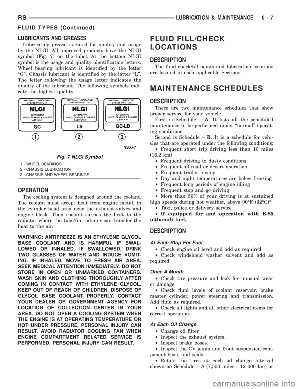
LUBRICANTS AND GREASES
Lubricating grease is rated for quality and usage
by the NLGI. All approved products have the NLGI
symbol (Fig. 7) on the label. At the bottom NLGI
symbol is the usage and quality identification letters.
Wheel bearing lubricant is identified by the letter
ªGº. Chassis lubricant is identified by the latter ªLº.
The letter following the usage letter indicates the
quality of the lubricant. The following symbols indi-
cate the highest quality.
OPERATION
The cooling system is designed around the coolant.
The coolant must accept heat from engine metal, in
the cylinder head area near the exhaust valves and
engine block. Then coolant carries the heat to the
radiator where the tube/fin radiator can transfer the
heat to the air.
WARNING: ANTIFREEZE IS AN ETHYLENE GLYCOL
BASE COOLANT AND IS HARMFUL IF SWAL-
LOWED OR INHALED. IF SWALLOWED, DRINK
TWO GLASSES OF WATER AND INDUCE VOMIT-
ING. IF INHALED, MOVE TO FRESH AIR AREA.
SEEK MEDICAL ATTENTION IMMEDIATELY. DO NOT
STORE IN OPEN OR UNMARKED CONTAINERS.
WASH SKIN AND CLOTHING THOROUGHLY AFTER
COMING IN CONTACT WITH ETHYLENE GLYCOL.
KEEP OUT OF REACH OF CHILDREN. DISPOSE OF
GLYCOL BASE COOLANT PROPERLY, CONTACT
YOUR DEALER OR GOVERNMENT AGENCY FOR
LOCATION OF COLLECTION CENTER IN YOUR
AREA. DO NOT OPEN A COOLING SYSTEM WHEN
THE ENGINE IS AT OPERATING TEMPERATURE OR
HOT UNDER PRESSURE, PERSONAL INJURY CAN
RESULT. AVOID RADIATOR COOLING FAN WHEN
ENGINE COMPARTMENT RELATED SERVICE IS
PERFORMED, PERSONAL INJURY CAN RESULT.
FLUID FILL/CHECK
LOCATIONS
DESCRIPTION
The fluid check/fill points and lubrication locations
are located in each applicable Sections.
MAINTENANCE SCHEDULES
DESCRIPTION
There are two maintenance schedules that show
proper service for your vehicle.
First is Schedule ±A. It lists all the scheduled
maintenance to be performed under ªnormalº operat-
ing conditions.
Second is Schedule ±B. It is a schedule for vehi-
cles that are operated under the following conditions:
²Frequent short trip driving less than 10 miles
(16.2 km)
²Frequent driving in dusty conditions
²Frequent off-road or desert operation
²Frequent trailer towing
²Day and night temperatures are below freezing
²Frequent long periods of engine idling
²Frequent stop and go driving
²More than 50% of your driving is at sustained
high speeds during hot weather, above 90ÉF (32ÉC)*
²Taxi, police or delivery service
²If equipped for and operation with E-85
(ethanol) fuel.
DESCRIPTION
At Each Stop For Fuel
²Check engine oil level and add as required.
²Check windshield washer solvent and add as
required.
Once A Month
²Check tire pressure and look for unusual wear
or damage.
²Check fluid levels of coolant reservoir, brake
master cylinder, power steering and transmission.
Add fluid as required.
²Check all lights and all other electrical items for
correct operation.
At Each Oil Change
²Change oil filter
²Inspect the exhaust system.
²Inspect brake hoses.
²Inspect the CV joints and front suspension com-
ponent boots and seals.
²Rotate the tires at each oil change interval
shown on Schedule ± A (7,500 miles - 12 000 km) or
Fig. 7 NLGI Symbol
1 - WHEEL BEARINGS
2 - CHASSIS LUBRICATION
3 - CHASSIS AND WHEEL BEARINGS
RSLUBRICATION & MAINTENANCE0-7
FLUID TYPES (Continued)
Page 1511 of 4284
FLUID FILL/CHECK
LOCATIONS
DESCRIPTION
The fluid check/fill points and lubrication locations
are located in each applicable service manual section.
MAINTENANCE SCHEDULES
MAINTENANCE SCHEDULES - DIESEL ENGINE
There are two maintenance schedules that show
proper service for the vehicle.
First is ScheduleªAº. It lists all the scheduled
maintenance to be performed under ªnormalº operat-
ing conditions.
Second is ScheduleªBº. It is a schedule for vehi-
cles that are operated under the conditions listed at
the beginning of the schedule.
Use the schedule that best describes the driving
conditions.
Where time and mileage are listed, follow the
interval that occurs first.
At Each Stop for Fuel
²Check the engine oil level, add as required.
²Check the windshield washer solvent and add if
required.
Once a Month
²Check the tire pressure and look for unusual
wear or damage.
²Inspect the battery and clean and tighten termi-
nals as required.
²Check the fluid levels of coolant reservoir, brake
master cylinder, power steering and transaxle and
add as needed.
²Check all lights and all other electrical items for
correct operation.
²Check the rubber seals on each side of the radi-
ator for proper fit.
At Each Oil Change
²Replace the engine oil filter at each oil change.
²Inspect exhaust system.
²Inspect brake hoses
²Inspect the CV joints and front suspension com-
ponents
²Rotate the tires at each oil change interval
shown on schedule ªAº 20 000 km or every other
interval shown on schedule ªBº 20 000 km.
²Check the coolant level, hoses, and clamps.
²Inspect brake linings, hoses and calipers.
²Inspect engine accessory drive belts.
²Inspect for presence of water in fuel filter/water
separator, drain if necessary.
SCHEDULE ªAº
20 000 km (12 000 miles)
²Change engine oil. (1)
²Replace engine oil filter.
²Inspect air filter element. Replace as necessary.
40 000 km (24 000 Miles)
²Change engine oil. (1)
²Replace engine oil filter.
²Replace air filter element.
²Replace fuel filter/water separator element. (2)
²Check alignment.
60 000 km (37 000 Miles)
²Change engine oil. (1)
²Replace engine oil filter.
²Inspect air filter element. Replace as necessary.
80 000 km (49 000 Miles)
²Change engine oil. (1)
²Replace engine oil filter.
²Replace air filter element.
²Replace fuel filter/water separator element. (2)
²Check alignment.
100 000 km (62 000 Miles)
²Change engine oil. (1)
²Replace engine oil filter.
²Inspect air filter element. Replace as necessary.
120 000 km (75 000 Miles)
²Change engine oil. (1)
²Replace engine oil filter.
²Replace air filter element.
²Replace fuel filter/water separator element. (2)
²Check alignment.
140 000 km (86 000 miles)
²Change engine oil. (1)
²Replace engine oil filter.
²Inspect air filter element. Replace as necessary.
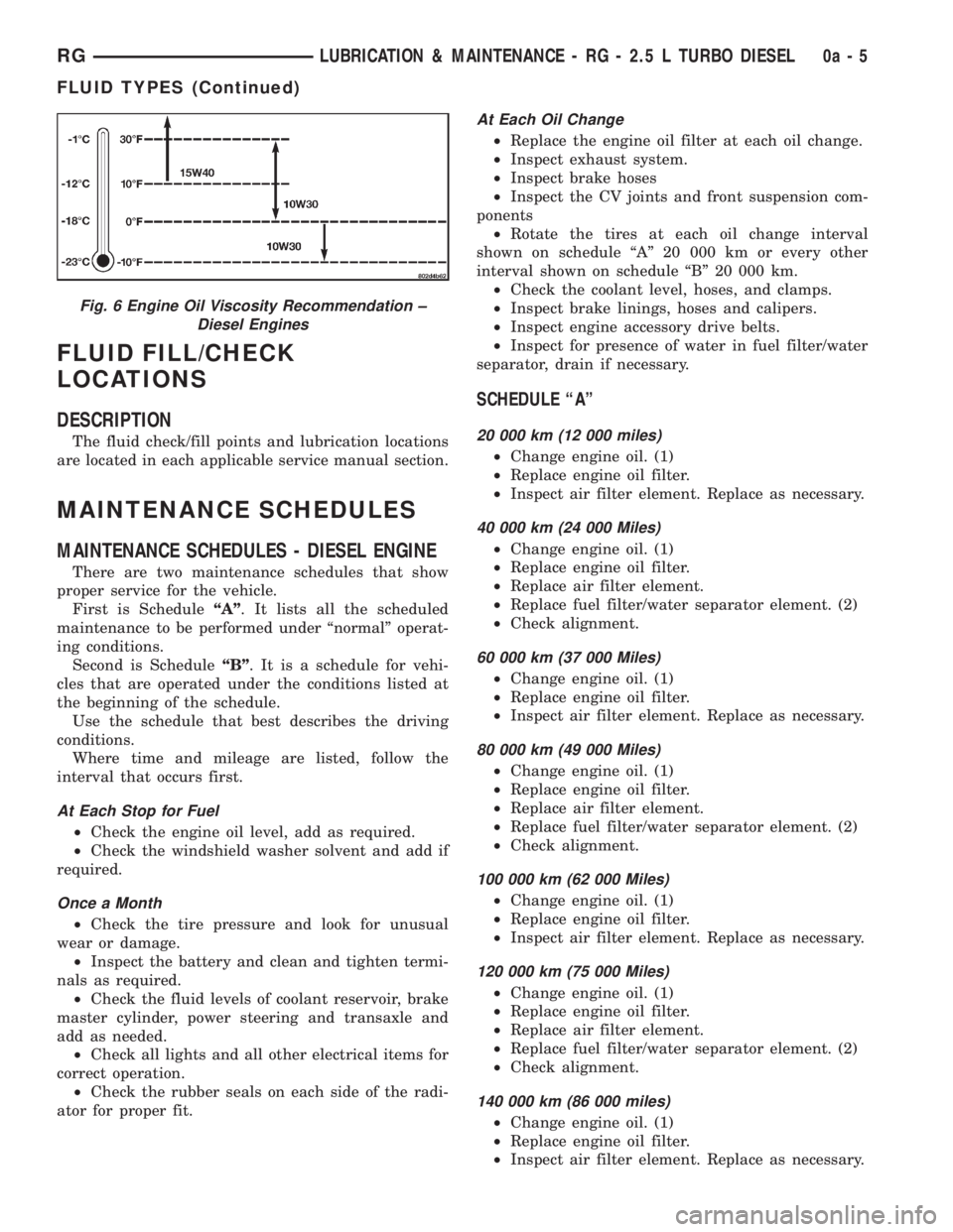
Fig. 6 Engine Oil Viscosity Recommendation ±
Diesel Engines
RGLUBRICATION & MAINTENANCE - RG - 2.5 L TURBO DIESEL0a-5
FLUID TYPES (Continued)
Page 1664 of 4284
DIAGNOSIS AND TESTING - POWER BRAKE
BOOSTER
BASIC TEST
(1) With engine off, depress and release the brake
pedal several times to purge all vacuum from the
power brake booster.
(2) Depress and hold the pedal with light effort (15
to 25 lbs. pressure), then start the engine.
The pedal should fall slightly, then hold. Less effort
should be needed to apply the pedal at this time. If
the pedal fell as indicated, perform the VACUUM
LEAK TEST listed after the BASIC TEST. If the
pedal did not fall, continue on with this BASIC TEST.
(3) Disconnect the vacuum hose on the vacuum
check valve, then place a vacuum gauge in line
between the vacuum hose and the valve.
(4) Start the engine.
(5) When the engine is at warm operating temper-
ature, allow it to idle and check the vacuum at the
gauge.
If the vacuum supply is 12 inches Hg (40.5 kPa) or
more, the power brake booster is defective and must
be replaced. If the vacuum supply is below 12 inches
Hg, continue on with this BASIC TEST.
(6) Shut off the engine.
(7) Connect the vacuum gauge to the vacuum ref-
erence port on the engine intake manifold.
(8) Start the engine and observe the vacuum
gauge.
If the vacuum is still low, check the engine tune
and repair as necessary. If the vacuum is above 12
inches Hg, the hose or check valve to the booster has
a restriction or leak.
Once an adequate vacuum supply is obtained,
repeat the BASIC TEST.
VACUUM LEAK TEST
(1) Disconnect the vacuum hose on the vacuum
check valve, then place a vacuum gauge in line
between the vacuum hose and the valve.
(2) Start the engine.
(3) Allow the engine to warm up to normal operat-
ing temperature and engine idle.
(4) Using vacuum line pliers, close off the vacuum
supply hose near the booster, but before the vacuum
gauge, then observe the vacuum gauge.
If the vacuum drop exceeds 1.0 inch Hg (3.3 kPa)
in one minute, repeat the above steps to confirm the
reading. The vacuum loss should be less than 1.0
inch Hg in one minute time span. If the loss is more
than 1.0 inch Hg, replace the power brake booster. If
it is not, continue on with this test.
(5) Remove the pliers from the hose temporarily.
(6) Apply light effort (approximately 15 lbs. of
force) to the brake pedal and hold the pedal steady.Do not move the pedal once the pressure is applied
or the test results may vary.
(7) Have an assistant reattach the vacuum line
pliers to the vacuum supply hose.
(8) Allow 5 seconds for stabilization, then observe
the vacuum gauge.
If the vacuum drop exceeds 3.0 inches Hg (10 kPa)
in 15 seconds, repeat the above steps to confirm the
reading. The vacuum loss should be less than 3.0
inches Hg in 15 seconds time span. If the loss is
more than 3.0 inches Hg, replace the power brake
booster. If it is not, the booster is not defective.
(9) Remove the pliers and vacuum gauge.
REMOVAL - POWER BRAKE BOOSTER
CAUTION: Reserve vacuum in power brake booster
must be pumped down (removed) before removing
master cylinder from booster. This is necessary to
prevent booster from sucking in any contamination
as master cylinder is removed. This can be done
simply by pumping the brake pedal, with the vehi-
cle's engine not running, until a firm feeling brake
pedal is achieved.
(1) With engine not running, pump the brake
pedal until a firm pedal is achieved (4-5 strokes).
(2) Remove negative battery cable terminal from
battery.
(3) Remove positive battery cable terminal from
battery.
(4) Remove battery thermal guard shield.
(5) Remove battery clamp, nut and battery from
the battery tray.
(6) Remove screw securing engine coolant filler
tube to battery tray.
(7) If the vehicle is equipped with speed control,
disconnect the vacuum hose at the vacuum tank built
into the battery tray.
(8) Remove the two nuts and one bolt securing bat-
tery tray in place. Remove battery tray.
(9) If vehicle is equipped with speed control:
(a) Disconnect wiring harness connector from
the speed control servo.
(b) Remove the two servo mounting nuts.
(c) Lay speed control servo off to the side, out of
the way.
(10) Remove the wiper module (unit). (Refer to 8 -
ELECTRICAL/WIPERS/WASHERS/WIPER MOD-
ULE - REMOVAL)
(11) Disconnect wiring harness connector from
brake fluid level switch in master cylinder fluid res-
ervoir (Fig. 54).
5 - 38 BRAKES - BASERS
POWER BRAKE BOOSTER (Continued)
Page 1666 of 4284

(19) Rotate screwdriver enough to allow retaining
clip center tang to pass over end of brake pedal pin.
Then pull retaining clip off brake pedal pin.Discard
retaining clip. It is not to be reused. Replace
only with a new retaining clip when assem-
bling.
(20) Slide booster input rod off pedal pin.
(21) Remove the four nuts attaching power brake
booster to dash panel (Fig. 57).
(22) Slide power brake booster forward and remove
through engine compartment (Fig. 58).
CAUTION: Do not attempt to disassemble the power
brake vacuum booster it is serviced ONLY as a
complete assembly.INSTALLATION - POWER BRAKE BOOSTER
(1) Position power brake booster on dash panel
using the reverse procedure of its removal (Fig. 58).
It may be necessary to push in on booster input rod
as it is guided through the dash panel.
(2) Install the four nuts mounting the booster to
the dash panel (Fig. 57). Tighten the mounting nuts
to a torque of 29 N´m (250 in. lbs.).
(3) Using lubriplate, or equivalent, coat the sur-
face of the brake pedal pin where it contacts the
booster input rod.
CAUTION: When installing the brake pedal pin on
the power brake booster input rod, do not re-use
the old retaining clip.
(4) Install booster input rod on brake pedal pin
and install a NEW retaining clip (Fig. 59).
CAUTION: Do not reuse the original brake lamp
switch. The switch can only be adjusted once. That
is during initial installation of the switch. If the
switch is not adjusted properly or has been
removed for some service, a new switch must be
installed and adjusted.
(5) Remove and replace the brake lamp switch
with a NEW switch. (Refer to 8 - ELECTRICAL/
LAMPS/LIGHTING - EXTERIOR/BRAKE LAMP
SWITCH - REMOVAL), (Refer to 8 - ELECTRICAL/
LAMPS/LIGHTING - EXTERIOR/BRAKE LAMP
SWITCH - INSTALLATION)
(6) Install the silencer panel below the steering
column.
(7) Connect vacuum hose to check valve on power
brake booster.
Fig. 57 BOOSTER MOUNTING
1 - DASH BRACKET
2 - POWER BRAKE BOOSTER
3 - BRAKE PEDAL ASSEMBLY
Fig. 58 BOOSTER REMOVAL/INSTALLATION
Fig. 59 Retaining Pin Installed On Brake Pedal Pin
1 - BRAKE PEDAL
2 - RETAINING CLIP
3 - BOOSTER INPUT ROD
5 - 40 BRAKES - BASERS
POWER BRAKE BOOSTER (Continued)