2001 CHRYSLER VOYAGER jump start
[x] Cancel search: jump startPage 1884 of 4284
(5) Connect a remote starter switch or a jumper
wire between the remote battery positive post and
terminal 87 of the starter relay connector.
(a) If engine cranks, starter/starter solenoid is
good. Go to the Starter Relay Test.
(b) If engine does not crank or solenoid chatters,
check wiring and connectors from starter relay to
starter solenoid for loose or corroded connections.
Particularly at starter terminals.
(c) Repeat test. If engine still fails to crank prop-
erly, trouble is within starter or starter mounted
solenoid, and replace starter.
STARTER RELAY
WARNING: CHECK TO ENSURE THAT THE TRANS-
MISSION IS IN THE PARK/NEUTRAL POSITION
WITH THE PARKING BRAKE APPLIED.
RELAY TEST
The starter relay is located in the Power Distribu-
tion Center (PDC) in the engine compartment. Refer
to the PDC label for relay identification and location.
Remove the starter relay from the PDC as
described in this group to perform the following tests:
(1) A relay in the de-energized position should
have continuity between terminals 87A and 30, and
no continuity between terminals 87 and 30. If OK, go
to Step 2. If not OK, replace the faulty relay.
(2) Resistance between terminals 85 and 86 (elec-
tromagnet) should be 7565 ohms. If OK, go to Step
3. If not OK, replace the faulty relay.
(3) Connect a battery B+ lead to terminals 86 and
a ground lead to terminal 85 to energize the relay.
The relay should click. Also test for continuity
between terminals 30 and 87, and no continuity
between terminals 87A and 30. If OK, refer to Relay
Circuit Test procedure. If not OK, replace the faulty
relay.
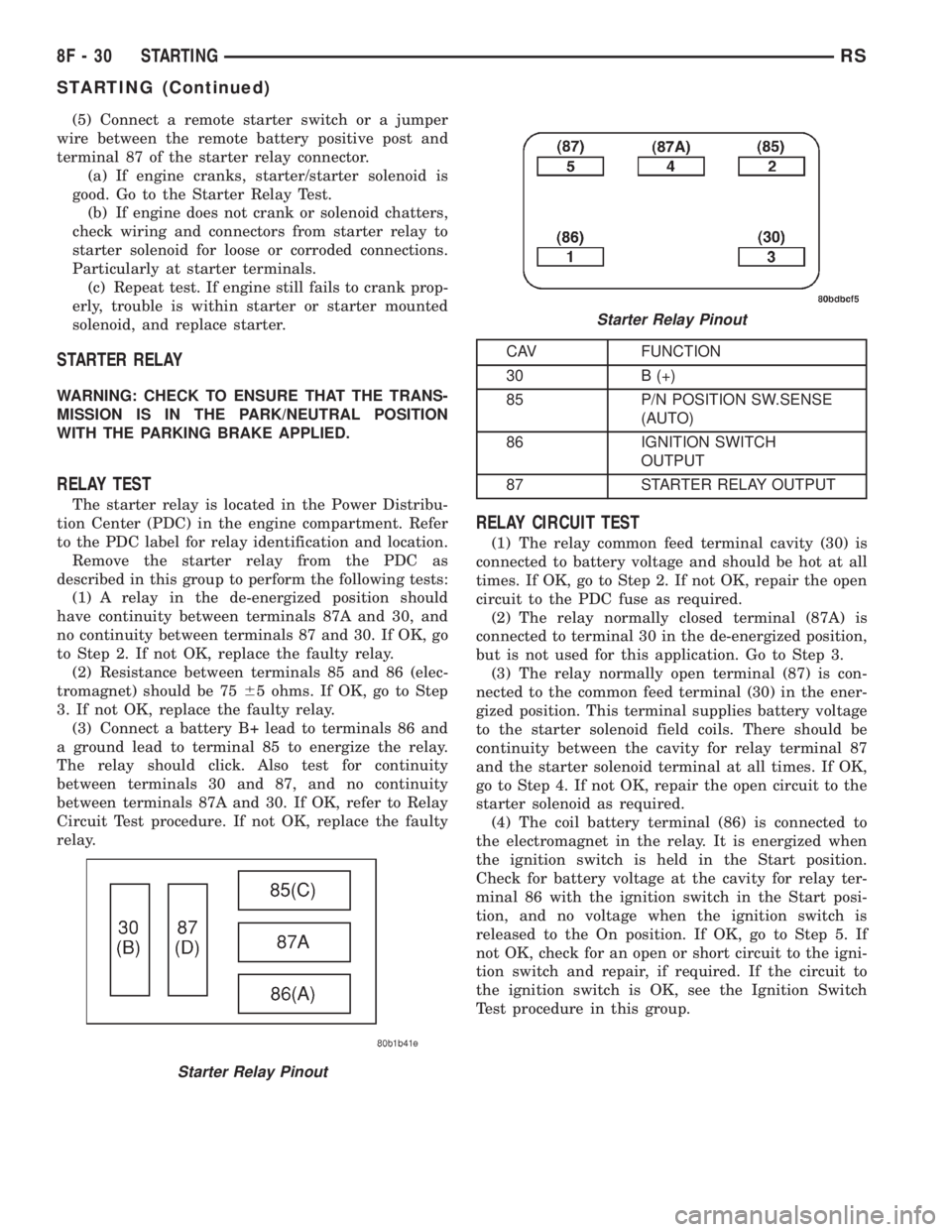
CAV FUNCTION
30 B (+)
85 P/N POSITION SW.SENSE
(AUTO)
86 IGNITION SWITCH
OUTPUT
87 STARTER RELAY OUTPUT
RELAY CIRCUIT TEST
(1) The relay common feed terminal cavity (30) is
connected to battery voltage and should be hot at all
times. If OK, go to Step 2. If not OK, repair the open
circuit to the PDC fuse as required.
(2) The relay normally closed terminal (87A) is
connected to terminal 30 in the de-energized position,
but is not used for this application. Go to Step 3.
(3) The relay normally open terminal (87) is con-
nected to the common feed terminal (30) in the ener-
gized position. This terminal supplies battery voltage
to the starter solenoid field coils. There should be
continuity between the cavity for relay terminal 87
and the starter solenoid terminal at all times. If OK,
go to Step 4. If not OK, repair the open circuit to the
starter solenoid as required.
(4) The coil battery terminal (86) is connected to
the electromagnet in the relay. It is energized when
the ignition switch is held in the Start position.
Check for battery voltage at the cavity for relay ter-
minal 86 with the ignition switch in the Start posi-
tion, and no voltage when the ignition switch is
released to the On position. If OK, go to Step 5. If
not OK, check for an open or short circuit to the igni-
tion switch and repair, if required. If the circuit to
the ignition switch is OK, see the Ignition Switch
Test procedure in this group.
Starter Relay Pinout
Starter Relay Pinout
8F - 30 STARTINGRS
STARTING (Continued)
Page 2103 of 4284
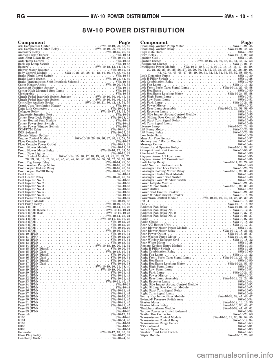
8W-10 POWER DISTRIBUTION
Component PageA/C Compressor Clutch..................8Wa-10-19, 20, 38, 40
A/C Compressor Clutch Relay.............8Wa-10-19, 20, 37, 38, 40
Accessory Relay.......................8Wa-10-15, 26, 57
Ambient Temp Sensor........................8Wa-10-54
Auto Shut Down Relay......................8Wa-10-19, 34
Auto Temp Control.........................8Wa-10-33
Back-Up Lamp Switch........................8Wa-10-58
Battery........................8Wa-10-12, 13, 14, 34, 40
Blower Motor Resistor......................8Wa-10-17, 31
Body Control Module......8Wa-10-21, 33, 38, 41, 42, 44, 46, 47, 48, 49, 61
Brake Fluid Level Switch......................8Wa-10-57
Brake Lamp Switch.....................8Wa-10-21, 44, 59
Brake Transmission Shift Interlock Solenoid.............8Wa-10-55
Cabin Heater Assist.....................8Wa-10-20, 36, 52
Camshaft Position Sensor......................8Wa-10-37
Center High Mounted Stop Lamp..................8Wa-10-59
Clockspring.............................8Wa-10-53
Clutch Pedal Interlock Switch Jumper........8Wa-10-16, 30, 46, 47, 53
Clutch Pedal Interlock Switch............8Wa-10-16, 30, 46, 47, 53
Controller Antilock Brake...........8Wa-10-16, 21, 30, 42, 48, 54, 59
Crank Case Ventilation Heater...................8Wa-10-41
Data Link Connector.......................8Wa-10-29, 61
Defogger Relay......................8Wa-10-17, 18, 32, 56
Diagnostic Junction Port.......................8Wa-10-54
Driver Door Lock Switch.....................8Wa-10-28, 29
Driver Heated Seat Module.....................8Wa-10-42
Driver Power Seat Switch......................8Wa-10-42
Driver Power Window Switch....................8Wa-10-29
ECM/PCM Relay.........................8Wa-10-20, 36
EGR Solenoid..........................8Wa-10-37, 39
Electric Wiper De-Icer........................8Wa-10-28
Engine Control Module........8Wa-10-16, 20, 30, 36, 37, 40, 41, 58, 59
Floor Console Lamp.........................8Wa-10-27
Floor Console Power Outlet...................8Wa-10-27, 29
Front Blower Module......................8Wa-10-17, 31
Front Blower Motor Relay................8Wa-10-16, 17, 31, 56
Front Cigar Lighter.......................8Wa-10-15, 27
Front Control Module . . . 8Wa-10-14, 15, 16, 17, 18, 19, 20, 21, 22, 23, 24, 25,
26, 29, 30, 31, 32, 38, 40, 45, 46, 47, 50, 51, 52, 53, 54. 55, 56, 57, 58, 59, 61
Front Fog Lamp Relay....................8Wa-10-14, 22, 56
Front Washer Pump Motor..................8Wa-10-15, 26, 61
Front Wiper Hi/Low Relay..................8Wa-10-15, 25, 57
Front Wiper On/Off Relay..................8Wa-10-15, 25, 52
Fuel Heater.............................8Wa-10-41
Fuel Heater Relay......................8Wa-10-20, 40, 57
Fuel Injector No. 1..........................8Wa-10-35
Fuel Injector No. 2..........................8Wa-10-35
Fuel Injector No. 3..........................8Wa-10-35
Fuel Injector No. 4..........................8Wa-10-35
Fuel Injector No. 5..........................8Wa-10-35
Fuel Injector No. 6..........................8Wa-10-35
Fuel Pressure Solenoid.......................8Wa-10-37
Fuel Pump Module........................8Wa-10-19, 38
Fuel Pump Relay.......................8Wa-10-19, 38, 57
Fuse 1 (IPM).........................8Wa-10-14, 15, 22
Fuse 2 (IPM) (Diesel).....................8Wa-10-14, 10-24
Fuse 2 (IPM) (Gas)......................8Wa-10-14, 10-23
Fuse 3 (IPM).........................8Wa-10-14, 23, 24
Fuse 4 (IPM).......................8Wa-10-14, 15, 16, 25
Fuse 5 (IPM)...........................8Wa-10-15, 26
Fuse 6 (IPM)...........................8Wa-10-15, 26
Fuse 8 (IPM)...........................8Wa-10-16, 29
Fuse 9 (IPM).........................8Wa-10-16, 17, 30
Fuse 10 (IPM)..........................8Wa-10-17, 31
Fuse 11 (IPM)..........................8Wa-10-15, 26
Fuse 12 (IPM)..........................8Wa-10-17, 31
Fuse 13 (IPM)..........................8Wa-10-18, 32
Fuse 14 (IPM)....................8Wa-10-18, 19, 20, 32, 52
Fuse 15 (IPM) (Diesel)......................8Wa-10-20, 36
Fuse 15 (IPM) (Gas).....................8Wa-10-18, 19, 34
Fuse 16 (IPM) (Diesel)......................8Wa-10-20, 36
Fuse 16 (IPM) (Gas).......................8Wa-10-19, 34
Fuse 17 (IPM) (Diesel)......................8Wa-10-20, 40
Fuse 17 (IPM) (Gas).......................8Wa-10-19, 38
Fuse 18 (IPM)....................8Wa-10-19, 20, 21, 38, 40
Fuse 19 (IPM)......................8Wa-10-19, 20, 21, 42
Fuse 20 (IPM)..........................8Wa-10-21, 42
Fuse 21 (IPM)..........................8Wa-10-21, 42
Fuse 22 (IPM)..........................8Wa-10-21, 42
Fuse 23 (IPM)........................8Wa-10-21, 46, 47
Fuse 24 (IPM)............................8Wa-10-21
Fuse 24 (IPM)............................8Wa-10-44
Fuse 26 (IPM)..........................8Wa-10-21, 44
Fuse 27 (IPM)..........................8Wa-10-21, 44
Fuse 28 (IPM)..........................8Wa-10-15, 26
Fuse 30 (IPM)..........................8Wa-10-21, 45
Fuse 31 (IPM)..........................8Wa-10-21, 45
Fuse 32 (IPM)..........................8Wa-10-21, 45
Fuse 33 (IPM)............................8Wa-10-15
Fuse 33 (IPM)............................8Wa-10-26
Fuselink.............................8Wa-10-12, 13
G100................................8Wa-10-48
G101...............................8Wa-10-34, 40
G103................................8Wa-10-61
G300................................8Wa-10-50
G300................................8Wa-10-51
Generator........................8Wa-10-12, 13, 35, 37
Glow Plug Relay.........................8Wa-10-12, 37
Headlamp Switch........................8Wa-10-24, 55Component PageHeadlamp Washer Pump Motor.................8Wa-10-21, 45
Headlamp Washer Relay...................8Wa-10-21, 45, 56
High Note Horn...........................8Wa-10-29
Horn Relay..........................8Wa-10-16, 29, 52
Ignition Coil.............................8Wa-10-35
Ignition Switch............8Wa-10-16, 21, 30, 38, 39, 41, 46, 47, 53
Instrument Cluster.......................8Wa-10-21, 44
Intelligent Power Module . . 8Wa-10-2, 10-3, 10-4, 10-12, 14, 15, 16, 17, 18, 19,
20, 21, 22, 23, 24, 25, 26, 27, 28, 29, 30, 31, 32, 33, 34, 35, 36, 37, 38, 39, 40,
41, 42, 44, 45, 46, 47, 48, 49, 50, 51, 52, 53, 54, 55, 56, 57, 58, 59, 61
Leak Detection Pump........................8Wa-10-39
Left B-Pillar Switch.........................8Wa-10-28
Left Combination Relay.......................8Wa-10-60
Left Fog Lamp..........................8Wa-10-14, 22
Left Front Park/ Turn Signal Lamp............8Wa-10-14, 23, 49, 58
Left Headlamp............................8Wa-10-50
Left Headlamp Leveling Motor................8Wa-10-24, 55, 58
Left High Beam Lamp........................8Wa-10-51
Left Low Beam Lamp........................8Wa-10-51
Left Park Lamp.........................8Wa-10-24, 58
Left Power Mirror..........................8Wa-10-32
Left Rear Lamp Assembly..............8Wa-10-23, 24, 58, 59, 60
Left Repeater Lamp.........................8Wa-10-44
Left Side Impact Airbag Control Module...............8Wa-10-55
Left Sliding Door Control Module..................8Wa-10-45
Left Stop/ Turn Signal Relay.....................8Wa-10-60
Left Turn Signal Lamp.......................8Wa-10-49
License Lamp........................8Wa-10-23, 24, 58
Lift Pump Motor.........................8Wa-10-20, 36
Lift Pump Relay.........................8Wa-10-20, 36
Low Note Horn...........................8Wa-10-29
Mass Air Flow Sensor........................8Wa-10-37
Memory Seat/ Mirror Module....................8Wa-10-42
Message Center...........................8Wa-10-44
Name Brand Speaker Relay.................8Wa-10-18, 32, 52
Occupant Restraint Controller..................8Wa-10-56, 61
Overhead Console..........................8Wa-10-33
Oxygen Sensor 1/1 Upstream....................8Wa-10-35
Oxygen Sensor 1/2 Downstream...................8Wa-10-35
Park Lamp Relay.....................8Wa-10-14, 23, 24, 52
Park/ Neutral Position Switch....................8Wa-10-58
Passenger Door Lock Switch...................8Wa-10-26, 28
Passenger Folding Mirror Relay.............8Wa-10-19, 20, 38, 40
Passenger Heated Seat Module...................8Wa-10-43
Passenger Power Seat Switch....................8Wa-10-43
Passenger Power Window Switch..................8Wa-10-26
Power Liftgate Module......................8Wa-10-21, 45
Power Mirror Switch...................8Wa-10-19, 20, 39, 40
Power Outlet............................8Wa-10-29
Power Seat Circuit Breaker...................8Wa-10-21, 42
Power Window Circuit Breaker.................8Wa-10-15, 26
Powertrain Control Module........8Wa-10-16, 19, 30, 34, 35, 38, 39, 48
PTC4 ..............................8Wa-10-18, 32
Ptc7.............................8Wa-10-15, 16, 29
Radiator Fan Relay.....................8Wa-10-21, 44, 48
Radiator Fan Relay No. 1....................8Wa-10-12, 37
Radiator Fan Relay No. 2....................8Wa-10-37, 44
Radiator Fan Relay No. 3....................8Wa-10-21, 37
Radio..............................8Wa-10-27, 33
Radio Choke...........................8Wa-10-18, 32
Rear A/C-Heater Unit......................8Wa-10-17, 31
Rear Blower Motor Power Module..................8Wa-10-31
Rear Blower Motor Relay.................8Wa-10-17, 18, 31, 56
Rear Power Outlet......................8Wa-10-15, 26, 27
Rear Washer Pump Motor..................8Wa-10-15, 26, 61
Rear Window Defogger Grid...................8Wa-10-18, 32
Rear Wiper Motor..........................8Wa-10-28
Remote Keyless Entry Module....................8Wa-10-33
Right B-Pillar Switch........................8Wa-10-28
Right Combination Relay......................8Wa-10-60
Right Fog Lamp.........................8Wa-10-14, 22
Right Front Park/ Turn Signal Lamp...........8Wa-10-14, 23, 49, 53
Right Headlamp...........................8Wa-10-50
Right Headlamp Leveling Motor...............8Wa-10-24, 53, 55
Right High Beam Lamp.......................8Wa-10-51
Right Low Beam Lamp.......................8Wa-10-51
Right Park Lamp........................8Wa-10-24, 53
Right Power Mirror.........................8Wa-10-32
Right Rear Lamp Assembly................8Wa-10-14, 23, 24, 59
Right Repeater Lamp........................8Wa-10-44
Right Side Impact Airbag Control Module..............8Wa-10-55
Right Sliding Door Control Module.................8Wa-10-45
Right Stop/ Turn Signal Relay....................8Wa-10-60
Right Turn Signal Lamp.......................8Wa-10-49
Sentry Key Immobilizer Module...........8Wa-10-33, 39, 41, 46, 47
Solenoid/ Pressure Switch Assy...................8Wa-10-34
Starter Motor.......................8Wa-10-12, 13, 16, 30
Starter Motor Relay...................8Wa-10-16, 30, 46, 47
Thatcham Alarm Module.................8Wa-10-39, 41, 47, 61
Torque Converter Clutch Solenoid..................8Wa-10-39
Trailer Tow Connector......................8Wa-10-23, 58
Transmission Control Module...........8Wa-10-16, 19, 30, 34, 54, 55
Transmission Control Relay...................8Wa-10-19, 34
Transmission Range Sensor.....................8Wa-10-58
TXV Solenoid............................8Wa-10-31
Vehicle Speed Sensor........................8Wa-10-36
Washer Fluid Level Switch.....................8Wa-10-53
Wiper Module........................8Wa-10-15, 25, 52
RG8W-10 POWER DISTRIBUTION8Wa-10-1
Page 2199 of 4284
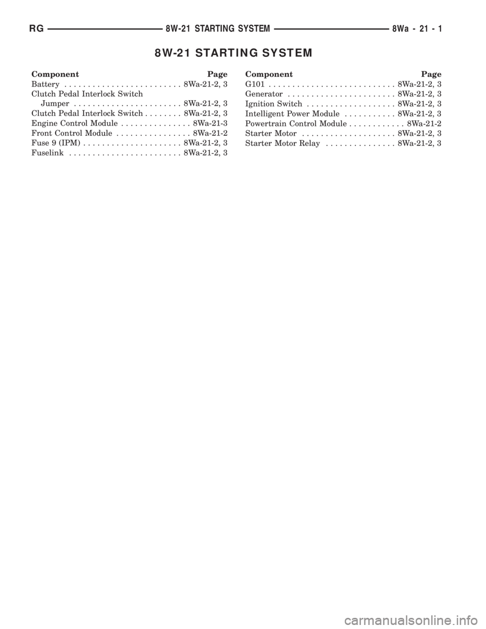
8W-21 STARTING SYSTEM
Component Page
Battery......................... 8Wa-21-2, 3
Clutch Pedal Interlock Switch
Jumper....................... 8Wa-21-2, 3
Clutch Pedal Interlock Switch........ 8Wa-21-2, 3
Engine Control Module............... 8Wa-21-3
Front Control Module................ 8Wa-21-2
Fuse 9 (IPM)..................... 8Wa-21-2, 3
Fuselink........................ 8Wa-21-2, 3Component Page
G101........................... 8Wa-21-2, 3
Generator....................... 8Wa-21-2, 3
Ignition Switch................... 8Wa-21-2, 3
Intelligent Power Module........... 8Wa-21-2, 3
Powertrain Control Module............ 8Wa-21-2
Starter Motor.................... 8Wa-21-2, 3
Starter Motor Relay............... 8Wa-21-2, 3
RG8W-21 STARTING SYSTEM8Wa-21-1
Page 3806 of 4284
When testing voltage or continuity at any control
module, use the terminal side (not the wire end) of
the connector. Do not probe a wire through the
insulation; this will damage it and eventually cause
it to fail because of corrosion.
Be careful when performing electrical tests so as
to prevent accidental shorting of terminals. Such
mistakes can damage fuses or components. Also, a
second DTC could be set, making diagnosis of the
original problem more difficult.
5.0 REQUIRED TOOLS AND
EQUIPMENT
DRBIIIt(diagnostic read-out box) scan tool
Evaporative System Diagnostic Kit #6917
fuel filler adapter #8382
fuel pressure adapter (C-6631) or #6539
fuel pressure kit (C-4799-B) or #5069
fuel release hose (C-4799-1)
Min Air flow fitting #6714
jumper wires
ohmmeter
oscilloscope
vacuum gauge
voltmeter
12 volt test light minimum 25 ohms resistance
with probe #6801
CAUTION: A 12 VOLT TEST LIGHT SHOULD
NOT BE USED FOR THE FOLLOWING
CIRCUITS, DAMAGE TO THE POWERTRAIN
CONTROLLER WILL OCCUR.
²5 Volt Supply
²8 Volt Supply
²J1850 PCI Bus
²CCD Bus
²CKP Sensor Signal
²CMP Sensor Signal
²Vehicle Speed Sensor Signal
²O2 Sensor Signal
6.0 GLOSSARY OF TERMS
ABSanti-lock brake system
backfire,
popbackfuel ignites in either the intake or
the exhaust system
CKPcrank position sensor
CMPcamshaft position sensorcuts out,
missesa steady pulsation or the inability of
the engine to maintain a consistent
rpm
DLCdata link connector (previously
called engine diagnostic connector)
detona-
tion,
spark
knocka mild to severe ping, especially un-
der loaded engine conditions
ECTengine coolant temperature sensor
EGRexhaust gas recirculation valve
genera-
torpreviously called alternator
hard
startThe engine takes longer than usual
to start, even though it is able to
crank normally.
hesita-
tion, sag,
stumbleThere is a momentary lack of re-
sponse when the throttle is opened.
This can occur at all vehicle speeds.
If it is severe enough, the engine
may stall.
IATintake air temperature sensor
IACidle air control motor
JTECCombined engine and transmission
control module
lack of
power,
sluggishThe engine has less than expected
power, with little or no increase in
vehicle speed when the throttle is
opened.
LDPleak detection pump
MAPmanifold absolute pressure sensor
MILmalfunction indicator lamp
MTVmanifold tuning valve
O2Soxygen sensor
PCIprogrammable communication inter-
face
PCMpowertrain control module
PCVpositive crankcase ventilation
PEPperipheral expansion port
poor fuel
economyThere is significantly less fuel mile-
age than other vehicles of the same
design ad configuration
12
GENERAL INFORMATION
Page 3854 of 4284
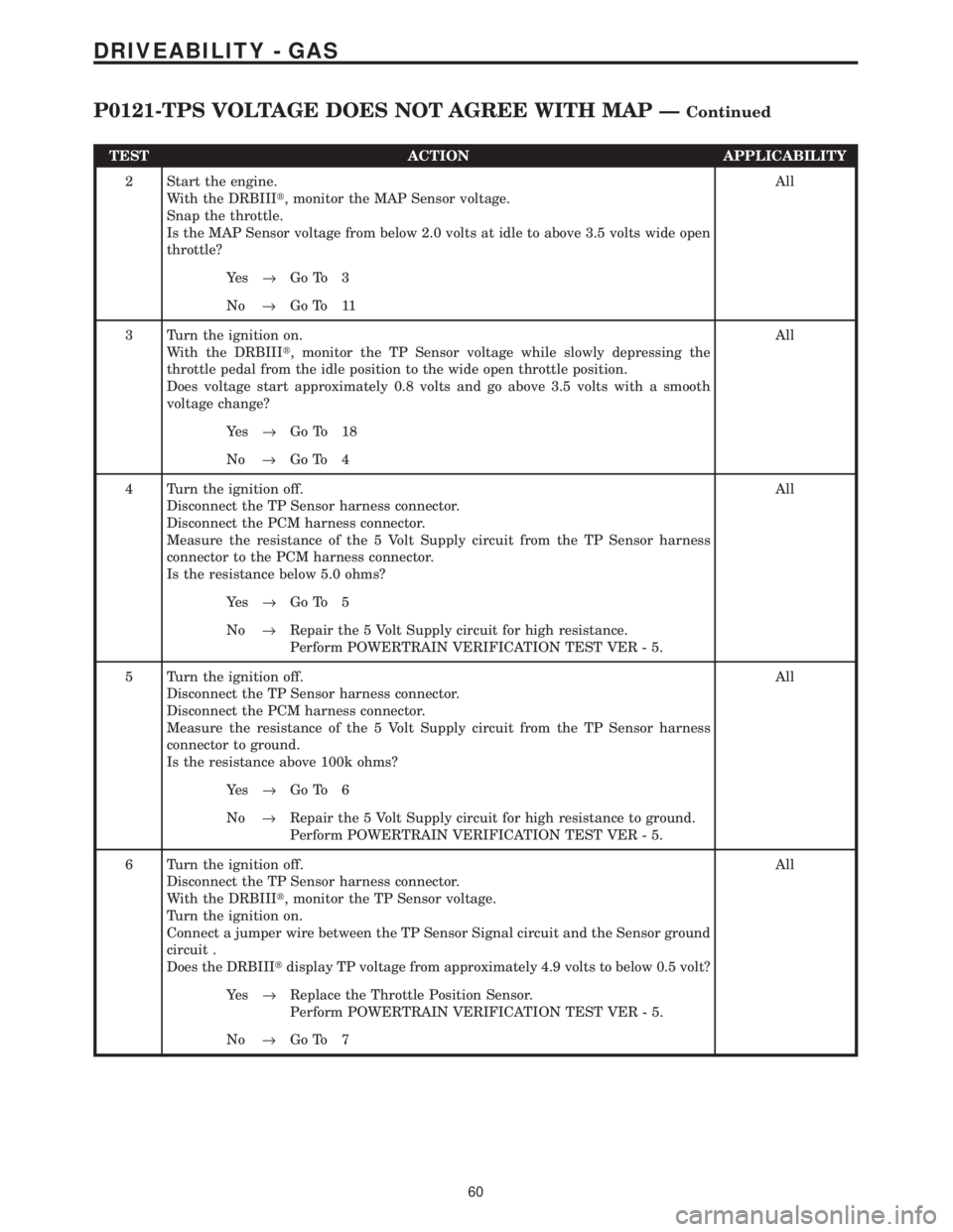
TEST ACTION APPLICABILITY
2 Start the engine.
With the DRBIIIt, monitor the MAP Sensor voltage.
Snap the throttle.
Is the MAP Sensor voltage from below 2.0 volts at idle to above 3.5 volts wide open
throttle?All
Ye s®Go To 3
No®Go To 11
3 Turn the ignition on.
With the DRBIIIt, monitor the TP Sensor voltage while slowly depressing the
throttle pedal from the idle position to the wide open throttle position.
Does voltage start approximately 0.8 volts and go above 3.5 volts with a smooth
voltage change?All
Ye s®Go To 18
No®Go To 4
4 Turn the ignition off.
Disconnect the TP Sensor harness connector.
Disconnect the PCM harness connector.
Measure the resistance of the 5 Volt Supply circuit from the TP Sensor harness
connector to the PCM harness connector.
Is the resistance below 5.0 ohms?All
Ye s®Go To 5
No®Repair the 5 Volt Supply circuit for high resistance.
Perform POWERTRAIN VERIFICATION TEST VER - 5.
5 Turn the ignition off.
Disconnect the TP Sensor harness connector.
Disconnect the PCM harness connector.
Measure the resistance of the 5 Volt Supply circuit from the TP Sensor harness
connector to ground.
Is the resistance above 100k ohms?All
Ye s®Go To 6
No®Repair the 5 Volt Supply circuit for high resistance to ground.
Perform POWERTRAIN VERIFICATION TEST VER - 5.
6 Turn the ignition off.
Disconnect the TP Sensor harness connector.
With the DRBIIIt, monitor the TP Sensor voltage.
Turn the ignition on.
Connect a jumper wire between the TP Sensor Signal circuit and the Sensor ground
circuit .
Does the DRBIIItdisplay TP voltage from approximately 4.9 volts to below 0.5 volt?All
Ye s®Replace the Throttle Position Sensor.
Perform POWERTRAIN VERIFICATION TEST VER - 5.
No®Go To 7
60
DRIVEABILITY - GAS
P0121-TPS VOLTAGE DOES NOT AGREE WITH MAP ÐContinued
Page 4053 of 4284

TEST ACTION APPLICABILITY
4 Turn ignition off.
Remove the Starter Relay from PDC.
WARNING: The Parking Brake must be on and the Transmission must be in
park for a vehicle equipped with an automatic transmission.
Warning: The engine may be cranked in the next step. Keep away from
moving engine parts.
Briefly connect a jumper wire between Starter Relay B+ circuit and the Starter Relay
Output Circuits.
Did the Starter Motor crank the engine?All
Ye s®Go To 5
No®Go To 8
5 Turn the ignition off.
Remove the Starter Relay from the PDC.
Turn the ignition on.
Using a 12-volt test light, probe the Ignition Switch Output circuit in the Starter
Relay connector.
While observing 12-volt test light, hold ignition key in the start position.
Does the test light illuminate brightly?All
Ye s®Go To 6
No®Repair the Ignition Switch Output circuit for an open or high
resistance.
Perform POWERTRAIN VERIFICATION TEST VER-1.
6 Turn the ignition off.
Remove the Starter Relay from the PDC.
Disconnect the PCM harness connector.
Measure the Starter Relay Control circuit between the Relay terminal and the PCM
harness connector.
Is the resistance below 5.0 ohms?All
Ye s®Go To 7
No®Repair the Starter Relay Control circuit for an open.
Perform POWERTRAIN VERIFICATION TEST VER-1.
7 Turn the ignition off.
Install a substitute a Relay in the of the Starter Motor Relay.
Attempt to start the vehicle.
Does the engine crank over?All
Ye s®Replace the Starter Motor Relay.
Perform POWERTRAIN VERIFICATION TEST VER-1.
No®Replace and program the Powertrain Control Module in accor-
dance with the Service Information.
Perform POWERTRAIN VERIFICATION TEST VER-1.
259
STARTING
*NO CRANK CONDITION ÐContinued
Page 4070 of 4284
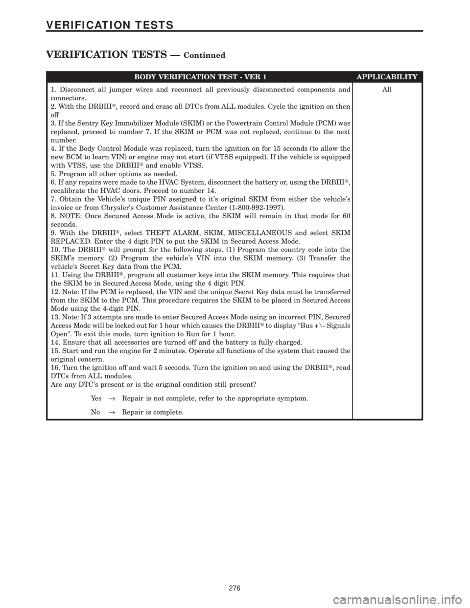
BODY VERIFICATION TEST - VER 1 APPLICABILITY
1. Disconnect all jumper wires and reconnect all previously disconnected components and
connectors.
2. With the DRBIIIt, record and erase all DTCs from ALL modules. Cycle the ignition on then
off
3. If the Sentry Key Immobilizer Module (SKIM) or the Powertrain Control Module (PCM) was
replaced, proceed to number 7. If the SKIM or PCM was not replaced, continue to the next
number.
4. If the Body Control Module was replaced, turn the ignition on for 15 seconds (to allow the
new BCM to learn VIN) or engine may not start (if VTSS equipped). If the vehicle is equipped
with VTSS, use the DRBIIItand enable VTSS.
5. Program all other options as needed.
6. If any repairs were made to the HVAC System, disconnect the battery or, using the DRBIIIt,
recalibrate the HVAC doors. Proceed to number 14.
7. Obtain the Vehicle's unique PIN assigned to it's original SKIM from either the vehicle's
invoice or from Chrysler's Customer Assistance Center (1-800-992-1997).
8. NOTE: Once Secured Access Mode is active, the SKIM will remain in that mode for 60
seconds.
9. With the DRBIIIt, select THEFT ALARM, SKIM, MISCELLANEOUS and select SKIM
REPLACED. Enter the 4 digit PIN to put the SKIM in Secured Access Mode.
10. The DRBIIItwill prompt for the following steps. (1) Program the country code into the
SKIM's memory. (2) Program the vehicle's VIN into the SKIM memory. (3) Transfer the
vehicle's Secret Key data from the PCM.
11. Using the DRBIIIt, program all customer keys into the SKIM memory. This requires that
the SKIM be in Secured Access Mode, using the 4 digit PIN.
12. Note: If the PCM is replaced, the VIN and the unique Secret Key data must be transferred
from the SKIM to the PCM. This procedure requires the SKIM to be placed in Secured Access
Mode using the 4-digit PIN.
13. Note: If 3 attempts are made to enter Secured Access Mode using an incorrect PIN, Secured
Access Mode will be locked out for 1 hour which causes the DRBIIItto display9Bus +\- Signals
Open9. To exit this mode, turn ignition to Run for 1 hour.
14. Ensure that all accessories are turned off and the battery is fully charged.
15. Start and run the engine for 2 minutes. Operate all functions of the system that caused the
original concern.
16. Turn the ignition off and wait 5 seconds. Turn the ignition on and using the DRBIIIt, read
DTCs from ALL modules.
Are any DTC's present or is the original condition still present?All
Ye s®Repair is not complete, refer to the appropriate symptom.
No®Repair is complete.
276
VERIFICATION TESTS
VERIFICATION TESTS ÐContinued
Page 4125 of 4284
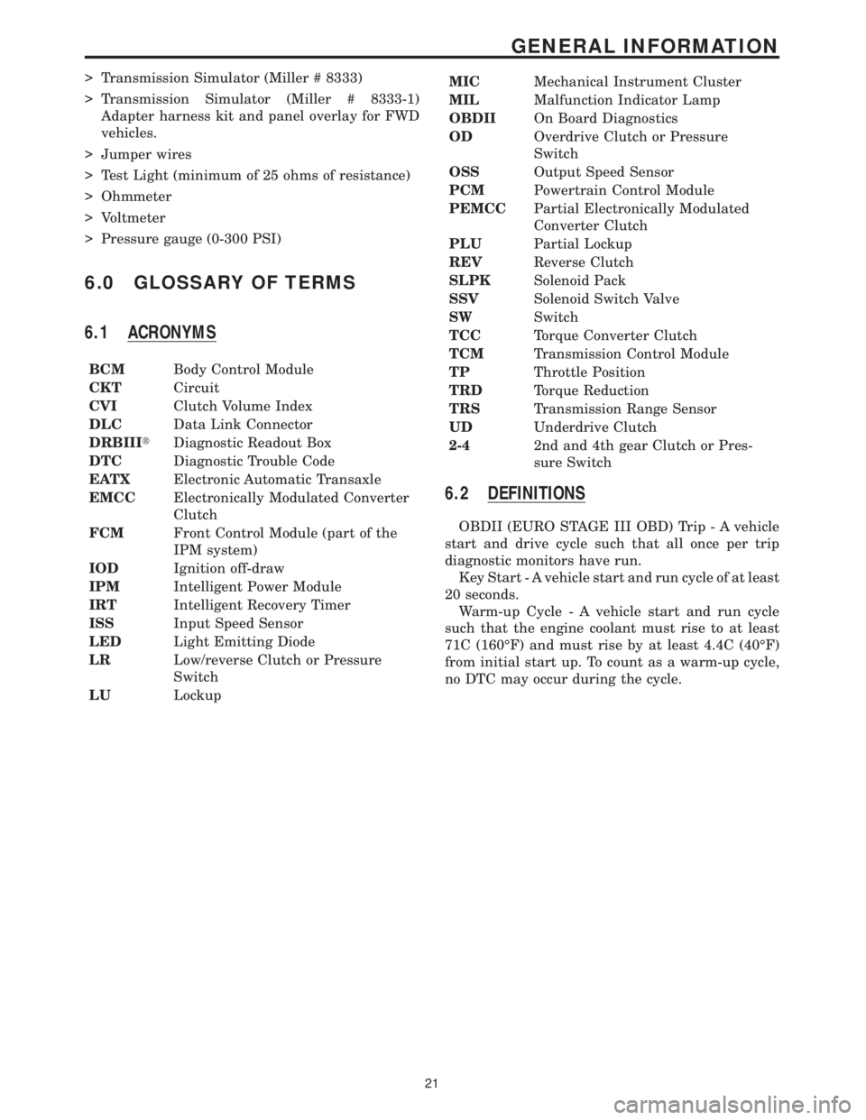
> Transmission Simulator (Miller # 8333)
> Transmission Simulator (Miller # 8333-1)
Adapter harness kit and panel overlay for FWD
vehicles.
> Jumper wires
> Test Light (minimum of 25 ohms of resistance)
> Ohmmeter
> Voltmeter
> Pressure gauge (0-300 PSI)
6.0 GLOSSARY OF TERMS
6.1 ACRONYMS
BCMBody Control Module
CKTCircuit
CVIClutch Volume Index
DLCData Link Connector
DRBIIItDiagnostic Readout Box
DTCDiagnostic Trouble Code
EATXElectronic Automatic Transaxle
EMCCElectronically Modulated Converter
Clutch
FCMFront Control Module (part of the
IPM system)
IODIgnition off-draw
IPMIntelligent Power Module
IRTIntelligent Recovery Timer
ISSInput Speed Sensor
LEDLight Emitting Diode
LRLow/reverse Clutch or Pressure
Switch
LULockupMICMechanical Instrument Cluster
MILMalfunction Indicator Lamp
OBDIIOn Board Diagnostics
ODOverdrive Clutch or Pressure
Switch
OSSOutput Speed Sensor
PCMPowertrain Control Module
PEMCCPartial Electronically Modulated
Converter Clutch
PLUPartial Lockup
REVReverse Clutch
SLPKSolenoid Pack
SSVSolenoid Switch Valve
SWSwitch
TCCTorque Converter Clutch
TCMTransmission Control Module
TPThrottle Position
TRDTorque Reduction
TRSTransmission Range Sensor
UDUnderdrive Clutch
2-42nd and 4th gear Clutch or Pres-
sure Switch
6.2 DEFINITIONS
OBDII (EURO STAGE III OBD) Trip - A vehicle
start and drive cycle such that all once per trip
diagnostic monitors have run.
Key Start - A vehicle start and run cycle of at least
20 seconds.
Warm-up Cycle - A vehicle start and run cycle
such that the engine coolant must rise to at least
71C (160ÉF) and must rise by at least 4.4C (40ÉF)
from initial start up. To count as a warm-up cycle,
no DTC may occur during the cycle.
21
GENERAL INFORMATION