2001 CHRYSLER VOYAGER relay
[x] Cancel search: relayPage 1394 of 4284
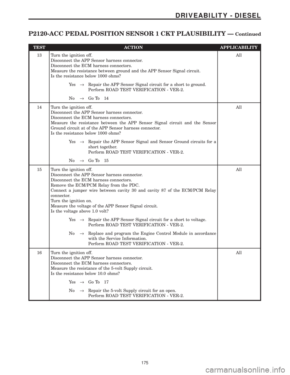
TEST ACTION APPLICABILITY
13 Turn the ignition off.
Disconnect the APP Sensor harness connector.
Disconnect the ECM harness connectors.
Measure the resistance between ground and the APP Sensor Signal circuit.
Is the resistance below 1000 ohms?All
Ye s®Repair the APP Sensor Signal circuit for a short to ground.
Perform ROAD TEST VERIFICATION - VER-2.
No®Go To 14
14 Turn the ignition off.
Disconnect the APP Sensor harness connector.
Disconnect the ECM harness connectors.
Measure the resistance between the APP Sensor Signal circuit and the Sensor
Ground circuit at of the APP Sensor harness connector.
Is the resistance below 1000 ohms?All
Ye s®Repair the APP Sensor Signal and Sensor Ground circuits for a
short together.
Perform ROAD TEST VERIFICATION - VER-2.
No®Go To 15
15 Turn the ignition off.
Disconnect the APP Sensor harness connector.
Disconnect the ECM harness connectors.
Remove the ECM/PCM Relay from the PDC.
Connect a jumper wire between cavity 30 and cavity 87 of the ECM/PCM Relay
connector.
Turn the ignition on.
Measure the voltage of the APP Sensor Signal circuit.
Is the voltage above 1.0 volt?All
Ye s®Repair the APP Sensor Signal circuit for a short to voltage.
Perform ROAD TEST VERIFICATION - VER-2.
No®Replace and program the Engine Control Module in accordance
with the Service Information.
Perform ROAD TEST VERIFICATION - VER-2.
16 Turn the ignition off.
Disconnect the APP Sensor harness connector.
Disconnect the ECM harness connectors.
Measure the resistance of the 5-volt Supply circuit.
Is the resistance below 10.0 ohms?All
Ye s®Go To 17
No®Repair the 5-volt Supply circuit for an open.
Perform ROAD TEST VERIFICATION - VER-2.
175
DRIVEABILITY - DIESEL
P2120-ACC PEDAL POSITION SENSOR 1 CKT PLAUSIBILITY ÐContinued
Page 1395 of 4284
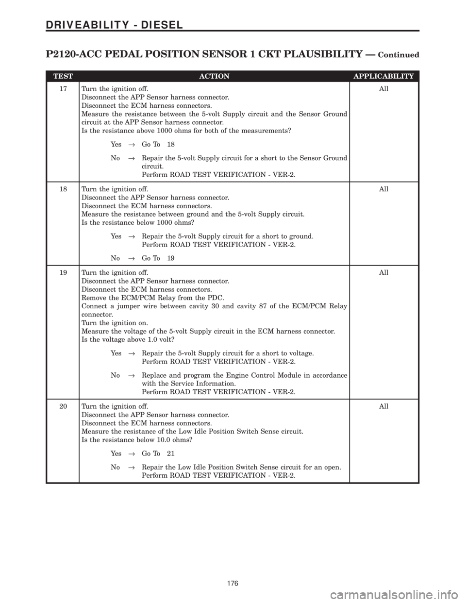
TEST ACTION APPLICABILITY
17 Turn the ignition off.
Disconnect the APP Sensor harness connector.
Disconnect the ECM harness connectors.
Measure the resistance between the 5-volt Supply circuit and the Sensor Ground
circuit at the APP Sensor harness connector.
Is the resistance above 1000 ohms for both of the measurements?All
Ye s®Go To 18
No®Repair the 5-volt Supply circuit for a short to the Sensor Ground
circuit.
Perform ROAD TEST VERIFICATION - VER-2.
18 Turn the ignition off.
Disconnect the APP Sensor harness connector.
Disconnect the ECM harness connectors.
Measure the resistance between ground and the 5-volt Supply circuit.
Is the resistance below 1000 ohms?All
Ye s®Repair the 5-volt Supply circuit for a short to ground.
Perform ROAD TEST VERIFICATION - VER-2.
No®Go To 19
19 Turn the ignition off.
Disconnect the APP Sensor harness connector.
Disconnect the ECM harness connectors.
Remove the ECM/PCM Relay from the PDC.
Connect a jumper wire between cavity 30 and cavity 87 of the ECM/PCM Relay
connector.
Turn the ignition on.
Measure the voltage of the 5-volt Supply circuit in the ECM harness connector.
Is the voltage above 1.0 volt?All
Ye s®Repair the 5-volt Supply circuit for a short to voltage.
Perform ROAD TEST VERIFICATION - VER-2.
No®Replace and program the Engine Control Module in accordance
with the Service Information.
Perform ROAD TEST VERIFICATION - VER-2.
20 Turn the ignition off.
Disconnect the APP Sensor harness connector.
Disconnect the ECM harness connectors.
Measure the resistance of the Low Idle Position Switch Sense circuit.
Is the resistance below 10.0 ohms?All
Ye s®Go To 21
No®Repair the Low Idle Position Switch Sense circuit for an open.
Perform ROAD TEST VERIFICATION - VER-2.
176
DRIVEABILITY - DIESEL
P2120-ACC PEDAL POSITION SENSOR 1 CKT PLAUSIBILITY ÐContinued
Page 1396 of 4284
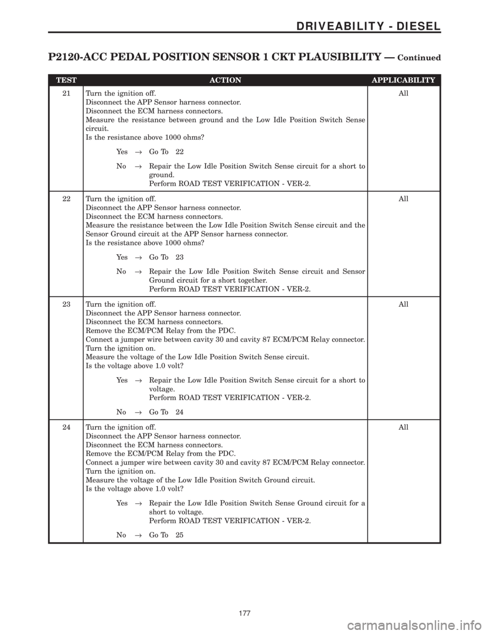
TEST ACTION APPLICABILITY
21 Turn the ignition off.
Disconnect the APP Sensor harness connector.
Disconnect the ECM harness connectors.
Measure the resistance between ground and the Low Idle Position Switch Sense
circuit.
Is the resistance above 1000 ohms?All
Ye s®Go To 22
No®Repair the Low Idle Position Switch Sense circuit for a short to
ground.
Perform ROAD TEST VERIFICATION - VER-2.
22 Turn the ignition off.
Disconnect the APP Sensor harness connector.
Disconnect the ECM harness connectors.
Measure the resistance between the Low Idle Position Switch Sense circuit and the
Sensor Ground circuit at the APP Sensor harness connector.
Is the resistance above 1000 ohms?All
Ye s®Go To 23
No®Repair the Low Idle Position Switch Sense circuit and Sensor
Ground circuit for a short together.
Perform ROAD TEST VERIFICATION - VER-2.
23 Turn the ignition off.
Disconnect the APP Sensor harness connector.
Disconnect the ECM harness connectors.
Remove the ECM/PCM Relay from the PDC.
Connect a jumper wire between cavity 30 and cavity 87 ECM/PCM Relay connector.
Turn the ignition on.
Measure the voltage of the Low Idle Position Switch Sense circuit.
Is the voltage above 1.0 volt?All
Ye s®Repair the Low Idle Position Switch Sense circuit for a short to
voltage.
Perform ROAD TEST VERIFICATION - VER-2.
No®Go To 24
24 Turn the ignition off.
Disconnect the APP Sensor harness connector.
Disconnect the ECM harness connectors.
Remove the ECM/PCM Relay from the PDC.
Connect a jumper wire between cavity 30 and cavity 87 ECM/PCM Relay connector.
Turn the ignition on.
Measure the voltage of the Low Idle Position Switch Ground circuit.
Is the voltage above 1.0 volt?All
Ye s®Repair the Low Idle Position Switch Sense Ground circuit for a
short to voltage.
Perform ROAD TEST VERIFICATION - VER-2.
No®Go To 25
177
DRIVEABILITY - DIESEL
P2120-ACC PEDAL POSITION SENSOR 1 CKT PLAUSIBILITY ÐContinued
Page 1398 of 4284
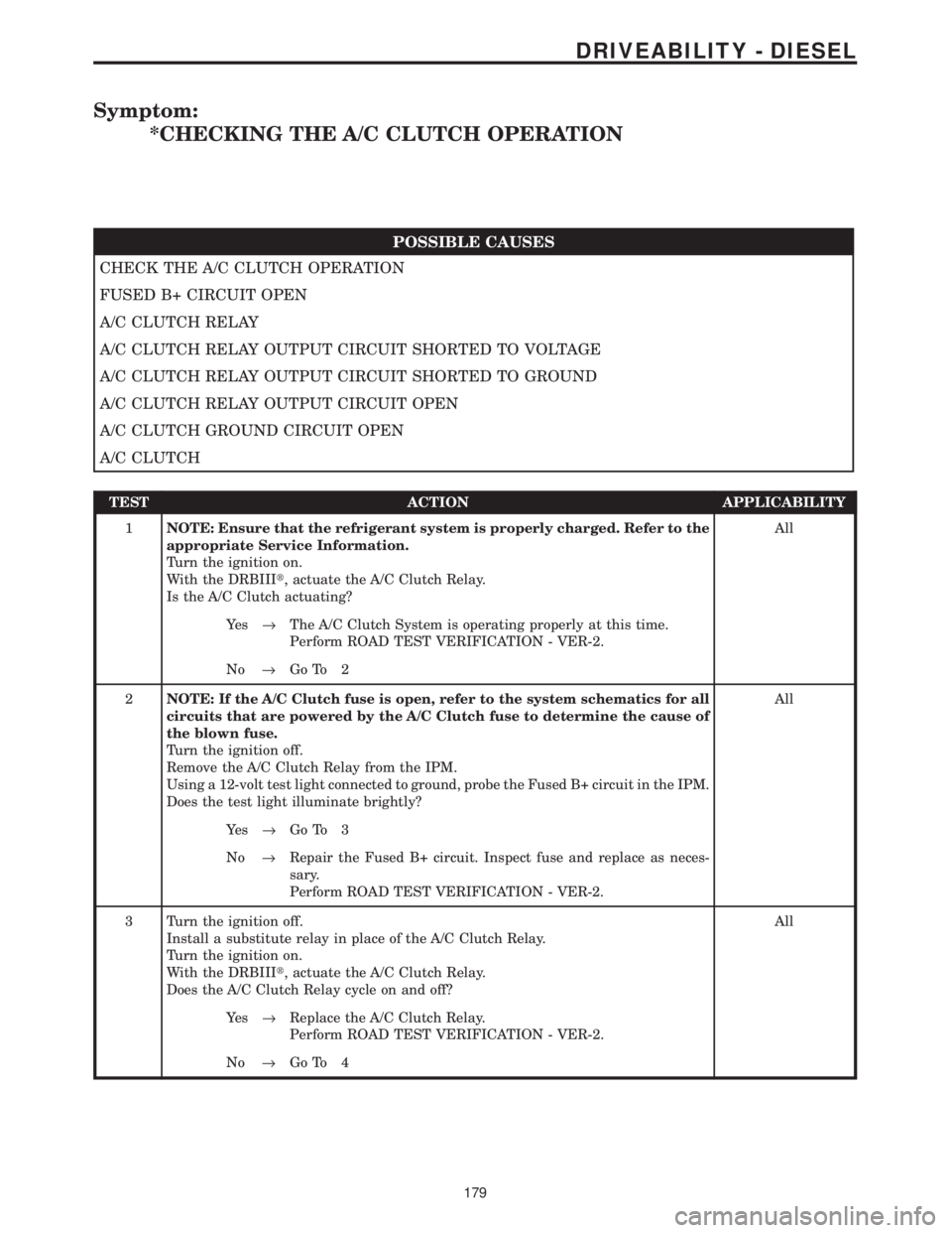
Symptom:
*CHECKING THE A/C CLUTCH OPERATION
POSSIBLE CAUSES
CHECK THE A/C CLUTCH OPERATION
FUSED B+ CIRCUIT OPEN
A/C CLUTCH RELAY
A/C CLUTCH RELAY OUTPUT CIRCUIT SHORTED TO VOLTAGE
A/C CLUTCH RELAY OUTPUT CIRCUIT SHORTED TO GROUND
A/C CLUTCH RELAY OUTPUT CIRCUIT OPEN
A/C CLUTCH GROUND CIRCUIT OPEN
A/C CLUTCH
TEST ACTION APPLICABILITY
1NOTE: Ensure that the refrigerant system is properly charged. Refer to the
appropriate Service Information.
Turn the ignition on.
With the DRBIIIt, actuate the A/C Clutch Relay.
Is the A/C Clutch actuating?All
Ye s®The A/C Clutch System is operating properly at this time.
Perform ROAD TEST VERIFICATION - VER-2.
No®Go To 2
2NOTE: If the A/C Clutch fuse is open, refer to the system schematics for all
circuits that are powered by the A/C Clutch fuse to determine the cause of
the blown fuse.
Turn the ignition off.
Remove the A/C Clutch Relay from the IPM.
Using a 12-volt test light connected to ground, probe the Fused B+ circuit in the IPM.
Does the test light illuminate brightly?All
Ye s®Go To 3
No®Repair the Fused B+ circuit. Inspect fuse and replace as neces-
sary.
Perform ROAD TEST VERIFICATION - VER-2.
3 Turn the ignition off.
Install a substitute relay in place of the A/C Clutch Relay.
Turn the ignition on.
With the DRBIIIt, actuate the A/C Clutch Relay.
Does the A/C Clutch Relay cycle on and off?All
Ye s®Replace the A/C Clutch Relay.
Perform ROAD TEST VERIFICATION - VER-2.
No®Go To 4
179
DRIVEABILITY - DIESEL
Page 1399 of 4284
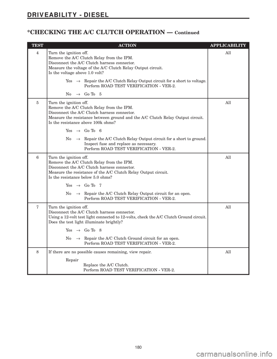
TEST ACTION APPLICABILITY
4 Turn the ignition off.
Remove the A/C Clutch Relay from the IPM.
Disconnect the A/C Clutch harness connector.
Measure the voltage of the A/C Clutch Relay Output circuit.
Is the voltage above 1.0 volt?All
Ye s®Repair the A/C Clutch Relay Output circuit for a short to voltage.
Perform ROAD TEST VERIFICATION - VER-2.
No®Go To 5
5 Turn the ignition off.
Remove the A/C Clutch Relay from the IPM.
Disconnect the A/C Clutch harness connector.
Measure the resistance between ground and the A/C Clutch Relay Output circuit.
Is the resistance above 100k ohms?All
Ye s®Go To 6
No®Repair the A/C Clutch Relay Output circuit for a short to ground.
Inspect fuse and replace as necessary.
Perform ROAD TEST VERIFICATION - VER-2.
6 Turn the ignition off.
Remove the A/C Clutch Relay from the IPM.
Disconnect the A/C Clutch harness connector.
Measure the resistance of the A/C Clutch Relay Output circuit.
Is the resistance below 5.0 ohms?All
Ye s®Go To 7
No®Repair the A/C Clutch Relay Output circuit for an open.
Perform ROAD TEST VERIFICATION - VER-2.
7 Turn the ignition off.
Disconnect the A/C Clutch harness connector.
Using a 12-volt test light connected to 12-volts, check the A/C Clutch Ground circuit.
Does the test light illuminate brightly?All
Ye s®Go To 8
No®Repair the A/C Clutch Ground circuit for an open.
Perform ROAD TEST VERIFICATION - VER-2.
8 If there are no possible causes remaining, view repair. All
Repair
Replace the A/C Clutch.
Perform ROAD TEST VERIFICATION - VER-2.
180
DRIVEABILITY - DIESEL
*CHECKING THE A/C CLUTCH OPERATION ÐContinued
Page 1402 of 4284
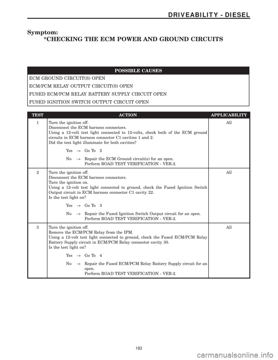
Symptom:
*CHECKING THE ECM POWER AND GROUND CIRCUITS
POSSIBLE CAUSES
ECM GROUND CIRCUIT(S) OPEN
ECM/PCM RELAY OUTPUT CIRCUIT(S) OPEN
FUSED ECM/PCM RELAY BATTERY SUPPLY CIRCUIT OPEN
FUSED IGNITION SWITCH OUTPUT CIRCUIT OPEN
TEST ACTION APPLICABILITY
1 Turn the ignition off.
Disconnect the ECM harness connectors.
Using a 12-volt test light connected to 12-volts, check both of the ECM ground
circuits in ECM harness connector C1 cavities 1 and 2.
Did the test light illuminate for both cavities?All
Ye s®Go To 2
No®Repair the ECM Ground circuit(s) for an open.
Perform ROAD TEST VERIFICATION - VER-2.
2 Turn the ignition off.
Disconnect the ECM harness connectors.
Turn the ignition on.
Using a 12-volt test light connected to ground, check the Fused Ignition Switch
Output circuit in ECM harness connector C1 cavity 22.
Is the test light on?All
Ye s®Go To 3
No®Repair the Fused Ignition Switch Output circuit for an open.
Perform ROAD TEST VERIFICATION - VER-2.
3 Turn the ignition off.
Remove the ECM/PCM Relay from the IPM.
Using a 12-volt test light connected to ground, check the Fused ECM/PCM Relay
Battery Supply circuit in ECM/PCM Relay connector cavity 30.
Is the test light on?All
Ye s®Go To 4
No®Repair the Fused ECM/PCM Relay Battery Supply circuit for an
open.
Perform ROAD TEST VERIFICATION - VER-2.
183
DRIVEABILITY - DIESEL
Page 1403 of 4284
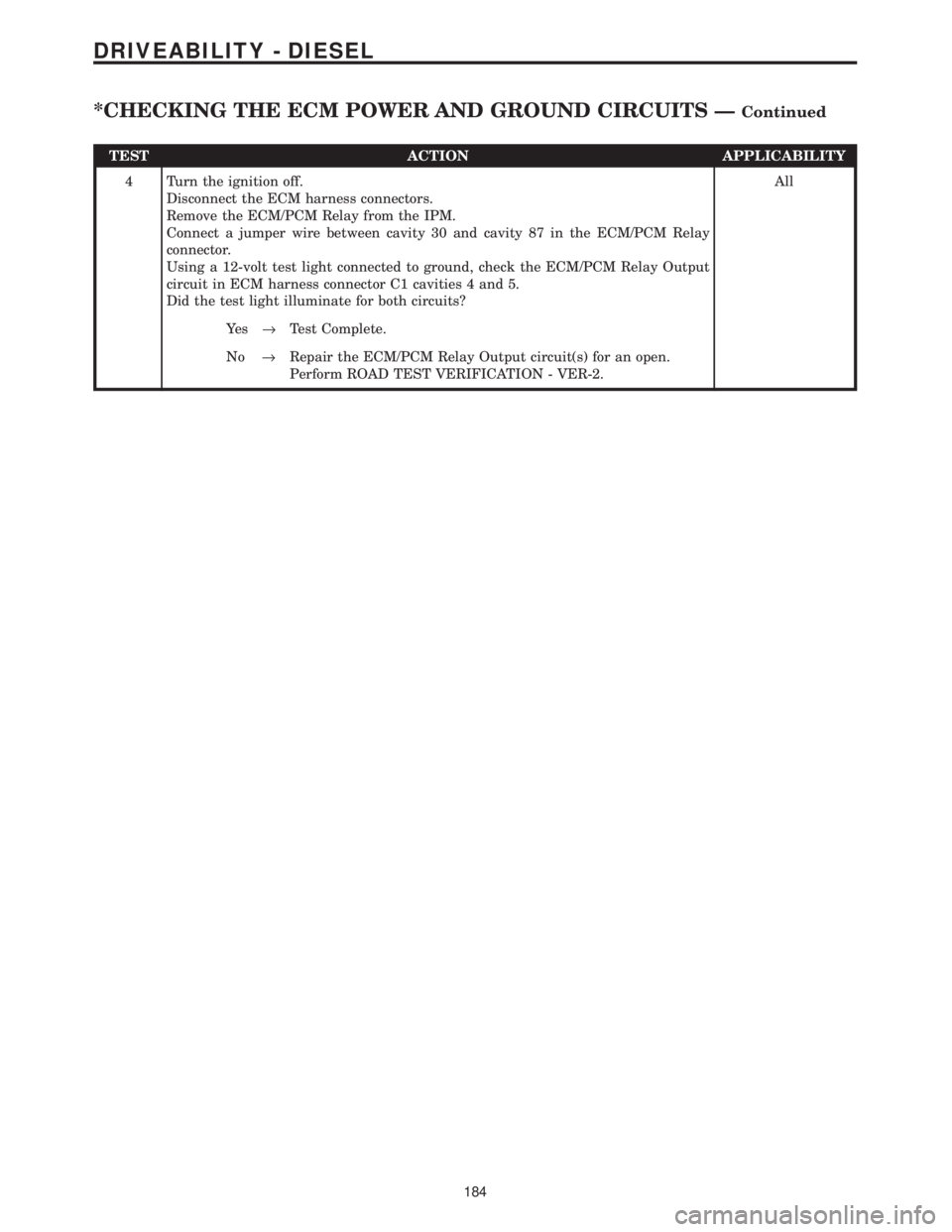
TEST ACTION APPLICABILITY
4 Turn the ignition off.
Disconnect the ECM harness connectors.
Remove the ECM/PCM Relay from the IPM.
Connect a jumper wire between cavity 30 and cavity 87 in the ECM/PCM Relay
connector.
Using a 12-volt test light connected to ground, check the ECM/PCM Relay Output
circuit in ECM harness connector C1 cavities 4 and 5.
Did the test light illuminate for both circuits?All
Ye s®Test Complete.
No®Repair the ECM/PCM Relay Output circuit(s) for an open.
Perform ROAD TEST VERIFICATION - VER-2.
184
DRIVEABILITY - DIESEL
*CHECKING THE ECM POWER AND GROUND CIRCUITS ÐContinued
Page 1404 of 4284

Symptom:
*CHECKING THE EGR SYSTEM
POSSIBLE CAUSES
ECM/PCM RELAY OUTPUT CIRCUIT OPEN
EGR SOLENOID CONTROL CIRCUIT OPEN
EGR VALVE
VACUUM SUPPLY HOSE
TEST ACTION APPLICABILITY
1 Disconnect the Vacuum Supply Hose at the EGR solenoid.
Connect a vacuum gauge to the Vacuum Supply Hose.
Start the engine and allow the engine to idle.
Is the vacuum above 10 inches of mercury at idle?All
Ye s®Go To 2
No®Repair leaking or restricted Vacuum Supply Hose or faulty
Vacuum Supply Pump.
Perform ROAD TEST VERIFICATION - VER-2.
2 Turn the ignition off.
Disconnect the EGR Solenoid harness connector.
Turn the ignition on.
Using a 12-volt test light connected to ground, check the ECM/PCM Relay Output
circuit at the EGR Solenoid harness connector.
Is the test light on?All
Ye s®Go To 3
No®Repair the ECM/PCM Relay Output circuit for an open.
Perform ROAD TEST VERIFICATION - VER-2.
3 Turn the ignition off.
Disconnect the EGR Solenoid harness connector.
Disconnect the ECM harness connectors.
Measure the resistance of the EGR Solenoid Control circuit.
Is the resistance below 10.0 ohms?All
Ye s®Go To 4
No®Repair the EGR Solenoid Control circuit for an open.
Perform ROAD TEST VERIFICATION - VER-2.
4NOTE: The Vacuum Output Hose must not be leaking or restricted for the
result of this test to be valid.
Turn the ignition off.
Disconnect the Vacuum Supply and Vacuum Output Hoses in the EGR Solenoid
vacuum connector.
Connect the Vacuum Supply Hose to the Vacuum Output Hose.
Test drive the vehicle and observe vehicle performance.
Is there a power reduction on vehicle acceleration?All
Ye s®Test Complete.
No®Replace the EGR Valve.
Perform ROAD TEST VERIFICATION - VER-2.
185
DRIVEABILITY - DIESEL