2001 CHRYSLER VOYAGER engine
[x] Cancel search: enginePage 1183 of 4284
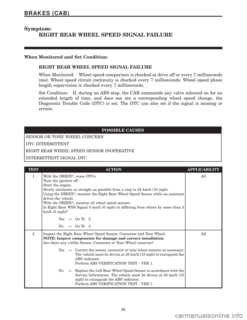
Symptom:
RIGHT REAR WHEEL SPEED SIGNAL FAILURE
When Monitored and Set Condition:
RIGHT REAR WHEEL SPEED SIGNAL FAILURE
When Monitored: Wheel speed comparison is checked at drive off or every 7 milliseconds
(ms). Wheel speed circuit continuity is checked every 7 milliseconds. Wheel speed phase
length supervision is checked every 7 milliseconds.
Set Condition: If, during an ABS stop, the CAB commands any valve solenoid on for an
extended length of time, and does not see a corresponding wheel speed change, the
Diagnostic Trouble Code (DTC) is set. The DTC can also set if the signal is missing or
erratic.
POSSIBLE CAUSES
SENSOR OR TONE WHEEL CONCERN
DTC INTERMITTENT
RIGHT REAR WHEEL SPEED SENSOR INOPERATIVE
INTERMITTENT SIGNAL DTC
TEST ACTION APPLICABILITY
1 With the DRBIIIt, erase DTCs.
Turn the ignition off.
Start the engine.
Slowly accelerate as straight as possible from a stop to 24 km/h (15 mph).
Using the DRBIIIt, monitor the Right Rear Wheel Speed Sensor while an assistant
drives the vehicle.
With the DRBIIIt, monitor all wheel speed sensors.
Is Right Rear WSS Signal 0 km/h (0 mph) or differing from others by more than 5
km/h (3 mph)?All
Ye s®Go To 2
No®Go To 3
2 Inspect the Right Rear Wheel Speed Sensor, Connector and Tone Wheel.
NOTE: Inspect components for damage and correct installation.
Are there any visible Sensor, Connector or Tone Wheel concerns?All
Ye s®Correct the sensor, connector or tone wheel concern as necessary.
The vehicle must be driven at 25 km/h (15 mph) to extinguish the
ABS indicator.
Perform ABS VERIFICATION TEST - VER 1.
No®Replace the Left Rear Wheel Speed Sensor in accordance with the
Service Information. The vehicle must be driven at 25 km/h (15
mph) to extinguish the ABS indicator.
Perform ABS VERIFICATION TEST - VER 1.
26
BRAKES (CAB)
Page 1185 of 4284
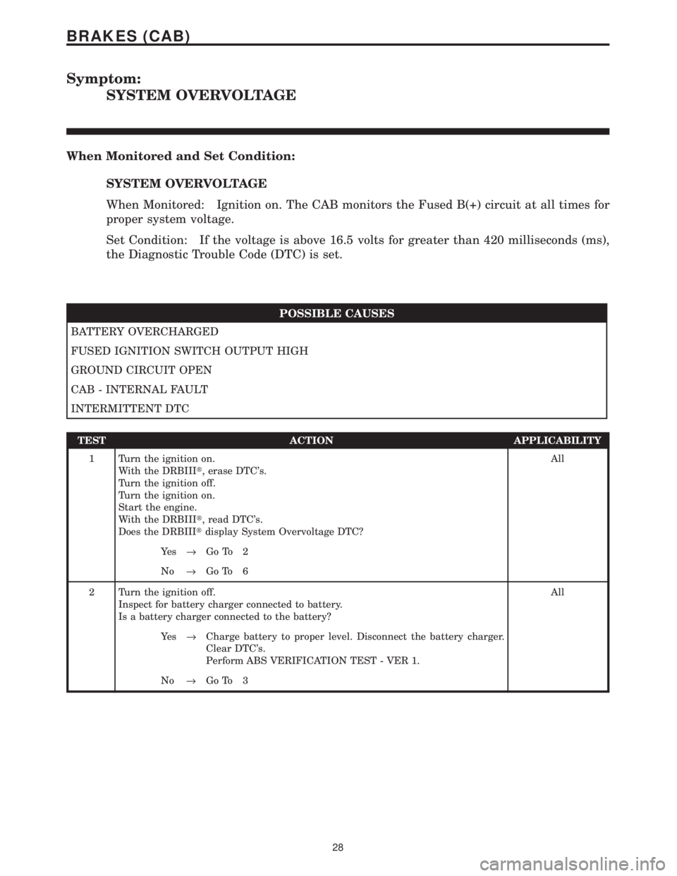
Symptom:
SYSTEM OVERVOLTAGE
When Monitored and Set Condition:
SYSTEM OVERVOLTAGE
When Monitored: Ignition on. The CAB monitors the Fused B(+) circuit at all times for
proper system voltage.
Set Condition: If the voltage is above 16.5 volts for greater than 420 milliseconds (ms),
the Diagnostic Trouble Code (DTC) is set.
POSSIBLE CAUSES
BATTERY OVERCHARGED
FUSED IGNITION SWITCH OUTPUT HIGH
GROUND CIRCUIT OPEN
CAB - INTERNAL FAULT
INTERMITTENT DTC
TEST ACTION APPLICABILITY
1 Turn the ignition on.
With the DRBIIIt, erase DTC's.
Turn the ignition off.
Turn the ignition on.
Start the engine.
With the DRBIIIt, read DTC's.
Does the DRBIIItdisplay System Overvoltage DTC?All
Ye s®Go To 2
No®Go To 6
2 Turn the ignition off.
Inspect for battery charger connected to battery.
Is a battery charger connected to the battery?All
Ye s®Charge battery to proper level. Disconnect the battery charger.
Clear DTC's.
Perform ABS VERIFICATION TEST - VER 1.
No®Go To 3
28
BRAKES (CAB)
Page 1186 of 4284
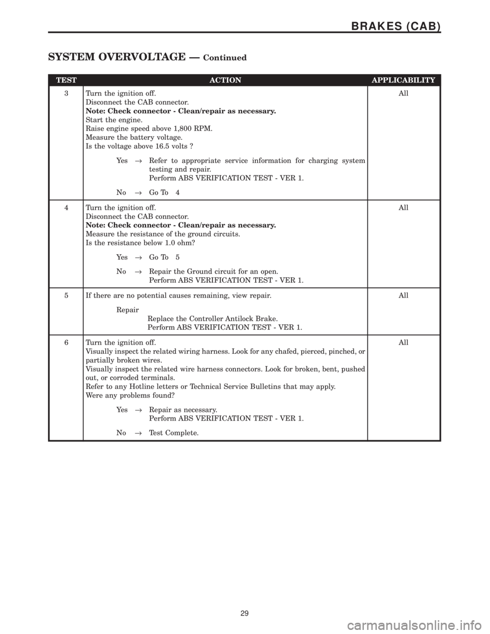
TEST ACTION APPLICABILITY
3 Turn the ignition off.
Disconnect the CAB connector.
Note: Check connector - Clean/repair as necessary.
Start the engine.
Raise engine speed above 1,800 RPM.
Measure the battery voltage.
Is the voltage above 16.5 volts ?All
Ye s®Refer to appropriate service information for charging system
testing and repair.
Perform ABS VERIFICATION TEST - VER 1.
No®Go To 4
4 Turn the ignition off.
Disconnect the CAB connector.
Note: Check connector - Clean/repair as necessary.
Measure the resistance of the ground circuits.
Is the resistance below 1.0 ohm?All
Ye s®Go To 5
No®Repair the Ground circuit for an open.
Perform ABS VERIFICATION TEST - VER 1.
5 If there are no potential causes remaining, view repair. All
Repair
Replace the Controller Antilock Brake.
Perform ABS VERIFICATION TEST - VER 1.
6 Turn the ignition off.
Visually inspect the related wiring harness. Look for any chafed, pierced, pinched, or
partially broken wires.
Visually inspect the related wire harness connectors. Look for broken, bent, pushed
out, or corroded terminals.
Refer to any Hotline letters or Technical Service Bulletins that may apply.
Were any problems found?All
Ye s®Repair as necessary.
Perform ABS VERIFICATION TEST - VER 1.
No®Test Complete.
29
BRAKES (CAB)
SYSTEM OVERVOLTAGE ÐContinued
Page 1187 of 4284
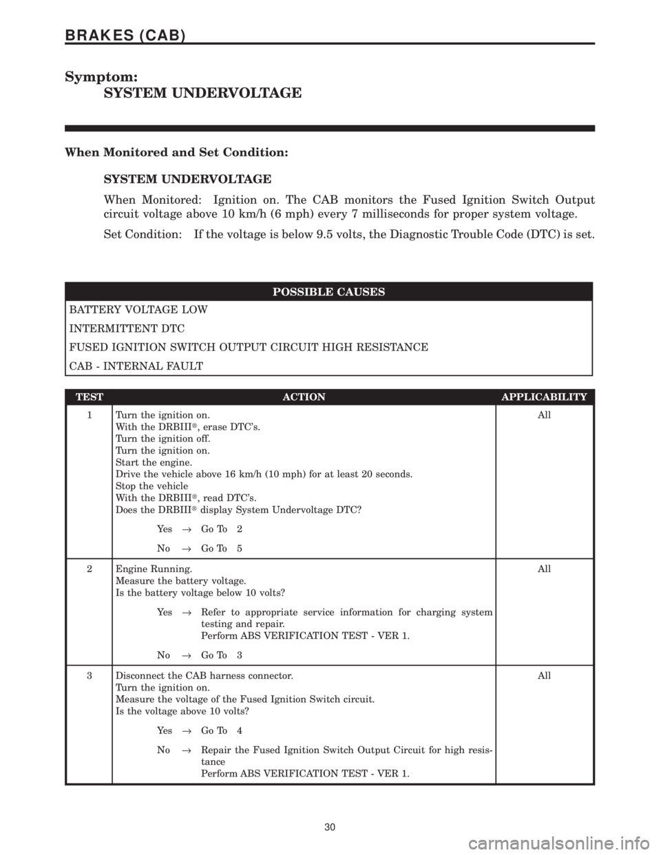
Symptom:
SYSTEM UNDERVOLTAGE
When Monitored and Set Condition:
SYSTEM UNDERVOLTAGE
When Monitored: Ignition on. The CAB monitors the Fused Ignition Switch Output
circuit voltage above 10 km/h (6 mph) every 7 milliseconds for proper system voltage.
Set Condition: If the voltage is below 9.5 volts, the Diagnostic Trouble Code (DTC) is set.
POSSIBLE CAUSES
BATTERY VOLTAGE LOW
INTERMITTENT DTC
FUSED IGNITION SWITCH OUTPUT CIRCUIT HIGH RESISTANCE
CAB - INTERNAL FAULT
TEST ACTION APPLICABILITY
1 Turn the ignition on.
With the DRBIIIt, erase DTC's.
Turn the ignition off.
Turn the ignition on.
Start the engine.
Drive the vehicle above 16 km/h (10 mph) for at least 20 seconds.
Stop the vehicle
With the DRBIIIt, read DTC's.
Does the DRBIIItdisplay System Undervoltage DTC?All
Ye s®Go To 2
No®Go To 5
2 Engine Running.
Measure the battery voltage.
Is the battery voltage below 10 volts?All
Ye s®Refer to appropriate service information for charging system
testing and repair.
Perform ABS VERIFICATION TEST - VER 1.
No®Go To 3
3 Disconnect the CAB harness connector.
Turn the ignition on.
Measure the voltage of the Fused Ignition Switch circuit.
Is the voltage above 10 volts?All
Ye s®Go To 4
No®Repair the Fused Ignition Switch Output Circuit for high resis-
tance
Perform ABS VERIFICATION TEST - VER 1.
30
BRAKES (CAB)
Page 1197 of 4284
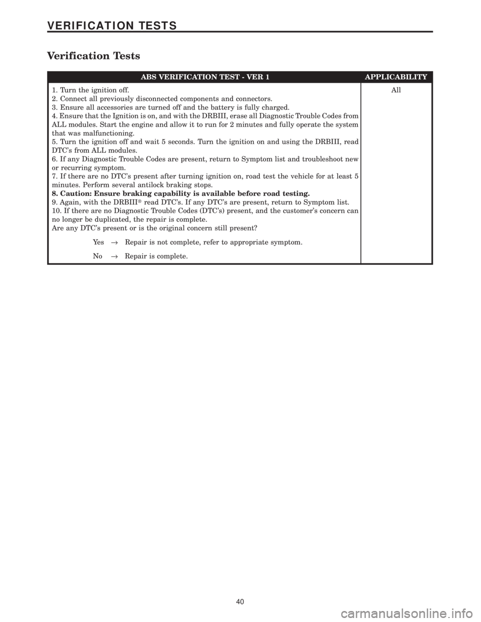
Verification Tests
ABS VERIFICATION TEST - VER 1 APPLICABILITY
1. Turn the ignition off.
2. Connect all previously disconnected components and connectors.
3. Ensure all accessories are turned off and the battery is fully charged.
4. Ensure that the Ignition is on, and with the DRBIII, erase all Diagnostic Trouble Codes from
ALL modules. Start the engine and allow it to run for 2 minutes and fully operate the system
that was malfunctioning.
5. Turn the ignition off and wait 5 seconds. Turn the ignition on and using the DRBIII, read
DTC's from ALL modules.
6. If any Diagnostic Trouble Codes are present, return to Symptom list and troubleshoot new
or recurring symptom.
7. If there are no DTC's present after turning ignition on, road test the vehicle for at least 5
minutes. Perform several antilock braking stops.
8. Caution: Ensure braking capability is available before road testing.
9. Again, with the DRBIIItread DTC's. If any DTC's are present, return to Symptom list.
10. If there are no Diagnostic Trouble Codes (DTC's) present, and the customer's concern can
no longer be duplicated, the repair is complete.
Are any DTC's present or is the original concern still present?All
Ye s®Repair is not complete, refer to appropriate symptom.
No®Repair is complete.
40
VERIFICATION TESTS
Page 1205 of 4284
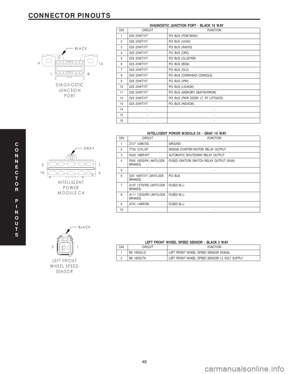
DIAGNOSTIC JUNCTION PORT - BLACK 16 WAYCAV CIRCUIT FUNCTION
1 D25 20WT/VT PCI BUS (PCM/SKIM)
2 D25 20WT/VT PCI BUS (HVAC)
3 D25 20WT/VT PCI BUS (RADIO)
4 D25 20WT/VT PCI BUS (ORC)
5 D25 20WT/VT PCI BUS (CLUSTER)
6 D25 20WT/VT PCI BUS (BCM)
7 D25 20WT/VT PCI BUS (DLC)
8 D25 20WT/VT PCI BUS (OVERHEAD CONSOLE)
9 D25 20WT/VT PCI BUS (IPM)
10 D25 20WT/VT PCI BUS (LSIACM)
11 D25 20WT/VT PCI BUS (MEMORY SEAT/MIRROR)
12 D25 20WT/VT PCI BUS (PWR DOOR/ LT, RT LIFTGATE)
13 D25 20WT/VT PCI BUS (RSIACM)
14 - -
15 - -
16 - -
INTELLIGENT POWER MODULE C4 - GRAY 10 WAYCAV CIRCUIT FUNCTION
1 Z127 12BK/DG GROUND
2 T750 12YL/GY ENGINE STARTER MOTOR RELAY OUTPUT
3 K342 16BR/WT AUTOMATIC SHUTDOWN RELAY OUTPUT
4 F500 18DG/PK (ANTILOCK
BRAKES)FUSED IGNITION SWITCH RELAY OUTPUT (RUN)
5- -
6 D25 16WT/VT (ANTILOCK
BRAKES)PCI BUS
7 A107 12TN/RD (ANTILOCK
BRAKES)FUSED B(+)
8 A111 12DG/RD (ANTILOCK
BRAKES)FUSED B(+)
9 A701 14BR/RD FUSED B(+)
10 - -
LEFT FRONT WHEEL SPEED SENSOR - BLACK 2 WAYCAV CIRCUIT FUNCTION
1 B9 18DG/LG LEFT FRONT WHEEL SPEED SENSOR SIGNAL
2 B8 18DG/TN LEFT FRONT WHEEL SPEED SENSOR 12 VOLT SUPPLY
C
O
N
N
E
C
T
O
R
P
I
N
O
U
T
S
48
CONNECTOR PINOUTS
Page 1215 of 4284
TABLE OF CONTENTS - Continued
P0100-MASS AIR FLOW SENSOR SUPPLY VOLTAGE TOO HIGH OR LOW......13
P0105-BAROMETRIC PRESSURE CIRCUIT SIGNAL VOLTAGE TOO HIGH.......20
P0105-BAROMETRIC PRESSURE CIRCUIT SIGNAL VOLTAGE TOO LOW........20
P0606-ECM ERROR GATE ARRAY - COMMUNICATION.......................20
P0606-ECM ERROR GATE ARRAY - COMMUNICATION NOT VERIFIED..........20
P0606-ECM ERROR GATE ARRAY - QUANTITY STOP........................20
P0606-ECM ERROR RECOVERY HAS OCCURRED..........................20
P0606-ECM ERROR REDUNDANT OVERRUN MONITORING..................20
P1206-CALCULATED INJECTOR VOLTAGE TOO HIGH........................20
P1206-CALCULATED INJECTOR VOLTAGE TOO LOW........................20
P1601-CAPACITOR VOLTAGE 1 VOLTAGE TOO HIGH........................20
P1601-CAPACITOR VOLTAGE 1 VOLTAGE TOO LOW.........................20
P1606-AFTER RUN SHUT OFF ERROR-INJECTION POWERSTAGE............20
P1606-AFTER RUN SHUT OFF ERROR-ZERO QUANTITY.....................20
P1610-VOLTAGE REGULATOR SIGNAL VOLTAGE TOO HIGH..................20
P1610-VOLTAGE REGULATOR SIGNAL VOLTAGE TOO LOW..................20
P1680-EEPROM PLAUSIBILITY CHECKSUM ERROR.........................20
P1680-EEPROM PLAUSIBILITY CODE WORD INCORRECT OR MISSING........20
P1680-EEPROM PLAUSIBILITY COMMUNICATION ERROR....................20
P1680-EEPROM PLAUSIBILITY VARIATION NUMBER ERROR.................20
P1680-EEPROM PLAUSIBILITY VIN CHECKSUM ERROR.....................20
P1680-EEPROM PLAUSIBILITY WRITE ERROR..............................20
P1696-EEPROM MEMORY WRITE DENIED.................................20
P0110-INTAKE AIR TEMP SENSOR CIRCUIT SIGNAL VOLTAGE TOO HIGH......24
P0110-INTAKE AIR TEMP SENSOR CIRCUIT SIGNAL VOLTAGE TOO LOW.......27
P0115-ENGINE COOLANT TEMP SENSOR CIRCUIT SIGNAL
VOLTAGE TOO HIGH....................................................29
P0115-ENGINE COOLANT TEMP SENSOR CIRCUIT SIGNAL
VOLTAGETOO LOW ....................................................32
P0190-FUEL PRESS SENSOR CIRCUIT MALF SIGNAL VOLTAGE TOO HIGH.....34
P0190-FUEL PRESS SENSOR CIRCUIT MALF SIGNAL VOLTAGE TOO LOW.....38
P0190-FUEL PRESS SENSOR CIRCUIT MALF SUPPLY VOLTAGE
TOO HIGH OR LOW.....................................................40
P0195-OIL TEMP SENSOR CIRCUIT MALF SIGNAL VOLTAGE TOO HIGH........41
P0195-OIL TEMP SENSOR CIRCUIT MALF SIGNAL VOLTAGE TOO LOW........44
P0201-CYLINDER 1-INJECTOR CIRCUIT CURRENT DECREASE...............46
P0201-CYLINDER 1-INJECTOR CIRCUIT LOAD DROP........................46
P0201-CYLINDER 1-INJECTOR CIRCUIT OVERCURRENT HIGH SIDE...........46
P0201-CYLINDER 1-INJECTOR CIRCUIT OVERCURRENT LOW SIDE...........46
P0202-CYLINDER 2-INJECTOR CIRCUIT CURRENT DECREASE...............50
P0202-CYLINDER 2-INJECTOR CIRCUIT LOAD DROP........................50
P0202-CYLINDER 2-INJECTOR CIRCUIT OVERCURRENT HIGH SIDE...........50
P0202-CYLINDER 2-INJECTOR CIRCUIT OVERCURRENT LOW SIDE...........50
P0203-CYLINDER 3-INJECTOR CIRCUIT CURRENT DECREASE...............54
P0203-CYLINDER 3-INJECTOR CIRCUIT LOAD DROP........................54
P0203-CYLINDER 3-INJECTOR CIRCUIT OVERCURRENT HIGH SIDE...........54
P0203-CYLINDER 3-INJECTOR CIRCUIT OVERCURRENT LOW SIDE...........54
P0204-CYLINDER 4-INJECTOR CIRCUIT CURRENT DECREASE...............58
P0204-CYLINDER 4-INJECTOR CIRCUIT LOAD DROP........................58
P0204-CYLINDER 4-INJECTOR CIRCUIT OVERCURRENT HIGH SIDE...........58
P0204-CYLINDER 4-INJECTOR CIRCUIT OVERCURRENT LOW SIDE...........58
P0235-BOOST PRESSURE SENSOR PLAUSIBILITY..........................62
P0235-BOOST PRESSURE SENSOR SIGNAL VOLTAGE TOO HIGH.............64
ii
Page 1217 of 4284
TABLE OF CONTENTS - Continued
P0703-BRAKE SWITCH SIGNAL CKTS PLAUS W/REDUNDANT CONTACT
AFTER INITIALIZATION.................................................149
P0833-CLUTCH PEDAL PLAUSIBILITY....................................153
P1130-FUEL RAIL PRESSURE MALFUNCTION LEAKAGE DETECTED..........155
P1130-FUEL RAIL PRESSURE MALFUNCTION PRESSURE TOO HIGH-SHUT
OFF .................................................................155
P1130-FUEL RAIL PRESSURE MALFUNCTION PRESSURE TOO LOW.........155
P1130-FUEL RAIL PRESSURE MALFUNCTION SOLENOID OPEN.............155
P1131-FUEL PRESSURE SOLENOID OPEN CIRCUIT........................158
P1131-FUEL PRESSURE SOLENOID PLAUSIBILITY IN AFTER-RUN............158
P1131-FUEL PRESSURE SOLENOID SHORT CIRCUIT.......................158
P1511-BATTERY SENSE LINE 1 VOLTAGE TOO HIGH.......................162
P1511-BATTERY SENSE LINE 1 VOLTAGE TOO LOW.......................164
P1605-IGNITION SWITCH PLAUSIBILITY..................................166
P1685-SKIM SYSTEM INVALID KEY CODE RECEIVED.......................168
P1685-SKIM SYSTEM INVALID SECRET KEY IN EEPROM....................168
P1685-SKIM SYSTEM KEY COMMUNICATION TIMED OUT...................168
P1685-SKIM SYSTEM SKIM ERROR......................................168
P1685-SKIM SYSTEM WRITE ACCESS TO EEPROM FAILURE................168
P2120-ACC PEDAL POSITION SENSOR 1 CKT PLAUSIBILITY................170
P2120-ACC PEDAL POSITION SENSOR 1 CKT PLAUSIBILITY WITH BRAKE
SWITCH..............................................................170
P2120-ACC PEDAL POSITION SENSOR 1 CKT PLAUSIBILITY WITH
POTENTIOMETER.....................................................170
P2120-ACC PEDAL POSITION SENSOR 1 CKT SIGNAL VOLTAGE TOO HIGH . . .170
P2120-ACC PEDAL POSITION SENSOR 1 CKT SIGNAL VOLTAGE TOO LOW . . .170
P2120-ACC PEDAL POSITION SENSOR 1 CKT SUPPLY VOLTAGE TOO
HIGH OR LOW........................................................170
*CHECKING THE A/C CLUTCH OPERATION...............................179
*CHECKING THE ACCELERATOR PEDAL POSITION SENSOR CALIBRATION . . .181
*CHECKING THE BOOST PRESSURE SENSOR CALIBRATION................182
*CHECKING THE ECM POWER AND GROUND CIRCUITS....................183
*CHECKING THE EGR SYSTEM..........................................185
*CHECKING THE ELECTRIC RADIATOR FAN OPERATION...................186
*CHECKING THE ENGINE COOLANT TEMPERATURE SENSOR CALIBRATION . .193
*CHECKING THE ENGINE MECHANICAL SYSTEMS.........................194
*CHECKING THE GLOW PLUG OPERATION...............................195
*CHECKING THE LIFT PUMP MOTOR OPERATION.........................197
*CHECKING THE MAF SENSOR CALIBRATION.............................200
*CHECKING THE SPEED CONTROL OPERATION...........................201
*CHECKING THE VEHICLE SPEED SIGNAL................................204
*ENGINE CRANKS BUT WILL NOT START.................................207
*ENGINE WILL NOT CRANK.............................................210
VEHICLE THEFT/SECURITY
ANTENNA FAILURE....................................................214
COP FAILURE.........................................................214
EEPROM FAILURE.....................................................214
INTERNAL FAULT......................................................214
RAM FAILURE.........................................................214
SERIAL LINK INTERNAL FAULT..........................................214
STACK OVERFLOW FAILURE............................................214
PCM STATUS FAILURE.................................................216
iv