2001 CHRYSLER VOYAGER transmission oil
[x] Cancel search: transmission oilPage 4121 of 4284
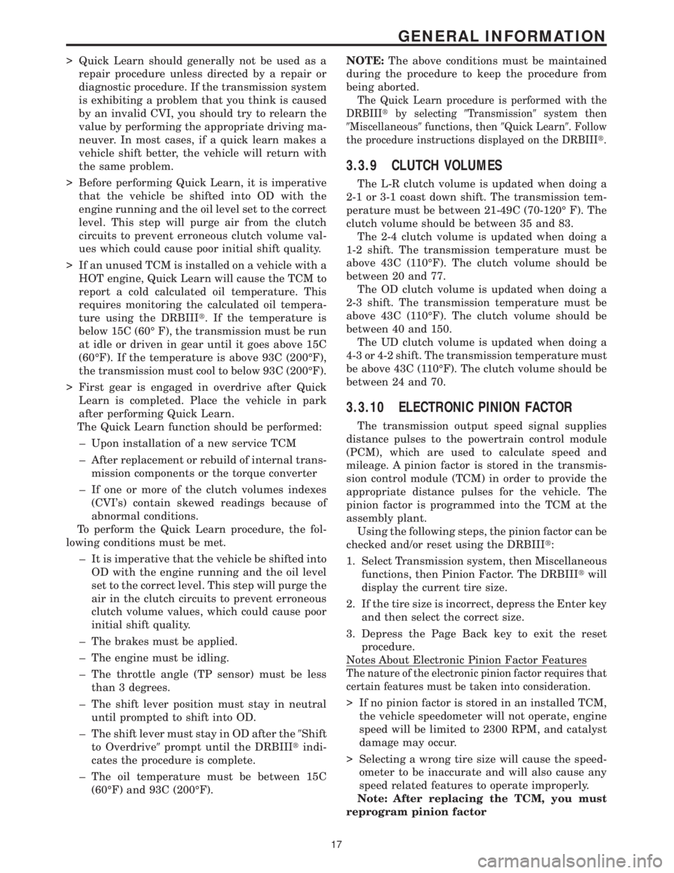
> Quick Learn should generally not be used as a
repair procedure unless directed by a repair or
diagnostic procedure. If the transmission system
is exhibiting a problem that you think is caused
by an invalid CVI, you should try to relearn the
value by performing the appropriate driving ma-
neuver. In most cases, if a quick learn makes a
vehicle shift better, the vehicle will return with
the same problem.
> Before performing Quick Learn, it is imperative
that the vehicle be shifted into OD with the
engine running and the oil level set to the correct
level. This step will purge air from the clutch
circuits to prevent erroneous clutch volume val-
ues which could cause poor initial shift quality.
> If an unused TCM is installed on a vehicle with a
HOT engine, Quick Learn will cause the TCM to
report a cold calculated oil temperature. This
requires monitoring the calculated oil tempera-
ture using the DRBIIIt. If the temperature is
below 15C (60É F), the transmission must be run
at idle or driven in gear until it goes above 15C
(60ÉF). If the temperature is above 93C (200ÉF),
the transmission must cool to below 93C (200ÉF).
> First gear is engaged in overdrive after Quick
Learn is completed. Place the vehicle in park
after performing Quick Learn.
The Quick Learn function should be performed:
± Upon installation of a new service TCM
± After replacement or rebuild of internal trans-
mission components or the torque converter
± If one or more of the clutch volumes indexes
(CVI's) contain skewed readings because of
abnormal conditions.
To perform the Quick Learn procedure, the fol-
lowing conditions must be met.
± It is imperative that the vehicle be shifted into
OD with the engine running and the oil level
set to the correct level. This step will purge the
air in the clutch circuits to prevent erroneous
clutch volume values, which could cause poor
initial shift quality.
± The brakes must be applied.
± The engine must be idling.
± The throttle angle (TP sensor) must be less
than 3 degrees.
± The shift lever position must stay in neutral
until prompted to shift into OD.
± The shift lever must stay in OD after the9Shift
to Overdrive9prompt until the DRBIIItindi-
cates the procedure is complete.
± The oil temperature must be between 15C
(60ÉF) and 93C (200ÉF).NOTE:The above conditions must be maintained
during the procedure to keep the procedure from
being aborted.
The Quick Learn procedure is performed with the
DRBIIItby selecting9Transmission9system then
9Miscellaneous9functions, then9Quick Learn9. Follow
the procedure instructions displayed on the DRBIIIt.
3.3.9 CLUTCH VOLUMES
The L-R clutch volume is updated when doing a
2-1 or 3-1 coast down shift. The transmission tem-
perature must be between 21-49C (70-120É F). The
clutch volume should be between 35 and 83.
The 2-4 clutch volume is updated when doing a
1-2 shift. The transmission temperature must be
above 43C (110ÉF). The clutch volume should be
between 20 and 77.
The OD clutch volume is updated when doing a
2-3 shift. The transmission temperature must be
above 43C (110ÉF). The clutch volume should be
between 40 and 150.
The UD clutch volume is updated when doing a
4-3 or 4-2 shift. The transmission temperature must
be above 43C (110ÉF). The clutch volume should be
between 24 and 70.
3.3.10 ELECTRONIC PINION FACTOR
The transmission output speed signal supplies
distance pulses to the powertrain control module
(PCM), which are used to calculate speed and
mileage. A pinion factor is stored in the transmis-
sion control module (TCM) in order to provide the
appropriate distance pulses for the vehicle. The
pinion factor is programmed into the TCM at the
assembly plant.
Using the following steps, the pinion factor can be
checked and/or reset using the DRBIIIt:
1. Select Transmission system, then Miscellaneous
functions, then Pinion Factor. The DRBIIItwill
display the current tire size.
2. If the tire size is incorrect, depress the Enter key
and then select the correct size.
3. Depress the Page Back key to exit the reset
procedure.
Notes About Electronic Pinion Factor Features
The nature of the electronic pinion factor requires that
certain features must be taken into consideration.
> If no pinion factor is stored in an installed TCM,
the vehicle speedometer will not operate, engine
speed will be limited to 2300 RPM, and catalyst
damage may occur.
> Selecting a wrong tire size will cause the speed-
ometer to be inaccurate and will also cause any
speed related features to operate improperly.
Note: After replacing the TCM, you must
reprogram pinion factor
17
GENERAL INFORMATION
Page 4123 of 4284
information at the time of publication. The right is
reserved to make changes at any time without
notice.
4.2.1 TECHNICIAN SAFETY INFORMATION
WARNING: ENGINES PRODUCE CARBON
MONOXIDE THAT IS ODORLESS, CAUSES
SLOWER REACTION TIMES AND CAN LEAD
TO SERIOUS INJURY. WHEN THE ENGINE IS
OPERATING, KEEP SERVICE AREAS WELL
VENTILATED OR ATTACH THE VEHICLE
EXHAUST SYSTEM TO THE SHOP EXHAUST
REMOVAL SYSTEM.
Some operations in this manual require that
hydraulic tubes, hoses, and fittings, disconnected
for inspection or testing purposes. These systems,
when fully charged contains fluid at high pressure.
Before disconnecting any hydraulic tubes, hoses or
fittings, be sure that the system is fully depressur-
ized.
When servicing a vehicle, always wear eye pro-
tection and remove any metal jewelry such as
watchbands or bracelets that might make an inad-
vertent electrical contact.
When diagnosing a transmission system problem,
it is important to follow approved procedures where
applicable. Following these procedures is very im-
portant to the safety of individuals performing
diagnostic tests.
4.2.2 VEHICLE PREPARATION FOR
TESTING
Make sure the vehicle being tested has a fully
charged battery. If it does not, false diagnostic codes
or error messages may occur. It is extremely impor-
tant that accurate shift lever position data be avail-
able to the TCM. The accuracy of any diagnostic
trouble code found in memory is doubtful unless the
Shift Lever Test, performed on the DRBtScan Tool,
passes.
4.2.3 SERVICING SUB-ASSEMBLIES
Some components of the powertrain system are
intended to be serviced in assembly only. Attempt-
ing to remove or repair certain system subcompo-
nents may result in personal injury and/or im-
proper system operation. Only those components
with approved repair and installation procedures in
the service instructions should be serviced.
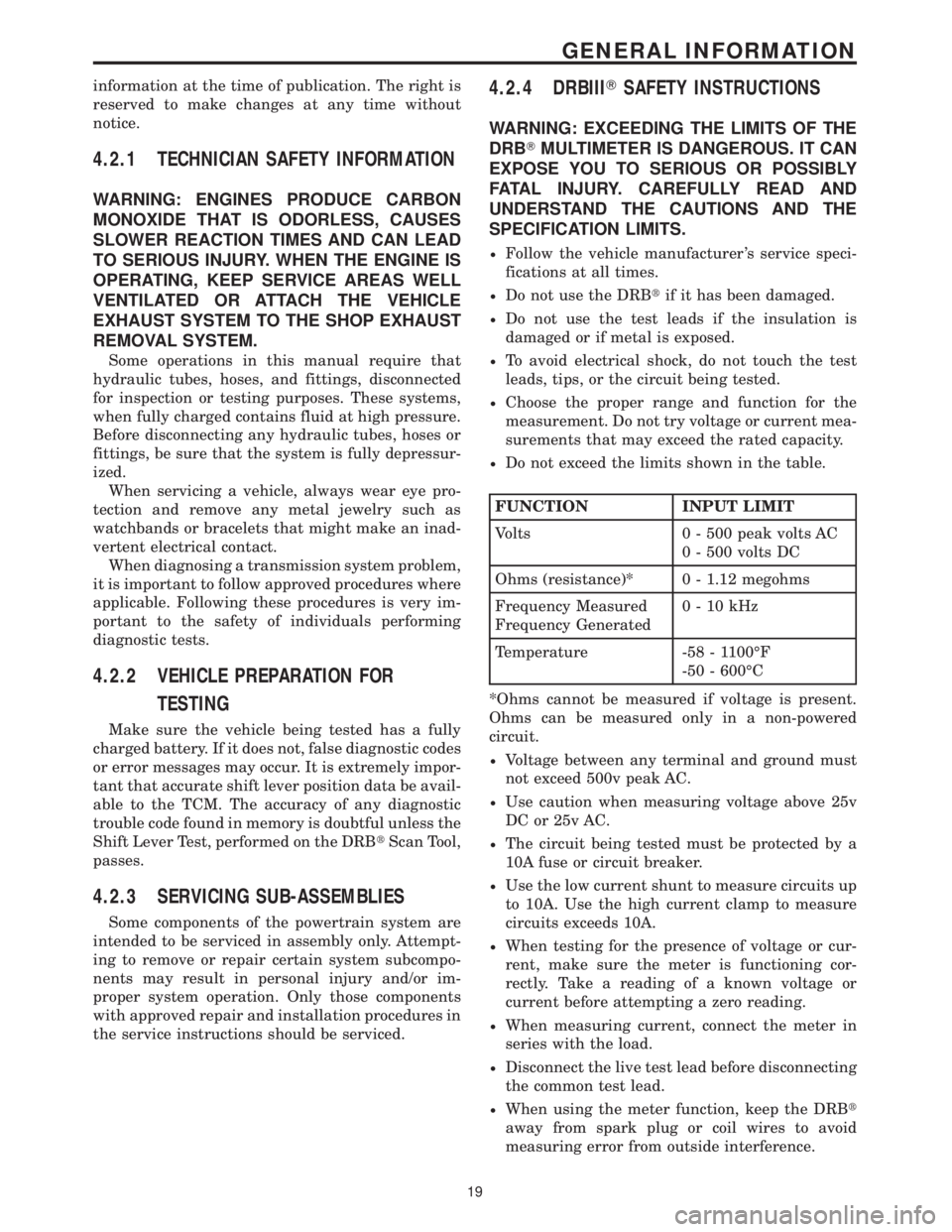
4.2.4 DRBIIITSAFETY INSTRUCTIONS
WARNING: EXCEEDING THE LIMITS OF THE
DRBTMULTIMETER IS DANGEROUS. IT CAN
EXPOSE YOU TO SERIOUS OR POSSIBLY
FATAL INJURY. CAREFULLY READ AND
UNDERSTAND THE CAUTIONS AND THE
SPECIFICATION LIMITS.
²Follow the vehicle manufacturer 's service speci-
fications at all times.
²Do not use the DRBtif it has been damaged.
²Do not use the test leads if the insulation is
damaged or if metal is exposed.
²To avoid electrical shock, do not touch the test
leads, tips, or the circuit being tested.
²Choose the proper range and function for the
measurement. Do not try voltage or current mea-
surements that may exceed the rated capacity.
²Do not exceed the limits shown in the table.
FUNCTION INPUT LIMIT
Volts 0 - 500 peak volts AC
0 - 500 volts DC
Ohms (resistance)* 0 - 1.12 megohms
Frequency Measured
Frequency Generated0-10kHz
Temperature -58 - 1100ÉF
-50 - 600ÉC
*Ohms cannot be measured if voltage is present.
Ohms can be measured only in a non-powered
circuit.
²Voltage between any terminal and ground must
not exceed 500v peak AC.
²Use caution when measuring voltage above 25v
DC or 25v AC.
²The circuit being tested must be protected by a
10A fuse or circuit breaker.
²Use the low current shunt to measure circuits up
to 10A. Use the high current clamp to measure
circuits exceeds 10A.
²When testing for the presence of voltage or cur-
rent, make sure the meter is functioning cor-
rectly. Take a reading of a known voltage or
current before attempting a zero reading.
²When measuring current, connect the meter in
series with the load.
²Disconnect the live test lead before disconnecting
the common test lead.
²When using the meter function, keep the DRBt
away from spark plug or coil wires to avoid
measuring error from outside interference.
19
GENERAL INFORMATION
Page 4156 of 4284
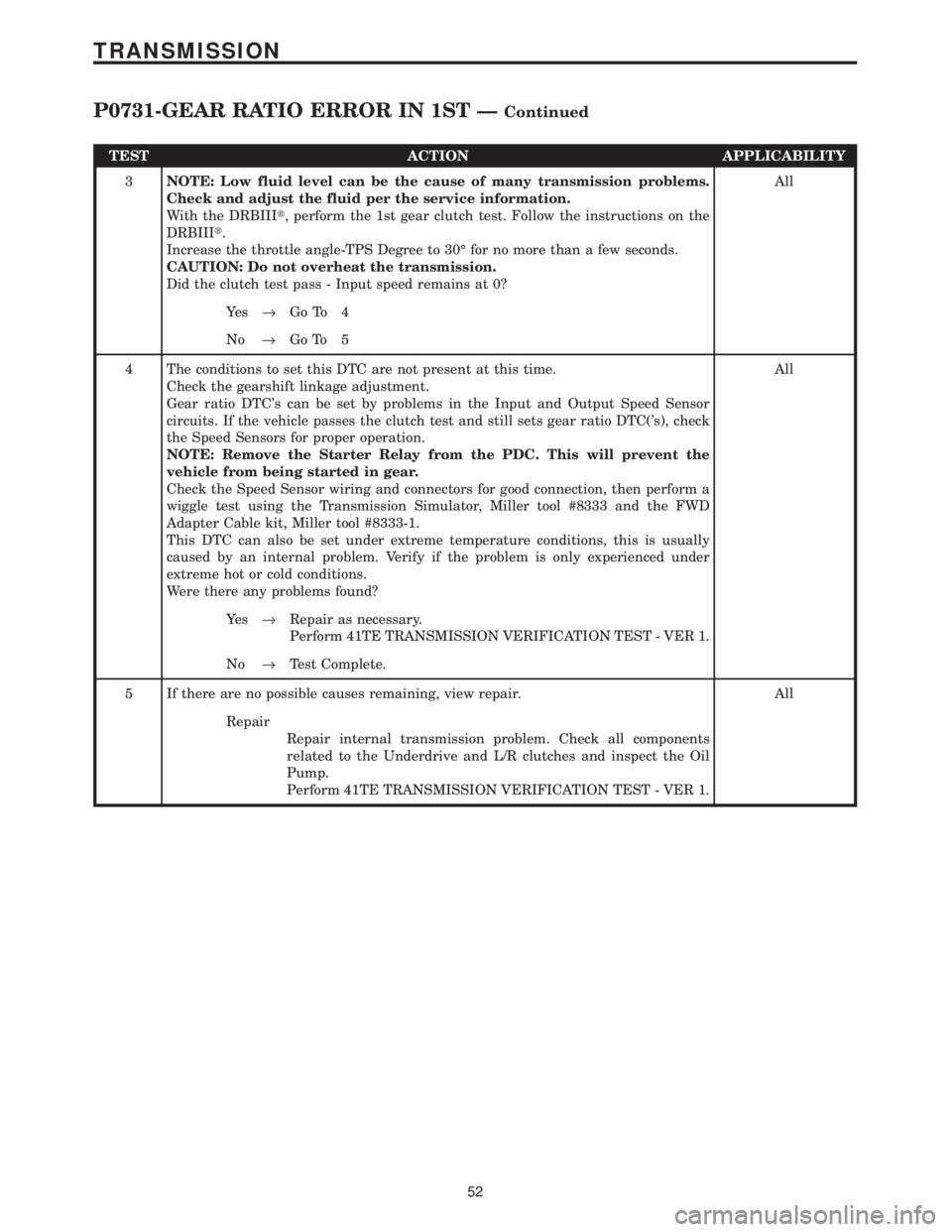
TEST ACTION APPLICABILITY
3NOTE: Low fluid level can be the cause of many transmission problems.
Check and adjust the fluid per the service information.
With the DRBIIIt, perform the 1st gear clutch test. Follow the instructions on the
DRBIIIt.
Increase the throttle angle-TPS Degree to 30É for no more than a few seconds.
CAUTION: Do not overheat the transmission.
Did the clutch test pass - Input speed remains at 0?All
Ye s®Go To 4
No®Go To 5
4 The conditions to set this DTC are not present at this time.
Check the gearshift linkage adjustment.
Gear ratio DTC's can be set by problems in the Input and Output Speed Sensor
circuits. If the vehicle passes the clutch test and still sets gear ratio DTC('s), check
the Speed Sensors for proper operation.
NOTE: Remove the Starter Relay from the PDC. This will prevent the
vehicle from being started in gear.
Check the Speed Sensor wiring and connectors for good connection, then perform a
wiggle test using the Transmission Simulator, Miller tool #8333 and the FWD
Adapter Cable kit, Miller tool #8333-1.
This DTC can also be set under extreme temperature conditions, this is usually
caused by an internal problem. Verify if the problem is only experienced under
extreme hot or cold conditions.
Were there any problems found?All
Ye s®Repair as necessary.
Perform 41TE TRANSMISSION VERIFICATION TEST - VER 1.
No®Test Complete.
5 If there are no possible causes remaining, view repair. All
Repair
Repair internal transmission problem. Check all components
related to the Underdrive and L/R clutches and inspect the Oil
Pump.
Perform 41TE TRANSMISSION VERIFICATION TEST - VER 1.
52
TRANSMISSION
P0731-GEAR RATIO ERROR IN 1ST ÐContinued
Page 4187 of 4284
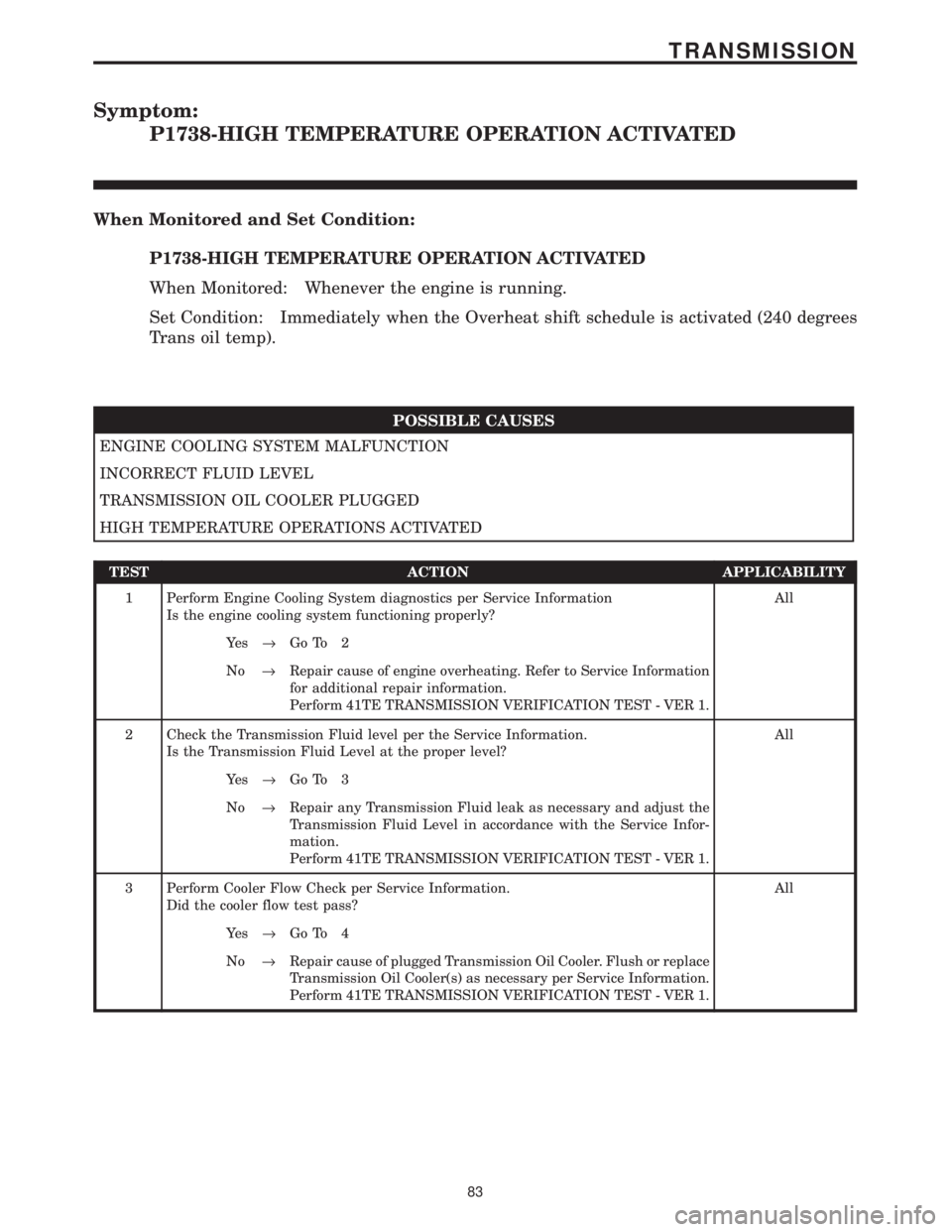
Symptom:
P1738-HIGH TEMPERATURE OPERATION ACTIVATED
When Monitored and Set Condition:
P1738-HIGH TEMPERATURE OPERATION ACTIVATED
When Monitored: Whenever the engine is running.
Set Condition: Immediately when the Overheat shift schedule is activated (240 degrees
Trans oil temp).
POSSIBLE CAUSES
ENGINE COOLING SYSTEM MALFUNCTION
INCORRECT FLUID LEVEL
TRANSMISSION OIL COOLER PLUGGED
HIGH TEMPERATURE OPERATIONS ACTIVATED
TEST ACTION APPLICABILITY
1 Perform Engine Cooling System diagnostics per Service Information
Is the engine cooling system functioning properly?All
Ye s®Go To 2
No®Repair cause of engine overheating. Refer to Service Information
for additional repair information.
Perform 41TE TRANSMISSION VERIFICATION TEST - VER 1.
2 Check the Transmission Fluid level per the Service Information.
Is the Transmission Fluid Level at the proper level?All
Ye s®Go To 3
No®Repair any Transmission Fluid leak as necessary and adjust the
Transmission Fluid Level in accordance with the Service Infor-
mation.
Perform 41TE TRANSMISSION VERIFICATION TEST - VER 1.
3 Perform Cooler Flow Check per Service Information.
Did the cooler flow test pass?All
Ye s®Go To 4
No®Repair cause of plugged Transmission Oil Cooler. Flush or replace
Transmission Oil Cooler(s) as necessary per Service Information.
Perform 41TE TRANSMISSION VERIFICATION TEST - VER 1.
83
TRANSMISSION
Page 4188 of 4284

TEST ACTION APPLICABILITY
4 This DTC is an informational DTC designed to aid the Technician in diagnosing shift
quality complaints.
This DTC indicates that the Transmission has been operating in the9Overheat9shift
schedule which may generate a customer complaint.
The customer driving patterns may indicate the need for an additional Transmission
Oil Cooler.
Were any problems found?All
Ye s®Repair cause of transmission overheating or if indicated install an
additional Transmission Oil Cooler.
Perform 41TE TRANSMISSION VERIFICATION TEST - VER 1.
No®Test Complete.
84
TRANSMISSION
P1738-HIGH TEMPERATURE OPERATION ACTIVATED ÐContinued
Page 4228 of 4284
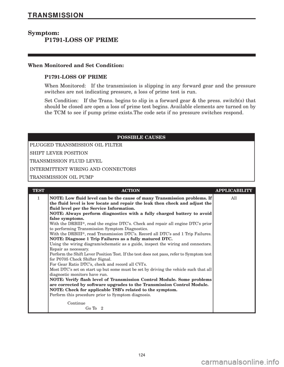
Symptom:
P1791-LOSS OF PRIME
When Monitored and Set Condition:
P1791-LOSS OF PRIME
When Monitored: If the transmission is slipping in any forward gear and the pressure
switches are not indicating pressure, a loss of prime test is run.
Set Condition: If the Trans. begins to slip in a forward gear & the press. switch(s) that
should be closed are open a loss of prime test begins. Available elements are turned on by
the TCM to see if pump prime exists.The code sets if no pressure switches respond.
POSSIBLE CAUSES
PLUGGED TRANSMISSION OIL FILTER
SHIFT LEVER POSITION
TRANSMISSION FLUID LEVEL
INTERMITTENT WIRING AND CONNECTORS
TRANSMISSION OIL PUMP
TEST ACTION APPLICABILITY
1NOTE: Low fluid level can be the cause of many Transmission problems. If
the fluid level is low locate and repair the leak then check and adjust the
fluid level per the Service Information.
NOTE: Always perform diagnostics with a fully charged battery to avoid
false symptoms.
With the DRBIIIt, read the engine DTC's. Check and repair all engine DTC's prior
to performing Transmission Symptom Diagnostics.
With the DRBIIIt, read Transmission DTC's. Record all DTC's and 1 Trip Failures.
NOTE: Diagnose 1 Trip Failures as a fully matured DTC.
Using the wiring diagram/schematic as a guide, inspect the wiring and connectors.
Repair as necessary.
Perform the Shift Lever Position Test. If the test does not pass, refer to Symptom test
for P0705 Check Shifter Signal.
For Gear Ratio DTC's, check and record all CVI's.
Most DTC's set on start up but some must be set by driving the vehicle such that all
diagnostic monitors have run.
NOTE: Verify flash level of Transmission Control Module. Some problems
are corrected by software upgrades to the Transmission Control Module.
NOTE: Check for applicable TSB's related to the symptom.
Perform this procedure prior to Symptom diagnosis.All
Continue
Go To 2
124
TRANSMISSION
Page 4229 of 4284
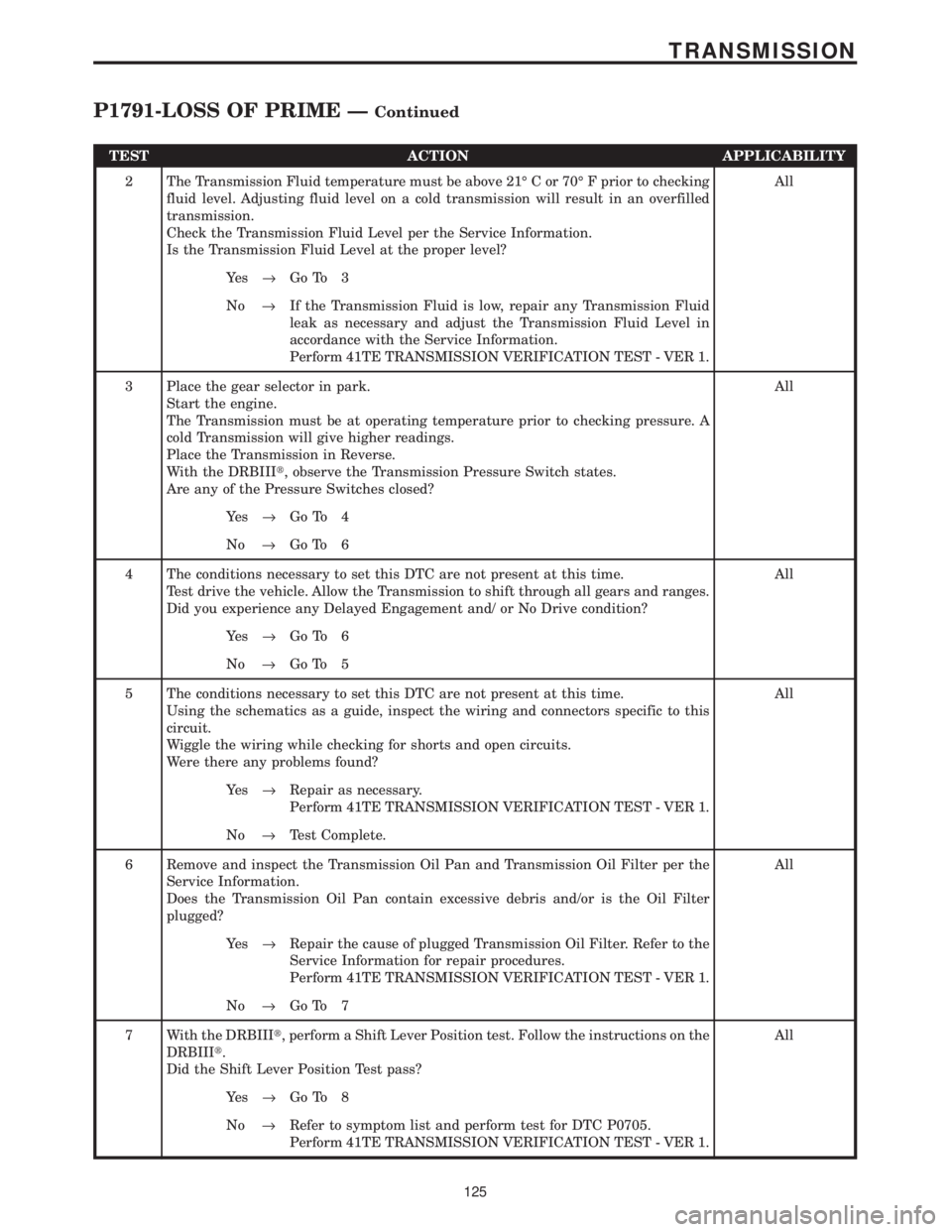
TEST ACTION APPLICABILITY
2 The Transmission Fluid temperature must be above 21É C or 70É F prior to checking
fluid level. Adjusting fluid level on a cold transmission will result in an overfilled
transmission.
Check the Transmission Fluid Level per the Service Information.
Is the Transmission Fluid Level at the proper level?All
Ye s®Go To 3
No®If the Transmission Fluid is low, repair any Transmission Fluid
leak as necessary and adjust the Transmission Fluid Level in
accordance with the Service Information.
Perform 41TE TRANSMISSION VERIFICATION TEST - VER 1.
3 Place the gear selector in park.
Start the engine.
The Transmission must be at operating temperature prior to checking pressure. A
cold Transmission will give higher readings.
Place the Transmission in Reverse.
With the DRBIIIt, observe the Transmission Pressure Switch states.
Are any of the Pressure Switches closed?All
Ye s®Go To 4
No®Go To 6
4 The conditions necessary to set this DTC are not present at this time.
Test drive the vehicle. Allow the Transmission to shift through all gears and ranges.
Did you experience any Delayed Engagement and/ or No Drive condition?All
Ye s®Go To 6
No®Go To 5
5 The conditions necessary to set this DTC are not present at this time.
Using the schematics as a guide, inspect the wiring and connectors specific to this
circuit.
Wiggle the wiring while checking for shorts and open circuits.
Were there any problems found?All
Ye s®Repair as necessary.
Perform 41TE TRANSMISSION VERIFICATION TEST - VER 1.
No®Test Complete.
6 Remove and inspect the Transmission Oil Pan and Transmission Oil Filter per the
Service Information.
Does the Transmission Oil Pan contain excessive debris and/or is the Oil Filter
plugged?All
Ye s®Repair the cause of plugged Transmission Oil Filter. Refer to the
Service Information for repair procedures.
Perform 41TE TRANSMISSION VERIFICATION TEST - VER 1.
No®Go To 7
7 With the DRBIIIt, perform a Shift Lever Position test. Follow the instructions on the
DRBIIIt.
Did the Shift Lever Position Test pass?All
Ye s®Go To 8
No®Refer to symptom list and perform test for DTC P0705.
Perform 41TE TRANSMISSION VERIFICATION TEST - VER 1.
125
TRANSMISSION
P1791-LOSS OF PRIME ÐContinued
Page 4230 of 4284
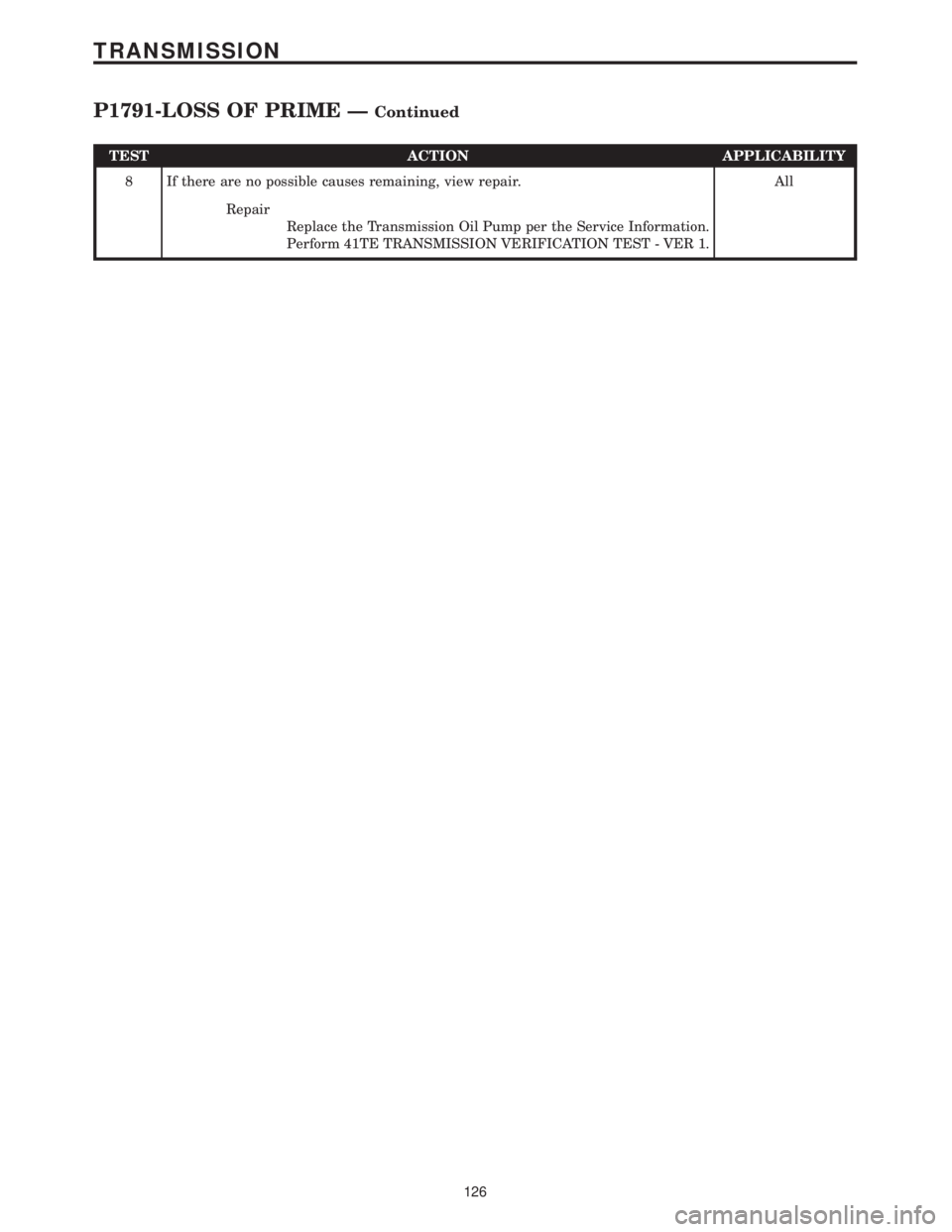
TEST ACTION APPLICABILITY
8 If there are no possible causes remaining, view repair. All
Repair
Replace the Transmission Oil Pump per the Service Information.
Perform 41TE TRANSMISSION VERIFICATION TEST - VER 1.
126
TRANSMISSION
P1791-LOSS OF PRIME ÐContinued