2001 CHRYSLER VOYAGER engine
[x] Cancel search: enginePage 4051 of 4284
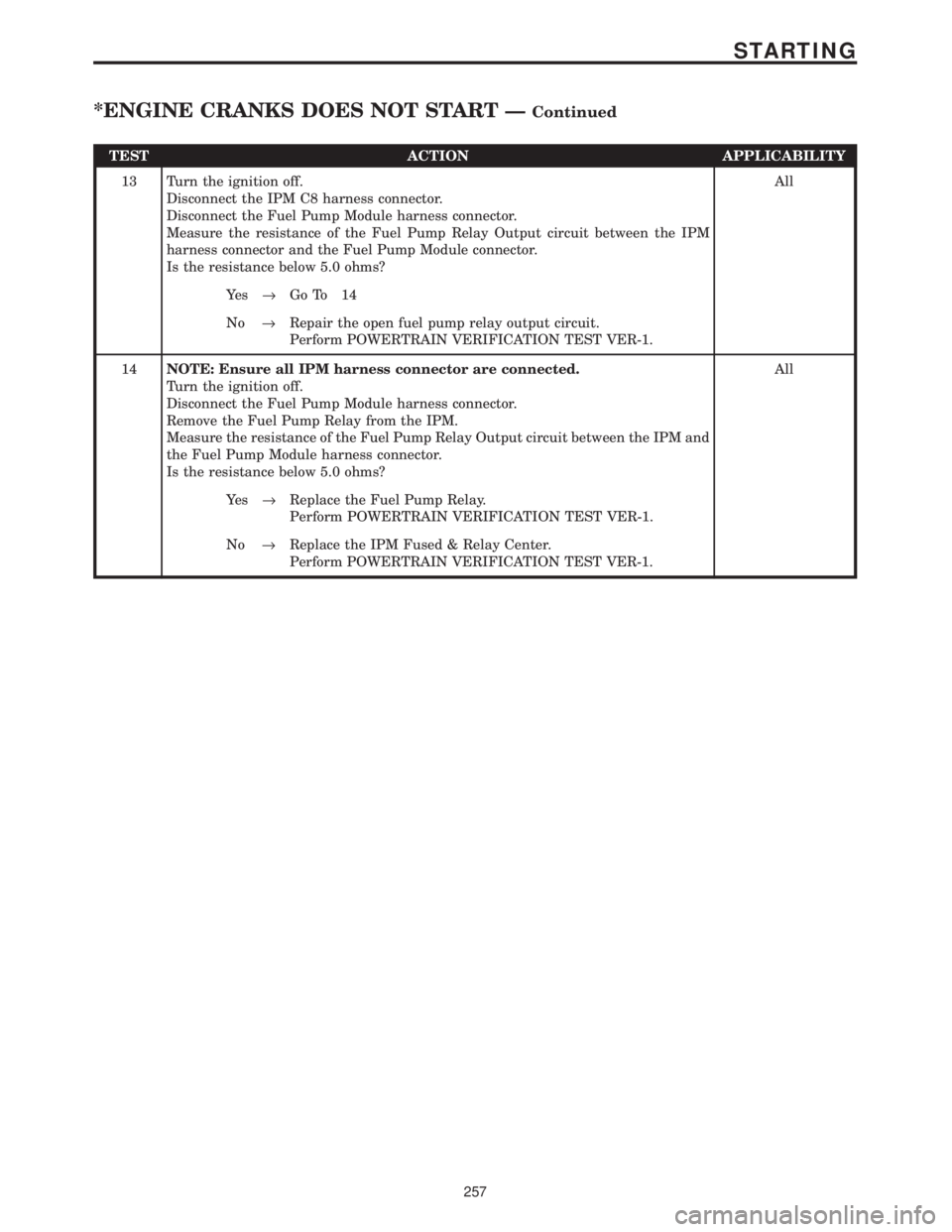
TEST ACTION APPLICABILITY
13 Turn the ignition off.
Disconnect the IPM C8 harness connector.
Disconnect the Fuel Pump Module harness connector.
Measure the resistance of the Fuel Pump Relay Output circuit between the IPM
harness connector and the Fuel Pump Module connector.
Is the resistance below 5.0 ohms?All
Ye s®Go To 14
No®Repair the open fuel pump relay output circuit.
Perform POWERTRAIN VERIFICATION TEST VER-1.
14NOTE: Ensure all IPM harness connector are connected.
Turn the ignition off.
Disconnect the Fuel Pump Module harness connector.
Remove the Fuel Pump Relay from the IPM.
Measure the resistance of the Fuel Pump Relay Output circuit between the IPM and
the Fuel Pump Module harness connector.
Is the resistance below 5.0 ohms?All
Ye s®Replace the Fuel Pump Relay.
Perform POWERTRAIN VERIFICATION TEST VER-1.
No®Replace the IPM Fused & Relay Center.
Perform POWERTRAIN VERIFICATION TEST VER-1.
257
STARTING
*ENGINE CRANKS DOES NOT START ÐContinued
Page 4052 of 4284
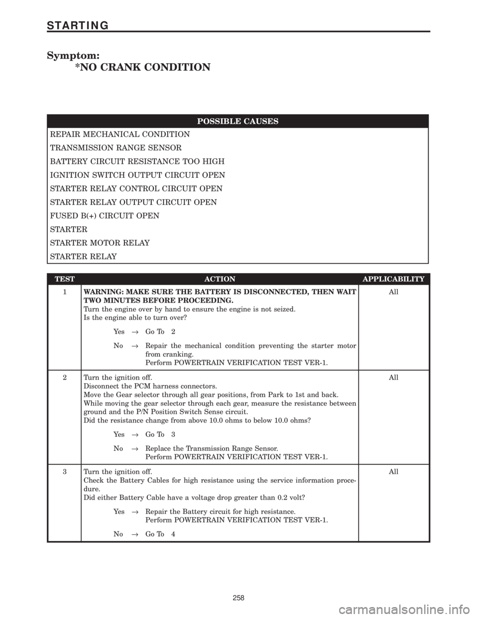
Symptom:
*NO CRANK CONDITION
POSSIBLE CAUSES
REPAIR MECHANICAL CONDITION
TRANSMISSION RANGE SENSOR
BATTERY CIRCUIT RESISTANCE TOO HIGH
IGNITION SWITCH OUTPUT CIRCUIT OPEN
STARTER RELAY CONTROL CIRCUIT OPEN
STARTER RELAY OUTPUT CIRCUIT OPEN
FUSED B(+) CIRCUIT OPEN
STARTER
STARTER MOTOR RELAY
STARTER RELAY
TEST ACTION APPLICABILITY
1WARNING: MAKE SURE THE BATTERY IS DISCONNECTED, THEN WAIT
TWO MINUTES BEFORE PROCEEDING.
Turn the engine over by hand to ensure the engine is not seized.
Is the engine able to turn over?All
Ye s®Go To 2
No®Repair the mechanical condition preventing the starter motor
from cranking.
Perform POWERTRAIN VERIFICATION TEST VER-1.
2 Turn the ignition off.
Disconnect the PCM harness connectors.
Move the Gear selector through all gear positions, from Park to 1st and back.
While moving the gear selector through each gear, measure the resistance between
ground and the P/N Position Switch Sense circuit.
Did the resistance change from above 10.0 ohms to below 10.0 ohms?All
Ye s®Go To 3
No®Replace the Transmission Range Sensor.
Perform POWERTRAIN VERIFICATION TEST VER-1.
3 Turn the ignition off.
Check the Battery Cables for high resistance using the service information proce-
dure.
Did either Battery Cable have a voltage drop greater than 0.2 volt?All
Ye s®Repair the Battery circuit for high resistance.
Perform POWERTRAIN VERIFICATION TEST VER-1.
No®Go To 4
258
STARTING
Page 4053 of 4284

TEST ACTION APPLICABILITY
4 Turn ignition off.
Remove the Starter Relay from PDC.
WARNING: The Parking Brake must be on and the Transmission must be in
park for a vehicle equipped with an automatic transmission.
Warning: The engine may be cranked in the next step. Keep away from
moving engine parts.
Briefly connect a jumper wire between Starter Relay B+ circuit and the Starter Relay
Output Circuits.
Did the Starter Motor crank the engine?All
Ye s®Go To 5
No®Go To 8
5 Turn the ignition off.
Remove the Starter Relay from the PDC.
Turn the ignition on.
Using a 12-volt test light, probe the Ignition Switch Output circuit in the Starter
Relay connector.
While observing 12-volt test light, hold ignition key in the start position.
Does the test light illuminate brightly?All
Ye s®Go To 6
No®Repair the Ignition Switch Output circuit for an open or high
resistance.
Perform POWERTRAIN VERIFICATION TEST VER-1.
6 Turn the ignition off.
Remove the Starter Relay from the PDC.
Disconnect the PCM harness connector.
Measure the Starter Relay Control circuit between the Relay terminal and the PCM
harness connector.
Is the resistance below 5.0 ohms?All
Ye s®Go To 7
No®Repair the Starter Relay Control circuit for an open.
Perform POWERTRAIN VERIFICATION TEST VER-1.
7 Turn the ignition off.
Install a substitute a Relay in the of the Starter Motor Relay.
Attempt to start the vehicle.
Does the engine crank over?All
Ye s®Replace the Starter Motor Relay.
Perform POWERTRAIN VERIFICATION TEST VER-1.
No®Replace and program the Powertrain Control Module in accor-
dance with the Service Information.
Perform POWERTRAIN VERIFICATION TEST VER-1.
259
STARTING
*NO CRANK CONDITION ÐContinued
Page 4057 of 4284
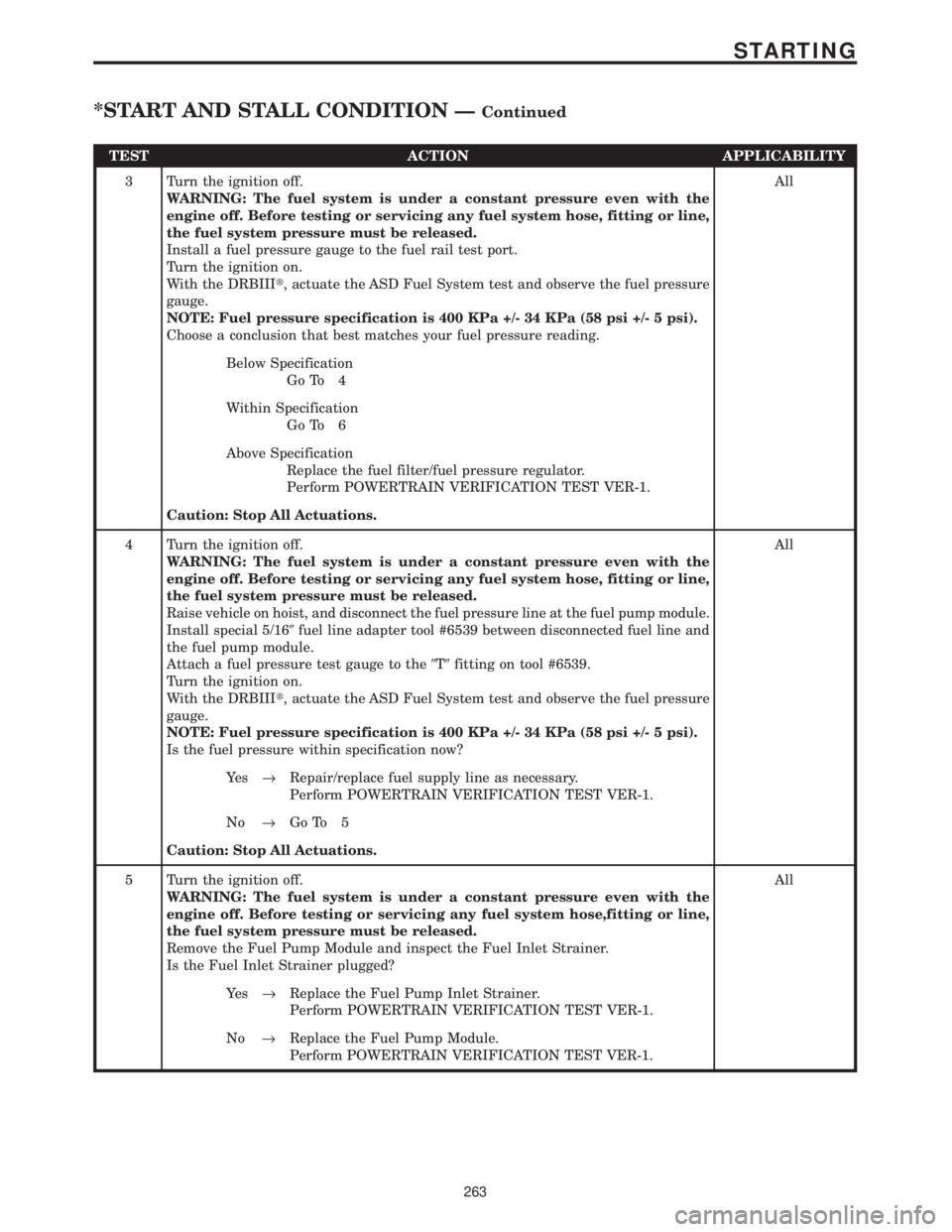
TEST ACTION APPLICABILITY
3 Turn the ignition off.
WARNING: The fuel system is under a constant pressure even with the
engine off. Before testing or servicing any fuel system hose, fitting or line,
the fuel system pressure must be released.
Install a fuel pressure gauge to the fuel rail test port.
Turn the ignition on.
With the DRBIIIt, actuate the ASD Fuel System test and observe the fuel pressure
gauge.
NOTE: Fuel pressure specification is 400 KPa +/- 34 KPa (58 psi +/- 5 psi).
Choose a conclusion that best matches your fuel pressure reading.All
Below Specification
Go To 4
Within Specification
Go To 6
Above Specification
Replace the fuel filter/fuel pressure regulator.
Perform POWERTRAIN VERIFICATION TEST VER-1.
Caution: Stop All Actuations.
4 Turn the ignition off.
WARNING: The fuel system is under a constant pressure even with the
engine off. Before testing or servicing any fuel system hose, fitting or line,
the fuel system pressure must be released.
Raise vehicle on hoist, and disconnect the fuel pressure line at the fuel pump module.
Install special 5/169fuel line adapter tool #6539 between disconnected fuel line and
the fuel pump module.
Attach a fuel pressure test gauge to the9T9fitting on tool #6539.
Turn the ignition on.
With the DRBIIIt, actuate the ASD Fuel System test and observe the fuel pressure
gauge.
NOTE: Fuel pressure specification is 400 KPa +/- 34 KPa (58 psi +/- 5 psi).
Is the fuel pressure within specification now?All
Ye s®Repair/replace fuel supply line as necessary.
Perform POWERTRAIN VERIFICATION TEST VER-1.
No®Go To 5
Caution: Stop All Actuations.
5 Turn the ignition off.
WARNING: The fuel system is under a constant pressure even with the
engine off. Before testing or servicing any fuel system hose,fitting or line,
the fuel system pressure must be released.
Remove the Fuel Pump Module and inspect the Fuel Inlet Strainer.
Is the Fuel Inlet Strainer plugged?All
Ye s®Replace the Fuel Pump Inlet Strainer.
Perform POWERTRAIN VERIFICATION TEST VER-1.
No®Replace the Fuel Pump Module.
Perform POWERTRAIN VERIFICATION TEST VER-1.
263
STARTING
*START AND STALL CONDITION ÐContinued
Page 4058 of 4284
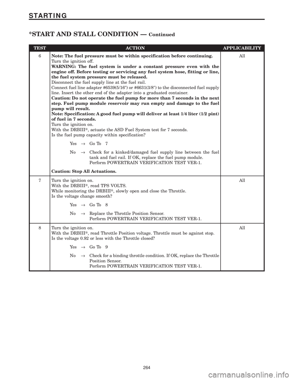
TEST ACTION APPLICABILITY
6Note: The fuel pressure must be within specification before continuing.
Turn the ignition off.
WARNING: The fuel system is under a constant pressure even with the
engine off. Before testing or servicing any fuel system hose, fitting or line,
the fuel system pressure must be released.
Disconnect the fuel supply line at the fuel rail.
Connect fuel line adapter #6539(5/169) or #6631(3/89) to the disconnected fuel supply
line. Insert the other end of the adapter into a graduated container.
Caution: Do not operate the fuel pump for more than 7 seconds in the next
step. Fuel pump module reservoir may run empty and damage to the fuel
pump will result.
Note: Specification: A good fuel pump will deliver at least 1/4 liter (1/2 pint)
of fuel in 7 seconds.
Turn the ignition on.
With the DRBIIIt, actuate the ASD Fuel System test for 7 seconds.
Is the fuel pump capacity within specification?All
Ye s®Go To 7
No®Check for a kinked/damaged fuel supply line between the fuel
tank and fuel rail. If OK, replace the fuel pump module.
Perform POWERTRAIN VERIFICATION TEST VER-1.
Caution: Stop All Actuations.
7 Turn the ignition on.
With the DRBIIIt, read TPS VOLTS.
While monitoring the DRBIIIt, slowly open and close the Throttle.
Is the voltage change smooth?All
Ye s®Go To 8
No®Replace the Throttle Position Sensor.
Perform POWERTRAIN VERIFICATION TEST VER-1.
8 Turn the ignition on.
With the DRBIIIt, read Throttle Position voltage. Throttle must be against stop.
Is the voltage 0.92 or less with the Throttle closed?All
Ye s®Go To 9
No®Check for a binding throttle condition. If OK, replace the Throttle
Position Sensor.
Perform POWERTRAIN VERIFICATION TEST VER-1.
264
STARTING
*START AND STALL CONDITION ÐContinued
Page 4059 of 4284
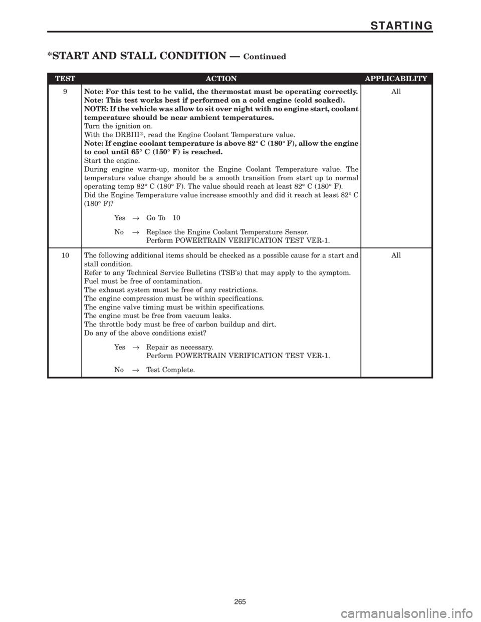
TEST ACTION APPLICABILITY
9Note: For this test to be valid, the thermostat must be operating correctly.
Note: This test works best if performed on a cold engine (cold soaked).
NOTE: If the vehicle was allow to sit over night with no engine start, coolant
temperature should be near ambient temperatures.
Turn the ignition on.
With the DRBIIIt, read the Engine Coolant Temperature value.
Note: If engine coolant temperature is above 82É C (180É F), allow the engine
to cool until 65É C (150É F) is reached.
Start the engine.
During engine warm-up, monitor the Engine Coolant Temperature value. The
temperature value change should be a smooth transition from start up to normal
operating temp 82É C (180É F). The value should reach at least 82É C (180É F).
Did the Engine Temperature value increase smoothly and did it reach at least 82É C
(180É F)?All
Ye s®Go To 10
No®Replace the Engine Coolant Temperature Sensor.
Perform POWERTRAIN VERIFICATION TEST VER-1.
10 The following additional items should be checked as a possible cause for a start and
stall condition.
Refer to any Technical Service Bulletins (TSB's) that may apply to the symptom.
Fuel must be free of contamination.
The exhaust system must be free of any restrictions.
The engine compression must be within specifications.
The engine valve timing must be within specifications.
The engine must be free from vacuum leaks.
The throttle body must be free of carbon buildup and dirt.
Do any of the above conditions exist?All
Ye s®Repair as necessary.
Perform POWERTRAIN VERIFICATION TEST VER-1.
No®Test Complete.
265
STARTING
*START AND STALL CONDITION ÐContinued
Page 4064 of 4284
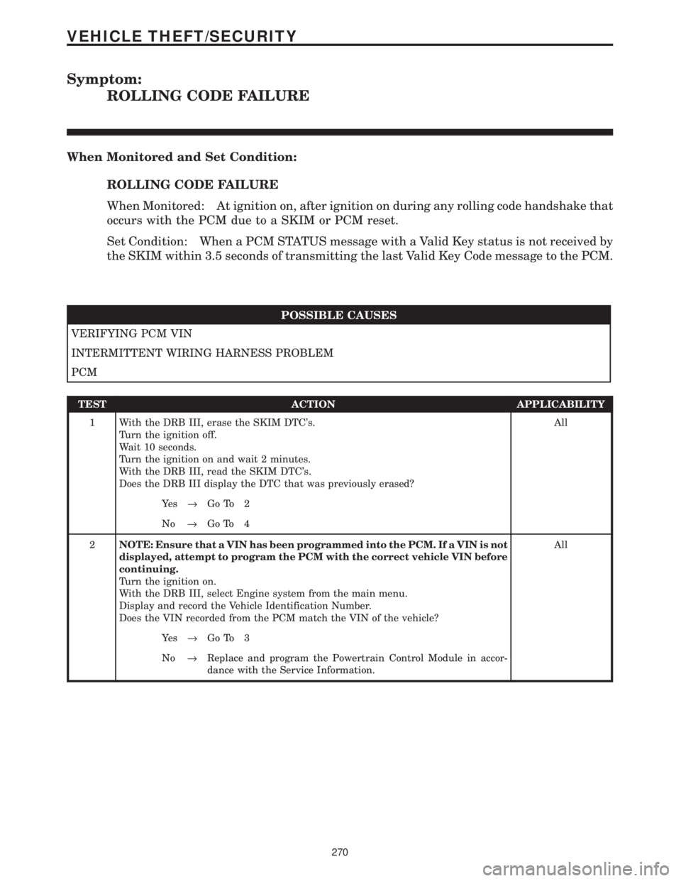
Symptom:
ROLLING CODE FAILURE
When Monitored and Set Condition:
ROLLING CODE FAILURE
When Monitored: At ignition on, after ignition on during any rolling code handshake that
occurs with the PCM due to a SKIM or PCM reset.
Set Condition: When a PCM STATUS message with a Valid Key status is not received by
the SKIM within 3.5 seconds of transmitting the last Valid Key Code message to the PCM.
POSSIBLE CAUSES
VERIFYING PCM VIN
INTERMITTENT WIRING HARNESS PROBLEM
PCM
TEST ACTION APPLICABILITY
1 With the DRB III, erase the SKIM DTC's.
Turn the ignition off.
Wait 10 seconds.
Turn the ignition on and wait 2 minutes.
With the DRB III, read the SKIM DTC's.
Does the DRB III display the DTC that was previously erased?All
Ye s®Go To 2
No®Go To 4
2NOTE: Ensure that a VIN has been programmed into the PCM. If a VIN is not
displayed, attempt to program the PCM with the correct vehicle VIN before
continuing.
Turn the ignition on.
With the DRB III, select Engine system from the main menu.
Display and record the Vehicle Identification Number.
Does the VIN recorded from the PCM match the VIN of the vehicle?All
Ye s®Go To 3
No®Replace and program the Powertrain Control Module in accor-
dance with the Service Information.
270
VEHICLE THEFT/SECURITY
Page 4069 of 4284
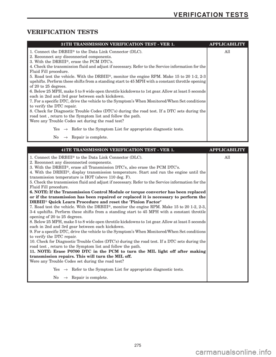
VERIFICATION TESTS
31TH TRANSMISSION VERIFICATION TEST - VER 1. APPLICABILITY
1. Connect the DRBIIItto the Data Link Connector (DLC).
2. Reconnect any disconnected components.
3. With the DRBIIIt, erase the PCM DTC's.
4. Check the transmission fluid and adjust if necessary. Refer to the Service information for the
Fluid Fill procedure.
5. Road test the vehicle. With the DRBIIIt, monitor the engine RPM. Make 15 to 20 1-2, 2-3
upshifts. Perform these shifts from a standing start to 45 MPH with a constant throttle opening
of 20 to 25 degrees.
6. Below 25 MPH, make 5 to 8 wide open throttle kickdowns to 1st gear. Allow at least 5 seconds
each in 2nd and 3rd gear between each kickdown.
7. For a specific DTC, drive the vehicle to the Symptom's When Monitored/When Set conditions
to verify the DTC repair.
8. Check for Diagnostic Trouble Codes (DTC's) during the road test. If a DTC sets during the
road test , return to the Symptom list and follow the path.
Were any Trouble Codes set during the road test?All
Ye s®Refer to the Symptom List for appropriate diagnostic tests.
No®Repair is complete.
41TE TRANSMISSION VERIFICATION TEST - VER 1. APPLICABILITY
1. Connect the DRBIIItto the Data Link Connector (DLC).
2. Reconnect any disconnected components.
3. With the DRBIIIt, erase all Transmission DTC's, also erase the PCM DTC's.
4. With the DRBIIIt, display transmission temperature. Start and run the engine until the
transmission temperature is HOT (above 110 deg. F).
5. Check the transmission fluid and adjust if necessary. Refer to the Service information for the
Fluid Fill procedure.
6. NOTE: If the Transmission Control Module or torque converter has been replaced
or if the transmission has been repaired or replaced it is necessary to perform the
DRBIIItQuick Learn Procedure and reset the(Pinion Factor(
7. Road test the vehicle. With the DRBIIIt, monitor the engine RPM. Make 15 to 20 1-2, 2-3,
3-4 upshifts. Perform these shifts from a standing start to 45 MPH with a constant throttle
opening of 20 to 25 degrees.
8. Below 25 MPH, make 5 to 8 wide open throttle kickdowns to 1st gear. Allow at least 5 seconds
each in 2nd and 3rd gear between each kickdown.
9. For a specific DTC, drive the vehicle to the Symptom's When Monitored/When Set conditions
to verify the DTC repair.
10. Check for Diagnostic Trouble Codes (DTC's) during the road test. If a DTC sets during the
road test , return to the Symptom list and follow the path.
11. NOTE: Erase P0700 DTC in the PCM to turn the MIL light off after making
transmission repairs. This will turn the MIL off.
Were any Trouble Codes set during the road test?All
Ye s®Refer to the Symptom List for appropriate diagnostic tests.
No®Repair is complete.
275
VERIFICATION TESTS